Note: Descriptions are shown in the official language in which they were submitted.
CA 02335432 2001-02-23
-1-
FOOTWEAR
The present invention relates to a footwear, and particularly
to a boot to be used with a runner such as a boot for an ice, inline, or
roller skate, cross country ski, snowboard, etc.
s This application is a divisional application of application
Serial No. 2,268,893 filed September 18, 1998.
The developments of skate boots in the last twenty years
have been in the direction of a more rigid boot partly because of the
advent of molded plastic shells for the construction of skate boots. Such
techniques have allowed a more rigid construction of the uppers,
presumably to increase performance, and to improve the protection of the
skater. However, there is little consideration for the anatomy or the
biomechanics of the foot. The foot is a very complex biomechanical
structure with scores of articulates bones, cartilage and muscles. When
the foot is encased in a conventional molded plastic shell, little of the
mechanical advantages of the complex leverage movements can be
transferred to the runner, i.e. blade inline rollers or cross country ski,
because of the rigidity of the shell and the instability of the foot within
the
slipper.
zo The rigid shell forming the upper, in conventional molded
skate boots, is uncomfortable. Various soft inner boots or slippers have
been designed for use with such rigid boots to be adapted and to be
formed to the foot of the wearer. However, the skate is not therefore
responsive to the thrust of the foot. Some of the force being transferred to
z5 the foot laterally, or torquewise, is loss due to the movement of the
slipper
relative to the shell.
It is an aim of the present invention to provide a boot which
is comfortable while providing stability for the foot, thereby providing a
high degree of performance.
CA 02335432 2001-02-23
-2-
It is a further aim of the present invention to provide a boot
which is designed respecting anatomy and biomechanical aspects of the
foot.
It is a further aim of the present invention to provide a boot
which has a relatively rigid upper and provided with selected flexible
portions to allow suitable flexion extension about the ankle.
It is a further aim of the present invention to provide a boot
which better blocks the foot and ankle in the boot to prevent power loss.
It is a further aim of the present invention to provide a rigid
~o toe box for a boot which respects the asymmetric anatomy of the
articulated structure of the foot.
It is a further aim of the present invention to provide a boot
upper having a lateral quarter and a medial quarter which are asymmetric
and mostly rigid.
15 It is a further aim of the present invention to provide a pair
of flexible compressible wall portions provided in the lateral and medial
quarters but aligned in a plane containing the general flexion and
extension movements of the foot in relation to the ankle.
It is an aim of the present invention to provide a boot
Zo suitable for gliding sports which provides an improvement in comfort,
adaptability, foot stability and performance.
In one aspect of the present invention there is provided a
toe box having a rigid one piece shell for a boot having a sole with a toe
portion, a heel portion, the toe box having a lower edge coincident with
z5 the sole in the toe portion and the rear edge thereof defines the extent of
the shell which is asymmetric and has a somewhat parabolic outline
between a portion coincident with the joint of the first metatarsal shaft and
the respective phalange, and another portion coincident with the joint of
the fifth metatarsal bone and the respective phalange.
3o In a further construction of the present invention the medial
quarter and the lateral quarter are each provided with a flexible
compressible area aligned in a common axis which extends in the medial
CA 02335432 2001-02-23
-3-
dorsal area and posterior lateral area in order to permit flexion and
extension of the foot about the axis of the ankle during the skating action.
Having thus generally described the nature of the invention,
reference will now be made to the accompanying drawings, showing by
s way of illustration, a preferred embodiment thereof, and in which:
Figure 1 is a perspective view of a boot in accordance with
the present invention;
Figure 2 is a side elevation taken from the medial side of
the boot;
Figure 3 is a front elevation thereof;
Figure 4 is a side elevation taken from the lateral side of the
boot;
Figure 5 is a rear elevation thereof;
Figure 6 is a side elevation taken from the medial side
15 showing the spatial arrangement of the pads and foot bed of the present
invention;
Figure 7 is a front elevation of the spatial arrangement
shown in Figure 6;
Figure 8 is a side elevation taken from the lateral side of the
zo spatial arrangement shown in Figures 6 and 7;
Figure 9 is a rear elevation thereof;
Figure 10a is a front elevation view of another embodiment
of the lateral malleolar pad;
Figures 10b, 10c, and 10d represent rear, front, and side
z5 views of the malleolar pad shown in Figures 10a in position on the foot
shown in dotted lines;
Figure 11 a is a front elevation of a medial malleolar pad of
the same embodiment as that shown in Figures 10a; and
Figures 11 b through 11 d represent rear, front, and side
3o views of the medial malleolar pad in position on a foot shown in dotted
lines.
CA 02335432 2001-02-23
-4-
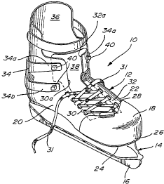
Referring now to Figs. 1 to 5 there is shown a skate 10
including a boot 12, a blade support 14, and blade 16. The blade
support 14 and the blade 16 are of conventional construction. It is also
understood that the boot 12 can be utilized with an inline roller skate
s support with similar advantages.
It is also contemplated that the boot 12 can be adapted for
use with other so called gliding sports such as cross country skiing,
specially when using equipment for the skating technique. The boot 12
could also be adapted for other gliding sports such as snow-boarding,
~o skiing, etc.
The boot 12 includes an upper formed with a rigid toe box
18, a lateral quarter 20 and a medial quarter 22. A sole 24 is also provided
to which the blade support is fixed.
The toe box 18 includes a lower edge 26 coincident with
15 the edge of the sole 24, the toe box 18 extends rearwardly on the medial
side and on the dorsal portion to cover the first metatarsal shaft and must
extend laterally rearwardly to cover the fifth metatarsal bone.
The rear edge 28 of the box 18 defines a somewhat
parabolic curve in the area of the vamp to coincide with the joints of the
zo second, third, and fourth metatarsal heads. The toe box 18 should be
one-piece molded, rigid plastic material with means provided for fastening
the tongue 38 as will be described.
The upper includes a lateral quarter 20 and a medial
quarter 22 which may be two asymmetric independent pieces joined
z5 together in the area of the Achilles tendon or may be a one piece molded
plastic shell.
The lateral quarter 20 includes an eyelet row 30 which is
aligned with the fourth metatarsal bone. The lateral quarter is fixed along
its edge to the sole 24 and forwardly along the rear edge 28 of the toe box
30 18. The upper portion of the forward edge 30a of the lateral quarter 20 is
offset from the alignment of the eyelet row 30 in order that it would be
symmetrical with the anterior portion of the ankle.
CA 02335432 2001-02-23
-5-
The medial quarter 22 as shown in Figs. 1, 2, and 3
includes an eyelet row 32 which is aligned with the second metatarsal
bone. The gap between the eyelet rows 30 and 32 is offset with respect to
the longitudinal axis of the boot as best seen in Fig. 3. The medial quarter
s 22 is joined at its lower edge to the sole 24 and at its forward edge to the
rear edge 28 of the toe box 18. The upper edge 32a of the medial quarter
22 is offset from the alignment of the eyelet row 32 and along with the
upper forward edge 30a of quarter 20 to form a gap which is in alignment
with the anterior portion of the ankle, that is with the longitudinal axis of
the boot. Thus, in appearance the lacing gap appears to be scewered
when seen from the front view as shown in Figs. 1 and 3.
A lacing band 34 having forwardly extending pairs of fingers
34a and 34b is loosely mounted to the rear of the boot with the fingers
extending forwardly and presenting lacing hooks 40. The lacing band 34 is
15 fixed at least at one point to the rear portion of the upper, at least in
the
area of the Achilles tendon. The fingers 34a and 34b on either side of the
boot 12 are not directly connected to their respective quarters 20 and 22.
Thus, when it is necessary to mount the boot the lacing 31 is first passed
through the pairs of eyelets 30 and 32 and then crossed over the hook 40
20 of fingers 34a and 34b on either side of the boot. This lacing pattern was
designed to maximize the blocking of the foot by use of pads 44, 46, 48,
50 and 52 as will be described.
The tongue 38 is attached in the vamp portion to the toe
box 18 at its rear edge 28. The tongue 38 extends from the lateral portion
z5 of the first metatarsal shaft to the medial portion of the fifth metatarsal
bone. The tongue 38 is fixed along its lateral edge to the lateral quarter 20
in order to best anchor the tongue 38 and prevent it from floating. The
tongue 38 includes a contour that follows the gap between the lower
eyelet rows 30 and 32 and the gap formed between the upper edges 30a
3o and 32a to extend over the curved gap portion between them to just pass
over the malleolus.
CA 02335432 2001-02-23
-6-
Although not shown on the top edge of the tongue 38 may
be folded outwardly to receive the bottom edge of a shin pad. Tongue 38
is lighter than a conventional boot tongue, thereby contributing to the
reduction weight of the boot. The tongue is also designed to provide a
s better anatomical fit.
It is necessary to provide a boot having a rigid boot thereby
providing a rigid lever in order to obtain the maximum propulsion force in
the power stroke. However, conventional rigid boots are uncomfortable
and do not allow certain important movements necessary for skating.
It is known that the axis of the subtalar joint permits
complex eversion/inversion and adduction and abduction. The axis of the
subtalar joint completes the function of the ankle when pressure is applied
as well as when pressure is released. However, under pressure, the
extension of the ankle draws the head of the astragalus in adduction
~s causing the pronation of the axis of the subtalar joint. Since skating is
partially non-weight bearing, it is thus possible to block the pronation
about the subtalar joint axis without limiting the amplitude of necessary
ankle movement. This is in order to obtain a rigid lever without restraining
the mobility of the ankle.
Zo At the beginning of a power stroke the ankle has an
extension movement of between 10° and 25°. However, this
extension
provokes the adduction of the head of the astragalus causing a pronation
movement which is proportional to the loss of power energy. By blocking
the subtalar joint the skate acts more like a rigid lever. However, when
z5 one changes speed, the ankle must be mobile. Thus, by stabilizing and
fixing the foot within the boot while allowing the movement of the ankle,
the general skating efficiency can be improved.
Since the skating stroke is partially non-weight-bearing, as
compared to walking or running, the movements of the foot can be limited
3o by blocking the foot within the skate so as to provide the rigid lever.
The axis of the ankle is of the pronation/supination type to
provide mainly flexion and extension of the foot. During skating, the ankle
CA 02335432 2001-02-23
-7-
must be allowed to move between 10° and 25° either in flexion or
in
extension but no greater. More specifically, the ankle pivots at an angle to
the longitudinal axis of the boot and the plane of this flexion/extension is
referred to as a dorsal medial flexion in the gliding portion of the stroke
s while the ankle must flex 10° to 25° in the post lateral
direction in the
same plane during the power phase of the stroke. Thus, the medial
quarter 22 includes a cutout portion with a compressible insert 23
provided therein. The compressible insert 23 may be of a somewhat oval
outline and made of a corrugated plastic material with the ribs of the
~o corrugated plastic member 23 extending in the same direction as the
pleats formed in the skin during flexion otherwise known as the "resting
skin tension lines". The insert 23 could be made of other compressible
flexible materials including compressible metals having memory, an air
bladder or other spring-like materials. The insert 23 can be sewn or
15 otherwise adhered along its edges to the cutout edge in the medial
quarter 22. The center of the insert can be located at a point considered a
medial dorsal to the junction of the cartilage to the head of the astragalus.
It is also contemplated that the cut outs in the medial and lateral quarters
respectively are sufficient to allow for ankle mobility. The compressible
zo inserts 21, 23 are therefore optional and may be used as an energy return
mechanism.
A similar lateral compressible insert 21 is provided in the
lateral quarter and the center of this insert is fixed to the apex of the
peroneus and the Achilles tendon. This insert 21 permits planter flexion
z5 during the power stroke.
The compressible inserts 21 and 23 act in the two
directions, that is in compression and extension. When the insert is
compressed, greater mobility results. When compression pressure on the
insert is released the extension of the insert acts as a spring providing
3o synergy to the flexion of the ankle by way of the kinetic thrust which it
provides. The compressible inserts are mainly designed to allow specific
sagittal plane mobility of the ankle in gliding sports.
CA 02335432 2001-02-23
- $ _
A plurality of distinct pads are strategically located on the
inner surface of the upper of the boot 12. These pads can be glued to the
inner shell and covered by a liner such as a leather liner similar to a
conventional construction of the boot. Although the location of these pads
s are shown in dotted lines in Figs. 2 through 5, they are shown in Figs. 6
to 9 in their relative position to the foot. Medial pad 44 and lateral pad 46
are provided in asymmetric relation on either side of the foot. Even though
pads 44, 46 are identical, they are located in asymmetrical relation as
shown in Figs. 6 and 8 for instance. The medial metatarsal pad 44 has a
somewhat quadrilateral shape and is located coincident with the base and
the head of the first metatarsal shaft. The pad must be convex in the area
of contact with the foot in the horizontal axis and must also be convex in
its vertical axis, thus it must have somewhat of a dome shape. The lateral
metatarsal pad 46 is located in a position coincident with the location
15 between the tubercle and the head of the fifth metatarsus in a horizontal
axis. The pad 46 must be convex both in the vertical and horizontal axes.
When the boot is laced the medial metatarsal pad 44 and the lateral
metatarsal pad 46 protect the first metatarsal bone and the fifth and fourth
metatarsal bones, respectively. When the boot is laced the pads 44, 46
zo will provide a stabilizing force to prevent movement of the foot relative
to
the boot.
The lacing and metatarsal pads add a plantar flexorial force
on the medial and lateral columns of the foot. Thus, the pads 44 and 46
increase the rigid lever effect and provide mechanical advantages to the
z5 longitudinal flexors.
The vamp pad 48 is located in the vamp area of the boot
which covers the proximal portions of the second to the fifth phalanges in
the dorsal area of the metatarsal-phalangeal joints. This pad 48 is gener-
ally crescent-shaped. The pad 48 acts to prevent movement of the foot
3o forwardly in the boot. This pad is fixed to the tongue at its junction with
the
toe box.
CA 02335432 2001-02-23
_g_
The lateral malleolar pad 52 extends between the Achilles
tendon and the ankle in the vertical axis filling up the concave area therein
and extends downwardly to the post-lateral upper tubercle of the cal-
caneum by forming a hook. The horizontal component of the malleolar
s pad 52 extends forward to end just above the cuboid.
The medial malleolar pad 50 extends between the Achilles
tendon and the ankle. The malleolar pad 50 has an overall J-shape with a
horizontal component extending forwardly into proximity with the tubercle
of the scaphoid. Pads 50 and 52 block the foot within the shell of the boot
and will prevent the adduction of the head of the astragalus and will
support the sustentaculum tali, limiting the pronation about the subtalar
joint axis. These two pads 50 and 52 are asymmetric and follow the
anatomical form of the foot. Pads 50 and 52 further fill the concave area
on either side of the foot behind the ankle and form a wedge to block the
15 foot on the inside of the boot. Thus, it can be seen that these pads will
prevent relative movement of the foot in the boot, thereby contributing to
the reduction on energy loss. Each pad 50, 52 is compatible with the right
or left foot.
In fact, foot movement is transmitted directly to the boot
zo while the cut out portions including compressible inserts 21 and 23 will
provide mobility to the boot in response to the foot movements. The cut
out portions in the medial and lateral quarters respectively are sufficient to
allow proper ankle mobility. The compressible inserts 21, 23 are therefore
optional and may be used as an energy return mechanism.
z5 Although not shown, a further pad can be provided in the
end of the toe box 18 to eliminate the necessity of manufacturing half
sizes or to compensate for the growing foot of a child.
The pads 44, 46, 48, 50 and 52 form an arrangement of
strategically located pads within the upper that provide protection and
3o comfort to the foot. It also blocks or stabilizes the foot along with the
foot
bed, to permit a rigid lever effect which permits suitable ankle mobility.
CA 02335432 2001-02-23
- 10-
Furthermore it is contemplated that a thinner rigid liner may be used as a
result, thereby contributing to reducing the weight of the boot.
An inner sole or foot bed 54 is provided. First of all, a deep,
narrow recess 53 is shown in dotted lines and located in their calcaneum
s bed portion 56. Recess 53 may be 8mm to 9mm deep. The surface of the
calcaneum slopes at 5° to the frontal plane, thus opposing the
pronation
force about the subtalar joint axis and providing mechanical advantage to
the power muscles In view of this mechanical advantage during the gliding
stroke, the axis need not have a large amplitude of movement. In fact the
movement of this axis must be restricted. By positioning the calcaneum at
a slope of 5° the subtalar joint can be maintained in a position of
supination. The muscle leverage is thus increased and the amplitude of
movement of the forefoot is decreased, thereby stabilizing the forefoot
portion and increasing the force of the power stroke. By relocating the
~s calcaneum at a 5° angle, the functional axes of the foot are
reoriented,
thereby optimizing the stability of the foot. The deep recess 53 provides
sidewalls which limit the lateral movement of the calcaneum within the
boot and further controls the pronation force around the axis of the
subtalar joint.
zo The arch 58 of the foot bed 54 is in the form of a parabola
extending from the planter tubercle medial of the calcaneum to the head
of the first metatarsal bone. The apex of this parabola is located under the
medial cuneiform. The height of the apex is determined by the size of the
boot (for a 9'/z North American men size, the apex is 33mm high).
z5 The forward portion of the innersole has a 7° slope in the
frontal plane but excluding the first metatarsal bone. This provides the
most efficient leverage for the power stroke in the skating cycle. The foot
bed 54 includes a forward portion which extends below the heads of the
fourth and fifth metatarsal bones including the toe. The foot bed extension
3o has a thickness of about 3mm. A cuboid bump 60 of semi-cylindrical
shape has an apex of about 4mm and is located as shown in Fig. 8.
CA 02335432 2001-02-23
-11-
The material used for the foot bed 54 must be flexible, light
and resilient. A multifoam material is used for the top surface layer of the
footbed 54 as well as the portion that extends under the toes. The main
portion of the footbed 54 is preferably make of "Aliplast" material.
Referring now to Figures 1 Oa through 1 Od and Figures 11 a
through 11 d there is shown another embodiment of the malleolar pads
150 and 152 which can be compared to the malleolar pads of the
embodiments shown in Figures 2 through 9. The malleolar pads 150 and
152 have an extension 150a and 152a which projects forwardly and
downwardly to form a C-shape pad surrounding the respective medial and
lateral malleolars as shown in Figures 1 Oa through 1 Ob and Figures 11 a
through 11 d. The malleolar pads 150 and 152 of this embodiment apply
especially to boots which are used in gliding sports such as downhill
skiing, telemark skiing, cross country skiing and snowboarding. The upper
~s extension 150a and 152a of these pads opposes the heel lift effect experi-
enced in such boots. Most such gliding sports require substantial foot
lifting movements to require lifting of substantial weights such as the boot
harness and ski. There is a tendency therefore of the heel to move
upwardly within the boot. The C-shaped malleolar pads 150 and 152 of
zo this embodiment will have the effect of blocking the foot and stabilize it
within the boot and reduce any heel lifting effect.