Language selection

Search

Patent 2335444 Summary

Third-party information liability

Some of the information on this Web page has been provided by external sources. The Government of Canada is not responsible for the accuracy, reliability or currency of the information supplied by external sources. Users wishing to rely upon this information should consult directly with the source of the information. Content provided by external sources is not subject to official languages, privacy and accessibility requirements.

Claims and Abstract availability

Any discrepancies in the text and image of the Claims and Abstract are due to differing posting times. Text of the Claims and Abstract are posted:

  • At the time the application is open to public inspection;
  • At the time of issue of the patent (grant).
(12) Patent Application: (11) CA 2335444
(54) English Title: DEVICE IN A PORTABLE POWER TOOL
(54) French Title: DISPOSITIF POUR OUTIL MECANIQUE PORTATIF
Status: Deemed Abandoned and Beyond the Period of Reinstatement - Pending Response to Notice of Disregarded Communication
Bibliographic Data
(51) International Patent Classification (IPC):
  • B23D 47/00 (2006.01)
  • B27B 05/30 (2006.01)
  • B27B 05/38 (2006.01)
(72) Inventors :
  • JOHANSSON, JORGEN (Sweden)
(73) Owners :
  • HUSQVARNA AB
(71) Applicants :
  • HUSQVARNA AB (Sweden)
(74) Agent: SMART & BIGGAR LP
(74) Associate agent:
(45) Issued:
(22) Filed Date: 2001-02-12
(41) Open to Public Inspection: 2001-09-10
Examination requested: 2006-02-02
Availability of licence: N/A
Dedicated to the Public: N/A
(25) Language of filing: English

Patent Cooperation Treaty (PCT): No

(30) Application Priority Data:
Application No. Country/Territory Date
0000791-4 (Sweden) 2000-03-10

Abstracts

English Abstract


A locking assembly for a portable, engine-powered, hand tool, such as a
clearing
saw. To facilitate removal and installation of a rotatable cutting tool (13),
a rotatable shaft
(11) driving the cutting tool is locked against rotation by a movable locking
pin (17) of
magnetic material that is secured in a locking position by a magnet (19)
carried by a
housing of the tool supporting the rotatable shaft.


Claims

Note: Claims are shown in the official language in which they were submitted.

5
Claims
1. A portable, engine-powered, hand tool comprising:
a housing (10) with a rotatable shaft (11) releasable connected to a rotatable
cutting
tool (13), a locking pin (17) that is movable along its axis inside a hole
(16) in the housing
(10) and arranged for movement to a locking position to interfere with the
rotation of the
shaft (11) to lock the shaft (11) in a non-rotating position, characterized in
that a magnet
(19) carried by the housing retains the locking pin (17) in its locking
position to facilitate
removal and installation of the cutting tool on the shaft.
2. A tool according to claim 1, characterized in that the locking pin (17) is
made of a magnetic material and the magnet (19) is fastened to the housing
(10).
3. A tool according to claim 1, characterized in that the magnet (19) is a
neodymium magnet.
4. A tool according to any of claim 1-3, characterized in that a fastening
device (12) for the cutting tool (13) is attached to the shaft (11) and is
provided with an
opening (18) with an axial centerline that can align with an axial centerline
of the hole (16)
in the housing, wherein the locking pin (17) can be inserted into the opening
(18).
. A tool according to claim 1, characterized in that the housing (10) includes
a gear box for a clearing saw and the cutting tool (13) a circular saw blade.

Description

Note: Descriptions are shown in the official language in which they were submitted.


CA 02335444 2001-02-12
DEVICE IN A PORTABLE POWER TOOL
The present invention relates in general to portable, engine-powered, hand
tools, and more specifically, to a clearing saw with a changeable circular saw
blade.
Such tools include an engine, a housing and a rotatably drive shaft connected
to a
rotating cutting tool, such as a circular saw blade, that is releasable
fastened to the
end of the shaft. A locking pin is movable in an axial direction into a hole
in the
shaft, or a part attached to the shaft, to fix the shaft in a non-rotating
mode in
relation to the housing to facilitate installation and removal of the cutting
tool. In
portable, engine-powered, hand tools like clearing saws, the cutting tool is
fastened
to the shaft, extending from a gear box, for example, by a nut screwed on to a
threaded end of the shaft. In order to facilitate the changing of the cutting
tool, the
shaft must be stopped from rotating relative to the housing to make it
possible to
rotatably release or fasten the nut. The shaft is stopped from rotation by the
locking
pin that is moved into a position to interfere with shaft rotation wherein the
shaft is
blocked from rotating in relation to the gearbox. It is desirable to keep the
locking
pin in this locking position even if the machine is turned up side down or
otherwise
moved around so as to make it easier to change the cutting tool by unscrewing
the
nut.
There are different known methods to keep the locking pin in a locking
position wherein the shaft is not able to rotate. These prior art methods
utilize
mechanical latching solutions including multiple parts. Since clearing saws
work in
very rough conditions, the mechanical latching solutions do not always work
properly because of the dirt, dust wood particles, and other debris that can
interfere
with the mechanical latches during use. Another well known solution is to use
a
locking pin mounted in a hole in the housing and being under influence of a
biasing
spring that acts in an axial direction on the locking pin to hold it or bias
it in an
unlocking position. The locking pin is movable in an axial direction to a
locking

CA 02335444 2001-02-12
2
position and is mounted on the housing in such a manner that it will not fall
out of
the hole. The locking pin can be pushed into a locking position by the user by
pressing a finger against the pin with a force stronger than the biasing
spring. The
user must keep his finger on the pin to keep the shaft locked, otherwise the
pin will
return to its normal, spring-biased, non-locking position. This solution might
include a releasable stop device that keeps the pin in the locking position,
however,
such a mechanism would make the tool heavier and more complex.
The purpose of the present invention is to make a locking assembly of the
aforementioned type that eliminates the above-described prior art problems. A
tool
according to the subject invention would also be easier to handle, would work
better
in hostile environments, and would produce a tool at lower cost than the prior
art
solutions described.
In accordance with the invention, a portable, engine-powered hand tool, such
as a clearing saw with a rotatable blade mounted to an end of a rotatable
drive shaft,
includes a locking assembly for holding the rotatable shaft in a fixed
position during
installation and removal of the blade. The assembly included a locking pin
movable
along its axis between unlocking and locking positions. At its locking
position, the
pin interferes with rotation of a shaft to which the blade is mounted, to
thereby
facilitate installation and removal of the blade. The locking pin can then be
moved
to an unlocking position to permit normal use of the tool. In accordance with
the
invention, the locking pin is made of magnetic material. A magnet fixed to the
housing magnetically engages the pin to hold it at a locking or unlocking
position as
determined by the user.
A fuller understanding of the invention may be had by referring to the
following description and claims taken in conjunction with the accompanying
drawing.
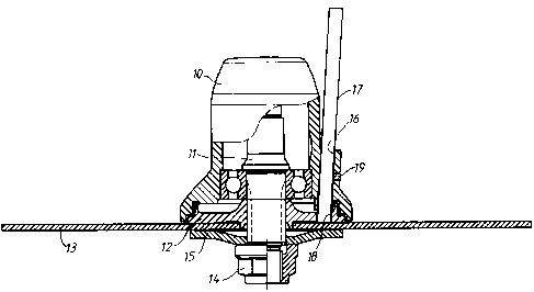
A housing 10, including an engine powered gearbox, is connected to a user-
held guide bar, not shown in the drawing, of a clearing saw. The gearbox
includes
a toothed transmission gear, not shown in the drawing, with a rotatably driven
shaft

CA 02335444 2001-02-12
3
11. A fastening device 12 for holding in place a cutting tool 13 is attached
to the
low end of the shaft 11 as shown. The cutting tool 13, for example a circular
saw
blade, is attached to the fastening device by a nut 14 screwed on to the
threaded end
of shaft 11, and an elastic washer 15. The nut 14 can be screwed off released
to
make it possible to replace the cutting tool 13.
The gearbox housing 10 has on one of its sides an almost vertical hole 16.
Inside the hole 16, a locking pin 17 is inserted, the pin 17 being made of a
magnetic
material, for example iron. The lower end of the locking pin 17 can be located
or
inserted in a matching opening or hole 18 in the fastening device 12. The
surrounding housing wall defining the hole 16 includes a magnet 19 located at
the
inner surface of the hole 16 to magnetically engage and be in contact with the
locking pin 17 when the locking pin 17 is inserted into the hole 16. The
magnet 19
is preferably a neodymium magnet to increase the magnetic force between the
magnet 19 and the locking pin 17 compared to an ordinary ferrite magnet.
In the drawing, the locking pin 17 is inserted into the aligned matching hole
18 in the fastening device 12, wherein the saw blade 13 and the shaft 11 are
all
locked and thereby not able to rotate. This makes it possible to unscrew the
nut 14
from the threaded lower end of shaft 11 with an appropriate tool. To make it
possible to insert the locking pin 17 into the hole 18, the saw blade 13 or,
if no saw
blade is attached, the fastening device 12, is rotated by hand until the
centerline of
hole 18 coincides with the centerline of the hole 16. After that, the locking
pin is
pushed into its locking position. The locking pin 17 will be kept in this
position by
the magnet 19, even though the gearbox is turned up side down to make it easy
to
screw or unscrew the nut to mount or unmount the saw blade. The cutting tool
is
therefore changed easily and without the risk that the locking pin 17 will
fall out of
its locking position. After the change of cutting tool, the locking pin 17 is
removed
from the vertical hole 16 or at least raised to an unlocking position, and the
machine
is ready to be used again. Since the described assembly to locate the pin 17
in its

CA 02335444 2001-02-12
4
locking position does not include any moving parts (other than the pin 17)
there is
only a minimum risk for locking assembly failure due to dirt, dust or other
debris.
It should be evident that this disclosure is by way of example and the various
changes may be made by adding, modifying or eliminating details without
departing
from the fair scope of the teaching continued in this disclosure. The
invention is
therefore not limited to particular details of this disclosure except to the
extent that
the following claims are necessarily so limited.

Representative Drawing
A single figure which represents the drawing illustrating the invention.
Administrative Status

2024-08-01:As part of the Next Generation Patents (NGP) transition, the Canadian Patents Database (CPD) now contains a more detailed Event History, which replicates the Event Log of our new back-office solution.

Please note that "Inactive:" events refers to events no longer in use in our new back-office solution.

For a clearer understanding of the status of the application/patent presented on this page, the site Disclaimer , as well as the definitions for Patent , Event History , Maintenance Fee  and Payment History  should be consulted.

Event History

Description Date
Application Not Reinstated by Deadline 2009-02-12
Time Limit for Reversal Expired 2009-02-12
Letter Sent 2008-03-18
Deemed Abandoned - Failure to Respond to Maintenance Fee Notice 2008-02-12
Inactive: Abandoned - No reply to s.30(2) Rules requisition 2008-01-16
Inactive: S.30(2) Rules - Examiner requisition 2007-07-16
Inactive: IPC from MCD 2006-03-12
Letter Sent 2006-02-22
Request for Examination Requirements Determined Compliant 2006-02-02
All Requirements for Examination Determined Compliant 2006-02-02
Request for Examination Received 2006-02-02
Application Published (Open to Public Inspection) 2001-09-10
Inactive: Cover page published 2001-09-09
Inactive: First IPC assigned 2001-04-24
Inactive: Filing certificate - No RFE (English) 2001-03-16
Letter Sent 2001-03-16
Application Received - Regular National 2001-03-13

Abandonment History

Abandonment Date Reason Reinstatement Date
2008-02-12

Maintenance Fee

The last payment was received on 2006-12-29

Note : If the full payment has not been received on or before the date indicated, a further fee may be required which may be one of the following

  • the reinstatement fee;
  • the late payment fee; or
  • additional fee to reverse deemed expiry.

Patent fees are adjusted on the 1st of January every year. The amounts above are the current amounts if received by December 31 of the current year.
Please refer to the CIPO Patent Fees web page to see all current fee amounts.

Fee History

Fee Type Anniversary Year Due Date Paid Date
Registration of a document 2001-02-12
Application fee - standard 2001-02-12
MF (application, 2nd anniv.) - standard 02 2003-02-12 2002-11-29
MF (application, 3rd anniv.) - standard 03 2004-02-12 2004-01-09
MF (application, 4th anniv.) - standard 04 2005-02-14 2005-01-24
MF (application, 5th anniv.) - standard 05 2006-02-13 2006-01-03
Request for examination - standard 2006-02-02
MF (application, 6th anniv.) - standard 06 2007-02-12 2006-12-29
Registration of a document 2008-02-11
Owners on Record

Note: Records showing the ownership history in alphabetical order.

Current Owners on Record
HUSQVARNA AB
Past Owners on Record
JORGEN JOHANSSON
Past Owners that do not appear in the "Owners on Record" listing will appear in other documentation within the application.
Documents

To view selected files, please enter reCAPTCHA code :


To view images, click a link in the Document Description column. To download the documents, select one or more checkboxes in the first column and then click the "Download Selected in PDF format (Zip Archive)" or the "Download Selected as Single PDF" button.

List of published and non-published patent-specific documents on the CPD .

If you have any difficulty accessing content, you can call the Client Service Centre at 1-866-997-1936 or send them an e-mail at CIPO Client Service Centre.


Document
Description 
Date
(yyyy-mm-dd) 
Number of pages   Size of Image (KB) 
Representative drawing 2001-08-27 1 9
Abstract 2001-02-11 1 13
Description 2001-02-11 4 181
Claims 2001-02-11 1 34
Drawings 2001-02-11 1 14
Courtesy - Certificate of registration (related document(s)) 2001-03-15 1 113
Filing Certificate (English) 2001-03-15 1 162
Reminder of maintenance fee due 2002-10-15 1 109
Reminder - Request for Examination 2005-10-12 1 115
Acknowledgement of Request for Examination 2006-02-21 1 177
Courtesy - Abandonment Letter (Maintenance Fee) 2008-04-07 1 175
Courtesy - Abandonment Letter (R30(2)) 2008-04-08 1 166
Courtesy - Certificate of registration (related document(s)) 2008-03-17 1 105
Fees 2002-11-28 1 44
Fees 2006-12-28 1 34