Sélection de la langue

Search

Sommaire du brevet 2335444 

Énoncé de désistement de responsabilité concernant l'information provenant de tiers

Une partie des informations de ce site Web a été fournie par des sources externes. Le gouvernement du Canada n'assume aucune responsabilité concernant la précision, l'actualité ou la fiabilité des informations fournies par les sources externes. Les utilisateurs qui désirent employer cette information devraient consulter directement la source des informations. Le contenu fourni par les sources externes n'est pas assujetti aux exigences sur les langues officielles, la protection des renseignements personnels et l'accessibilité.

Disponibilité de l'Abrégé et des Revendications

L'apparition de différences dans le texte et l'image des Revendications et de l'Abrégé dépend du moment auquel le document est publié. Les textes des Revendications et de l'Abrégé sont affichés :

  • lorsque la demande peut être examinée par le public;
  • lorsque le brevet est émis (délivrance).
(12) Demande de brevet: (11) CA 2335444
(54) Titre français: DISPOSITIF POUR OUTIL MECANIQUE PORTATIF
(54) Titre anglais: DEVICE IN A PORTABLE POWER TOOL
Statut: Réputée abandonnée et au-delà du délai pour le rétablissement - en attente de la réponse à l’avis de communication rejetée
Données bibliographiques
(51) Classification internationale des brevets (CIB):
  • B23D 47/00 (2006.01)
  • B27B 05/30 (2006.01)
  • B27B 05/38 (2006.01)
(72) Inventeurs :
  • JOHANSSON, JORGEN (Suède)
(73) Titulaires :
  • HUSQVARNA AB
(71) Demandeurs :
  • HUSQVARNA AB (Suède)
(74) Agent: SMART & BIGGAR LP
(74) Co-agent:
(45) Délivré:
(22) Date de dépôt: 2001-02-12
(41) Mise à la disponibilité du public: 2001-09-10
Requête d'examen: 2006-02-02
Licence disponible: S.O.
Cédé au domaine public: S.O.
(25) Langue des documents déposés: Anglais

Traité de coopération en matière de brevets (PCT): Non

(30) Données de priorité de la demande:
Numéro de la demande Pays / territoire Date
0000791-4 (Suède) 2000-03-10

Abrégés

Abrégé anglais


A locking assembly for a portable, engine-powered, hand tool, such as a
clearing
saw. To facilitate removal and installation of a rotatable cutting tool (13),
a rotatable shaft
(11) driving the cutting tool is locked against rotation by a movable locking
pin (17) of
magnetic material that is secured in a locking position by a magnet (19)
carried by a
housing of the tool supporting the rotatable shaft.

Revendications

Note : Les revendications sont présentées dans la langue officielle dans laquelle elles ont été soumises.


5
Claims
1. A portable, engine-powered, hand tool comprising:
a housing (10) with a rotatable shaft (11) releasable connected to a rotatable
cutting
tool (13), a locking pin (17) that is movable along its axis inside a hole
(16) in the housing
(10) and arranged for movement to a locking position to interfere with the
rotation of the
shaft (11) to lock the shaft (11) in a non-rotating position, characterized in
that a magnet
(19) carried by the housing retains the locking pin (17) in its locking
position to facilitate
removal and installation of the cutting tool on the shaft.
2. A tool according to claim 1, characterized in that the locking pin (17) is
made of a magnetic material and the magnet (19) is fastened to the housing
(10).
3. A tool according to claim 1, characterized in that the magnet (19) is a
neodymium magnet.
4. A tool according to any of claim 1-3, characterized in that a fastening
device (12) for the cutting tool (13) is attached to the shaft (11) and is
provided with an
opening (18) with an axial centerline that can align with an axial centerline
of the hole (16)
in the housing, wherein the locking pin (17) can be inserted into the opening
(18).
. A tool according to claim 1, characterized in that the housing (10) includes
a gear box for a clearing saw and the cutting tool (13) a circular saw blade.

Description

Note : Les descriptions sont présentées dans la langue officielle dans laquelle elles ont été soumises.

CA 02335444 2001-02-12
DEVICE IN A PORTABLE POWER TOOL
The present invention relates in general to portable, engine-powered, hand
tools, and more specifically, to a clearing saw with a changeable circular saw
blade.
Such tools include an engine, a housing and a rotatably drive shaft connected
to a
rotating cutting tool, such as a circular saw blade, that is releasable
fastened to the
end of the shaft. A locking pin is movable in an axial direction into a hole
in the
shaft, or a part attached to the shaft, to fix the shaft in a non-rotating
mode in
relation to the housing to facilitate installation and removal of the cutting
tool. In
portable, engine-powered, hand tools like clearing saws, the cutting tool is
fastened
to the shaft, extending from a gear box, for example, by a nut screwed on to a
threaded end of the shaft. In order to facilitate the changing of the cutting
tool, the
shaft must be stopped from rotating relative to the housing to make it
possible to
rotatably release or fasten the nut. The shaft is stopped from rotation by the
locking
pin that is moved into a position to interfere with shaft rotation wherein the
shaft is
blocked from rotating in relation to the gearbox. It is desirable to keep the
locking
pin in this locking position even if the machine is turned up side down or
otherwise
moved around so as to make it easier to change the cutting tool by unscrewing
the
nut.
There are different known methods to keep the locking pin in a locking
position wherein the shaft is not able to rotate. These prior art methods
utilize
mechanical latching solutions including multiple parts. Since clearing saws
work in
very rough conditions, the mechanical latching solutions do not always work
properly because of the dirt, dust wood particles, and other debris that can
interfere
with the mechanical latches during use. Another well known solution is to use
a
locking pin mounted in a hole in the housing and being under influence of a
biasing
spring that acts in an axial direction on the locking pin to hold it or bias
it in an
unlocking position. The locking pin is movable in an axial direction to a
locking

CA 02335444 2001-02-12
2
position and is mounted on the housing in such a manner that it will not fall
out of
the hole. The locking pin can be pushed into a locking position by the user by
pressing a finger against the pin with a force stronger than the biasing
spring. The
user must keep his finger on the pin to keep the shaft locked, otherwise the
pin will
return to its normal, spring-biased, non-locking position. This solution might
include a releasable stop device that keeps the pin in the locking position,
however,
such a mechanism would make the tool heavier and more complex.
The purpose of the present invention is to make a locking assembly of the
aforementioned type that eliminates the above-described prior art problems. A
tool
according to the subject invention would also be easier to handle, would work
better
in hostile environments, and would produce a tool at lower cost than the prior
art
solutions described.
In accordance with the invention, a portable, engine-powered hand tool, such
as a clearing saw with a rotatable blade mounted to an end of a rotatable
drive shaft,
includes a locking assembly for holding the rotatable shaft in a fixed
position during
installation and removal of the blade. The assembly included a locking pin
movable
along its axis between unlocking and locking positions. At its locking
position, the
pin interferes with rotation of a shaft to which the blade is mounted, to
thereby
facilitate installation and removal of the blade. The locking pin can then be
moved
to an unlocking position to permit normal use of the tool. In accordance with
the
invention, the locking pin is made of magnetic material. A magnet fixed to the
housing magnetically engages the pin to hold it at a locking or unlocking
position as
determined by the user.
A fuller understanding of the invention may be had by referring to the
following description and claims taken in conjunction with the accompanying
drawing.
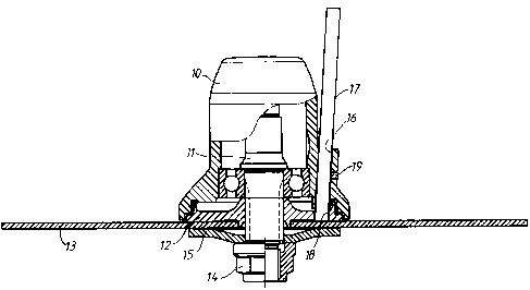
A housing 10, including an engine powered gearbox, is connected to a user-
held guide bar, not shown in the drawing, of a clearing saw. The gearbox
includes
a toothed transmission gear, not shown in the drawing, with a rotatably driven
shaft

CA 02335444 2001-02-12
3
11. A fastening device 12 for holding in place a cutting tool 13 is attached
to the
low end of the shaft 11 as shown. The cutting tool 13, for example a circular
saw
blade, is attached to the fastening device by a nut 14 screwed on to the
threaded end
of shaft 11, and an elastic washer 15. The nut 14 can be screwed off released
to
make it possible to replace the cutting tool 13.
The gearbox housing 10 has on one of its sides an almost vertical hole 16.
Inside the hole 16, a locking pin 17 is inserted, the pin 17 being made of a
magnetic
material, for example iron. The lower end of the locking pin 17 can be located
or
inserted in a matching opening or hole 18 in the fastening device 12. The
surrounding housing wall defining the hole 16 includes a magnet 19 located at
the
inner surface of the hole 16 to magnetically engage and be in contact with the
locking pin 17 when the locking pin 17 is inserted into the hole 16. The
magnet 19
is preferably a neodymium magnet to increase the magnetic force between the
magnet 19 and the locking pin 17 compared to an ordinary ferrite magnet.
In the drawing, the locking pin 17 is inserted into the aligned matching hole
18 in the fastening device 12, wherein the saw blade 13 and the shaft 11 are
all
locked and thereby not able to rotate. This makes it possible to unscrew the
nut 14
from the threaded lower end of shaft 11 with an appropriate tool. To make it
possible to insert the locking pin 17 into the hole 18, the saw blade 13 or,
if no saw
blade is attached, the fastening device 12, is rotated by hand until the
centerline of
hole 18 coincides with the centerline of the hole 16. After that, the locking
pin is
pushed into its locking position. The locking pin 17 will be kept in this
position by
the magnet 19, even though the gearbox is turned up side down to make it easy
to
screw or unscrew the nut to mount or unmount the saw blade. The cutting tool
is
therefore changed easily and without the risk that the locking pin 17 will
fall out of
its locking position. After the change of cutting tool, the locking pin 17 is
removed
from the vertical hole 16 or at least raised to an unlocking position, and the
machine
is ready to be used again. Since the described assembly to locate the pin 17
in its

CA 02335444 2001-02-12
4
locking position does not include any moving parts (other than the pin 17)
there is
only a minimum risk for locking assembly failure due to dirt, dust or other
debris.
It should be evident that this disclosure is by way of example and the various
changes may be made by adding, modifying or eliminating details without
departing
from the fair scope of the teaching continued in this disclosure. The
invention is
therefore not limited to particular details of this disclosure except to the
extent that
the following claims are necessarily so limited.

Dessin représentatif
Une figure unique qui représente un dessin illustrant l'invention.
États administratifs

2024-08-01 : Dans le cadre de la transition vers les Brevets de nouvelle génération (BNG), la base de données sur les brevets canadiens (BDBC) contient désormais un Historique d'événement plus détaillé, qui reproduit le Journal des événements de notre nouvelle solution interne.

Veuillez noter que les événements débutant par « Inactive : » se réfèrent à des événements qui ne sont plus utilisés dans notre nouvelle solution interne.

Pour une meilleure compréhension de l'état de la demande ou brevet qui figure sur cette page, la rubrique Mise en garde , et les descriptions de Brevet , Historique d'événement , Taxes périodiques et Historique des paiements devraient être consultées.

Historique d'événement

Description Date
Demande non rétablie avant l'échéance 2009-02-12
Le délai pour l'annulation est expiré 2009-02-12
Lettre envoyée 2008-03-18
Réputée abandonnée - omission de répondre à un avis sur les taxes pour le maintien en état 2008-02-12
Inactive : Abandon. - Aucune rép dem par.30(2) Règles 2008-01-16
Inactive : Dem. de l'examinateur par.30(2) Règles 2007-07-16
Inactive : CIB de MCD 2006-03-12
Lettre envoyée 2006-02-22
Exigences pour une requête d'examen - jugée conforme 2006-02-02
Toutes les exigences pour l'examen - jugée conforme 2006-02-02
Requête d'examen reçue 2006-02-02
Demande publiée (accessible au public) 2001-09-10
Inactive : Page couverture publiée 2001-09-09
Inactive : CIB en 1re position 2001-04-24
Inactive : Certificat de dépôt - Sans RE (Anglais) 2001-03-16
Lettre envoyée 2001-03-16
Demande reçue - nationale ordinaire 2001-03-13

Historique d'abandonnement

Date d'abandonnement Raison Date de rétablissement
2008-02-12

Taxes périodiques

Le dernier paiement a été reçu le 2006-12-29

Avis : Si le paiement en totalité n'a pas été reçu au plus tard à la date indiquée, une taxe supplémentaire peut être imposée, soit une des taxes suivantes :

  • taxe de rétablissement ;
  • taxe pour paiement en souffrance ; ou
  • taxe additionnelle pour le renversement d'une péremption réputée.

Les taxes sur les brevets sont ajustées au 1er janvier de chaque année. Les montants ci-dessus sont les montants actuels s'ils sont reçus au plus tard le 31 décembre de l'année en cours.
Veuillez vous référer à la page web des taxes sur les brevets de l'OPIC pour voir tous les montants actuels des taxes.

Historique des taxes

Type de taxes Anniversaire Échéance Date payée
Enregistrement d'un document 2001-02-12
Taxe pour le dépôt - générale 2001-02-12
TM (demande, 2e anniv.) - générale 02 2003-02-12 2002-11-29
TM (demande, 3e anniv.) - générale 03 2004-02-12 2004-01-09
TM (demande, 4e anniv.) - générale 04 2005-02-14 2005-01-24
TM (demande, 5e anniv.) - générale 05 2006-02-13 2006-01-03
Requête d'examen - générale 2006-02-02
TM (demande, 6e anniv.) - générale 06 2007-02-12 2006-12-29
Enregistrement d'un document 2008-02-11
Titulaires au dossier

Les titulaires actuels et antérieures au dossier sont affichés en ordre alphabétique.

Titulaires actuels au dossier
HUSQVARNA AB
Titulaires antérieures au dossier
JORGEN JOHANSSON
Les propriétaires antérieurs qui ne figurent pas dans la liste des « Propriétaires au dossier » apparaîtront dans d'autres documents au dossier.
Documents

Pour visionner les fichiers sélectionnés, entrer le code reCAPTCHA :


Pour visualiser une image, cliquer sur un lien dans la colonne description du document. Pour télécharger l'image (les images), cliquer l'une ou plusieurs cases à cocher dans la première colonne et ensuite cliquer sur le bouton "Télécharger sélection en format PDF (archive Zip)" ou le bouton "Télécharger sélection (en un fichier PDF fusionné)".

Liste des documents de brevet publiés et non publiés sur la BDBC .

Si vous avez des difficultés à accéder au contenu, veuillez communiquer avec le Centre de services à la clientèle au 1-866-997-1936, ou envoyer un courriel au Centre de service à la clientèle de l'OPIC.


Description du
Document 
Date
(aaaa-mm-jj) 
Nombre de pages   Taille de l'image (Ko) 
Dessin représentatif 2001-08-27 1 9
Abrégé 2001-02-11 1 13
Description 2001-02-11 4 181
Revendications 2001-02-11 1 34
Dessins 2001-02-11 1 14
Courtoisie - Certificat d'enregistrement (document(s) connexe(s)) 2001-03-15 1 113
Certificat de dépôt (anglais) 2001-03-15 1 162
Rappel de taxe de maintien due 2002-10-15 1 109
Rappel - requête d'examen 2005-10-12 1 115
Accusé de réception de la requête d'examen 2006-02-21 1 177
Courtoisie - Lettre d'abandon (taxe de maintien en état) 2008-04-07 1 175
Courtoisie - Lettre d'abandon (R30(2)) 2008-04-08 1 166
Courtoisie - Certificat d'enregistrement (document(s) connexe(s)) 2008-03-17 1 105
Taxes 2002-11-28 1 44
Taxes 2006-12-28 1 34