Note: Descriptions are shown in the official language in which they were submitted.
CA 02335626 2000-12-20
WO 99/67055 PCT/GB99/01906
APPARATUS AND N~THOD FOR GRINDING COMPOSITE WORKPIECES
Field of invention
This invention concerns methods and apparatus for grinding
workpieces which are composed of concentric in-line cylindrical
regions and intermediate non-axial non-circular or eccentric
regions. Examples of such workpieces are camshafts and
crankshafts of internal combustion engines and such workpieces
are referred to herein as composite workpieces.
Background to the invention
Because of the different techniques used for grinding in-line
and off-axis regions of workpieces, it has hitherto been
commonplace to grind the cylindrical region a composite
workpiece on one grinding machine and to transfer the workpiece
to another grinding machine for grinding the ncn-axial regions
such as cam lobes or crankpins.
With the trend towards lightweight engine components, camshafts-
and crankshafts have become less stiff and more prone to
distortion as a result of grinding forces exerted on the
workpiece by the grinding wheel particularly when high metal
removal rates are desired. To this end it has been proposed
to resist grinding forces exerted by the grinding wheel by
means of so-called worksteadies or workrests which engage
diametrically opposite regions of the workpiece without
inhibiting rotation, to resist the bending moment created by
the grinding wheel forces exerted on the workpiece.
In general the workrests have been applied against the journal
bearing regions of the workpieces, ie the cylindrical co-axial
regions of the workpiece which are normally intermediate non-
CA 02335626 2000-12-20
WO 99/67055 PCT/GB99/01906
2
circular or. off-axis components, such as the cam lobes and
crankpins of the exemplary workpieces.
It is an object of the present invention to provide a single
machine for. grinding composite workpieces.
It is a further object of the invention to improve the rigidity
of the mounting for a workrest as incorporated in such a
machine.
Summary of the invention
According to one aspect of the present invention in a grinding
machine comprising a stationary support structure, a wheelhead
assembly slidable relative to the said structure in a direction
perpendicular to a workpiece axis, headstock and footstock
means mounted on the structure and defining the workpiece axis,
rotating a workpiece mounted therebetween, at least one
workrest slidably adjustable along at least one rigid elongate
member or rail which extends generally parallel to the
workpiece axis, and programmable computer based control means
for controlling the movement of the wheelhead, the rotation of
the workpiece, and engagement and disengagement of the workrest
with a cylindrical region of the workpiece, wherein means is~
provided for fixing the workrest at a specific axial location
along the length of the said elongate rail so that the workrest
aligns with a cylindrical region of the workpiece.
During grinding, swarf, coolant and grinding medium particles
will be present in the environment around the interface between
the grinding wheel and the workpiece, and in order to prevent
any such material from reaching the sliding surface of the
elongate rail on which the workrest slides, and for axially
positioning the workrest along the rail, cover means is
provided on opposite sides of the workrest to keep any such
unwanted material away from the surface of the elongate support
rail therebelow, and prevent lateral movement of the workrest
CA 02335626 2000-12-20
WO 99/67055 PCT/GB99/01906
3
from its selected position.
The workrest and the cover means preferably form a linear
bearing with the rail.
Preferably the rail is made up of two spaced apart parallel
rails.
According to a preferred feature of the invention, each of the
covers forming the cover means is rigid and structural and
either adjustable in length or available in different lengths
to enable differently sized gaps measured parallel to the axis
of the workpiece to be covered by the covers, depending on the
desired position of the workrest.
The covers may be clamped in an axial sense so as to clamp
between them the workrest and position the latter along the
workpiece axis.
Where the sealing between the workrest and the cover means is
insufficiently reliable to prevent the penetration of fine
particle material and fluid, telescoping covers may be provided
below the rigid cover means which are sealed at least to the
opposite sides of the workrest and either extend sufficiently
far axially along the length of the elongate rail to prevent
the ingress of unwanted particulate or fluid material, or are
sealed at their opposite ends to end faces of support members
between which the elongate rail extends, thereby forming a
sealed enclosure within which the elongate rail is protected.
The telescoping nature of the inner covers enables the workrest
to be moved axially for adjusting its position along the rail
relative to the workpiece.
The telescoping inner covers may be in the form of bellows
which can extend or contract to accommodate axial movement of
the workrest along the elongate rail.
CA 02335626 2000-12-20
WO 99/67055 PGT/GB99/01906
4
The rigid covers are conveniently in the form of spacers and
may be tubular so as to wholly encompass the elongate member,
or C-shaped in cross-section to permit their insertion over and
removal from the elongate rail as required.
Typically a plurality of cover spacers are provided which fit
between the workrest and appropriate surfaces extending
perpendicularly to the elongate workrest support rail, so that
when fitted between the said surfaces and the workrest, the
latter is held rigidly and fixedly at a single axial position
along the support rail and therefore in axial fixed
relationship to the workpiece axis, so that the workrest will
always align with a similar region of each workpiece which is
mounted between the headstock and tailstock centres on the said
workpiece axis.
Typically the alignment is such as to correspond with a
cylindrical region of the workpiece near the mid-position of
the length of the workpiece measured between the two centres.
The invention is not limited to a single workrest but envisages
the mounting of two or more workrests along the said~elongate
support rail for positioning against other cylindrical regions
of a composite workpiece as aforesaid, such that as the said
other cylindrical regions are ground they can be engaged by a
workrest to resist sideways deformation of the workpiece as the
grinding wheel is forced against diametrically opposite regions
of the workpiece to grind the particular regions thereof.
Where a composite workpiece includes for example three spaced
apart cylindrical regions which are to form the inner surfaces
of journal bearings, three workrests are typically provided and
in this event four rigid covers are provided each of an axial
extent sufficient to just space the two outer workrests
accurately relative to the central workrest, and the two outer
workrests from fixed end faces at opposite ends of the elongate
support rail on which the workrests slide.
CA 02335626 2000-12-20
WO 99/67055 PCT/GB99/01906
Alternatively three such rigid covers may be provided for
spacing the first of the workrests accurately relative to the
headstock end of the workpiece, the second workrest relative
to the said first workrest, and the third workrest relative to
the second middle workrest, and clamping means is provided to
retain the third workrest axially in position along the
elongate rail and to maintain the assembly of spacing covers
and workrests between a face of the headstock (or a fixture at
the headstock end of the elongate rail), and the said clamping
means.
In addition or alternatively to the spacing achieved by means
of the said rigid covers, the workrests may include clamping
means, grub screws, wing nuts or other devices for securing
each workrest at a desired position along the length of the
elongate rail. However the spacing achieved by individual
accurately machined spacers each forming a cover for providing
at least partial protection for the elongate rail, may be
preferred, since this does not involve the need for individual
clamping or tightening mechanisms which could damage the
surface of the rail.
Preferably axial force is applied to the horizontal stack of
workrest(s) and spacers by means of a thrust member acting
through the tailstock so as to clamp the stack against a face
of the headstock assembly, or a structure associated with or
forming part of the headstock assembly.
In a method of setting up a grinding machine as aforesaid, the
workpiece may be replaced by a setting up bar having
cylindrical (journal bearing) regions machined therealong
corresponding to diameter and axial extent and axial positions
to the cylindrical (journal bearing) region of the workpiece
to be ground, and the workrests are positioned both axially and
radially so as to be appropriately positioned for engaging
similar workpieces as they are loaded successively onto the
machine.
CA 02335626 2000-12-20
WO 99/67055 PCT/GB99/01906
6
The thrust member may be in two parts separable by an actuator,
one part acting on the end of the stack through the tailstock,
and the other engaging a fixed structure such as a dressing
wheelhead assembly mounted on the machine bed. Spring means
may be incorporated in the thrust member.
Each workrest preferably comprises a housing which is slidable
along the elongate support rail and clamped in position
axially, and jaws which can be advanced and retracted relative
to the housing to engage a region of a workpiece. The jaws may
be driven in and out by electrical or pneumatic or hydraulic
drive means.
Where the workpiece is to be in axial compression independently
of the axial compressive forces acting on the stack, a
subsidiary housing containing the tailstock centre is slidable
and adjustably mounted on the main tailstock showing which
engage the said stack.
The invention is not limited to the grinding of one type of
composite workpiece but can be applied to a grinding machine
which under CNC control can move the wheelhead so as~to either
follow the eccentric throw of cam lobes of a camshaft, or the
circular rotation of crankpins about the central axis of a
crankshaf t , so as to permit the grinding of the j ournal bearing
regions as well as the cam lobes or crankpins of camshafts and
crankshafts.
In accordance with another aspect of the invention, in a method
of grinding a composite workpiece on a grinding machine as
aforesaid, cylindrical journal bearing regions of the workpiece
are first of all ground and after at least the first said
cylindrical region has been finish ground, a workrest is
engaged therewith, positioned as appropriate along the length
of the workpiece axis, and after the cylindrical regions of the
composite workpiece have all been ground, the wheelhead control
is altered, and each of the non-cylindrical regions of the
CA 02335626 2000-12-20
WO 99/67055 PGT/GB99/01906
7
workpiece are ground in turn, the workrest remaining in
position against the first ~to be ground of the cylindrical
regions of the workpiece during all of the subsequent grinding
operations of the workpiece.
Where the required stiffness can only be achieved by the use
of two or more workrests, an appropriate number of such
workrests are provided, and the control system is arranged to
move each of the workrests into engagement with cylindrical
regions of the workpiece after each said region is finish
ground.
Since the first cylindrical region of the workpiece has to be
ground without a workrest to resist the grinding forces, the
first grinding step is preferably performed at a lower material
removal rate and with reduced speed of advance of the grinding
wheel so as to reduce the grinding forces exerted on the
workpiece while the unsupported cylindrical region is ground.
According to a preferred feature of the method, after an
initial grind of the first cylindrical region, the workrest is
introduced against that region which is sti'1 to be finished
and the workrest is kept in position for the remainder of the
grinding of the first said region.
Other workrests can be introduced and engaged against other
cylindrical regions as they are ground in a similar way.
Once the workpiece has become supported by at least one
workrest, grinding speeds and material removal rates can be
increased within the limitations of the machine and grinding
medium, so that the overall grinding time of the composite
workpiece can be optimised. In particular the grinding of the
non-circular or off-axis regions of cam lobes of camshafts and
crankpins of crankshafts can be significantly increased in view
of the presence of the workrests, so that the finish grinding
of the non-circular and off-axis regions of a composite
workpiece can be very much quicker than would otherwise be the
CA 02335626 2000-12-20
WO 99/67055 PC'T/GB99/01906
8
case. This~advantage, coupled with the saving in time which
is realised by not having to demount a workpiece and remount
it on a new machine, means that the overall machining time for
a composite,workpiece is significantly reduced.
Where the workpieces are either hollow or have hollowed ends,
the headstock and tailstock centres may be in the form of
conical workpiece-engaging devices, and where drive is to be
transmitted to the workpiece this can be effected either by
means of a positive link such as a key, or chuck, or peg drive
where a peg enters an off-axis hole provided in the end surface
of the workpiece.
However according to a preferred feature of the invention,
where the workpiece does not have sufficient material in the
end face which is to be driven to provide notches or apertures
or openings for receiving pegs or other such driving devices
a method of driving the workpiece involves providing an axial
compressive force between headstock, workpiece and tailstock,
and providing a good friction fit between a driven centre
typically at the headstock and the hollow end of the workpiece
engaged thereon. Drive can be transmitted to the workpiece
with sufficient precision and lack of slip as to allow not only
the cylindrical workpiece regions to be ground but also the
circular and even off-axis regions to be ground, where the
driving torque required to maintain rotation of the workpiece
particularly during high metal removal rates, can be quite
considerable.
According to a preferred aspect of this last feature of the
invention the surface of the driving cone is preferably
impregnated with diamond grit so as to provide a very hard but
precision surface for engaging in a central circular opening
in the end of a composite workpiece as aforesaid, and the axial
compressive force exerted between the workpiece and the centres
at the opposite ends of the workpiece, is sufficient to cause
the grit to bite into the end surface of the workpiece material
CA 02335626 2000-12-20
WO 99/67055 PC'T/GB99/01906
9
and accurately centre, and resist any relative movement
between, the workpiece and the conical driving cone.
Since accurate circular indexing of a composite workpiece is
needed to allow the CNC control of the wheelhead to enable non-
circular and off-axis regions to be accurately ground, the
workpiece must either incorporate an index mark which can be
detected by means of a suitable optical or other sensing device
associated with the grinding machine, to provide an index
signal to the programmable computer based control system, or
a vee notch indexing device may be provided under the control
of the computer based control system which after the
cylindrical regions have been ground, is advanced so as to
engage around one of the non-circular or off-axis components,
and after centering the component relative to the notch,
provides a zero position for a rotatable indexing device
associated with the workpiece drive, to allow accurate indexing
of the workpiece thereafter under computer control, to present
first one and then another of the non-circular or off-axis
regions for grinding.
Since the different cylindrical and non-circular or~off-axis
regions are located at different axial positions along the
length of the workpiece, means is provided for indexing the-
wheelhead relative to the workpiece or the workpiece relative
to the wheelhead so as to enable the grinding wheel to address
different regions of the workpiece as required.
Whilst the arrangement of cover means or spacers serves to
accurately and firmly locate the workrests relative to the
workpiece, there may occur a lack of rigidity in a plane
perpendicular to the elongate rails, ie in the form of sway of
the workrests. Also crabbing movement along the rails can
result in misalignment of the workrests relative to the axis
of rotation of the workpiece.
According to a further aspect of the present invention, such
CA 02335626 2000-12-20
WO 99/67055 PC'f/GB99/01906
undesirable~movement of the workrests relative to the rail can
be obviated by providing for a~ clamping engagement between the
workrest and one of the rails, the clamping being effected
after the workrest has been slid into position along the rails,
to retain the workrest in that position during the machining
operation.
Where one of the two rails underlies the jaws at the front of
the workrest and the other rail underlikes the rear of the
workrest, the clamp preferably engages the rail.
Preferably a first bearing assembly is provided below the front
of the workrest for running on the front rail.
Undesirable crabbing of the carriage relative to the front rail
can be avoided by incorporating roller bearings in the said
first bearing assembly.
Preferably the cross-section of each of the rails is in the
form of an I-beam, and the first bearing assembly located below
the workpi ece engaging jaws i s adapted to engage opposite sides
of the rail.
Preferably the shoulders of the upper and lower enlarged
regions of the rail taper towards the narrow stem of the rail
and. the first bearing assembly includes rolling elements which
are set at angles to complement the trapezoidal shape on each
side of the rail.
In the case of the rear rail, a second bearing arrangement is
provided which is adapted to engage one side of the rear rail
and a moveable member is adjustably secured to the carriage for
engaging the opposite side of the rear rail, and means is
provided for tightening the movable member against the rear
rail to clamp the rail between the fixed and movable members.
Preferably a clearance is provided between the rail which is
CA 02335626 2000-12-20
WO 99/67055 PC'T/GB99/01906
1Z
to be clamped and the various surfaces of the second bearing
arrangement to permit free travel when the clamping member has
been disengaged from the rail and is in its unclamped
condition. ,The sliding movement of the workrest is therefore
governed by the engagement between the first bearing assembly
and the front rail, and preferably a low friction engagement
is ensured with lubrication as appropriate.
Preferably pre-loaded rolling bearings providing high stiffness
are utilised.
The bearings may be double-sealed and/or axial sealed.
Conveniently the bearings on the rails are double wiped.
A preferred bearing assembly comprises the IKO LRXDC35.
A preferred rail comprises an IKO linear stainless steel rail.
Preferably a bearing seal assembly is provided around each
bearing assembly and rail associated therew~.t:;, to prevent the
ingress of dirt and/or mechanical particles.
The invention is not limited to the use of a single grinding
wheel, but may be adapted to multiple grinding wheels enabling
two or more regions of the workpiece to be ground
simultaneously.
Brief description of the drawinc3s
The invention will now be described by way o= example with
reference to the accompanying drawings in which:
Figure 1 is a perspective view of part of a grinding machine
adapted to provide workpiece support during grinding a
composite workpiece such as a crankshaft or camshaft of an
internal combustion engine;
CA 02335626 2000-12-20
WO 99/67055 PCT/GB99/01906
12
Figure 2 is a similar view from the opposite side of the
machine of Figure 1 with the wheelhead removed;
Figure 3 is.a plan view of the machine shown in Figure 1;
Figure 4 is a cross-section on the line AA of Figure 3;
Figure 5 is a cross-section on the line BB of Figure 3;
Figure 6 is a rear view of part of the machine in the direction
of arrow C in Figure 3, with the workpiece replaced by a
setting-up bar;
Figure 7 is a cross-section looking towards the headstock
showing a workrest, a spacer guard and a workrest carriage;
Figure 8 is an end view of the headstock as viewed from the
workpiece showing workpiece driver, first spacer guard and
bellow end plate;
Figure 9 is a section through the front rail on which the
workrests slide, to a reduced scale; and
Figure 10 is a cross-section to Figure 5 showing a modified-
workrest mounting.
Detailed description of rFi ures
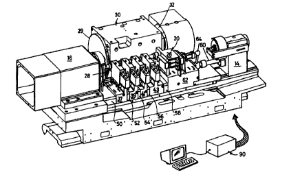
In Figures 1 and 2 a fixed base 10 provides a slideway 11 on
which a workslide 12 and dressing wheelhead 14 are slidable and
securable in position. A headstock assembly 16 is mounted at
one end of the base 10 and the latter is carried by a sub-base
17.
An electric motor 18 is housed within the headstock assembly
casing 16.
CA 02335626 2000-12-20
WO 99/67055 PCT/GB99/01906
13
A tailstock~assembly generally designated 20 is mounted on a
workslide 12 and a camshaft workpiece 21 is carried between a
driving chuck generally designated 22 at the headstock end and
in a chuck 24 carried by an upper section 26 of the tailstock
assembly 20.
A grinding wheel 28 protected by a cover 29 is carried by a
wheelhead assembly 30 to which is mounted an electric motor 32
for driving the wheelspindle and grinding wheel in rotation.
Although not shown, the wheelhead 30 is slidable along a
slideway which extends perpendicularly to the workpiece axis
and a further drive, either a feed screw or a linear motor (not
shown) serves to advance and retract the wheelhead under
computer control to allow the wheel to be brought into grinding
engagement with the workpiece and to move in and out in
synchronism with the rotation of non circular cam-lobe regions
(such as 34 in Figure 2) of the camshaft, ir_ manner known per
se.
In order to provide support for the camshaft during grinding,
four workrests 36, 38, 40 and 42 are mou.~.ted between the
headstock and tailstock assemblies, each comprising an
Arobotech Workrest Unit Type 3520. As will be described in
more detail with reference to later Figures, each of the
workrests is mounted on a carriage 37, 39, 4i an 43, and each
carriage is slidable on two parallel rails mounted on the upper
face of the workslide 12. This allows the workrests to be
adjusted in position along the length of the workslide 12.
Each workrest includes a pair of workpiece engaging jaws such
as 44, 46 as denoted in relation to workrest 36. Sliding of
the workrest carriage relative to the workslide enables the
jaws 44, 46 to align with a cylindrical (journal bearing)
region such as 48. As will be seen from Figure 2, the other
pairs of jaws engage the three other cylindrical journal
bearing regions of the camshaft 21.
CA 02335626 2000-12-20
WO 99/67055 PCT/GB99/01906
14
In order to accurately locate and space apart the workrest
carriages 37-43, cover-spacers 50, 52, 54, 56 and 58 are
sandwiched between the carriages and the opposed faces of the
headstock and tailstock (see Figure 1). Different spacings and
registration of the workrests is achieved by slacking off the
clamping force acting on the assembly of carriages and cover-
spacers, removing some or all of the latter and replacing them
with cover-spacers having a different width and reclamping the
assembly.
Clamping is most simply achieved by providing a thrust bar 60,
which may include a compression spring assembly, between the
fixed dressing wheelhead body 14 and the rear face of the main
housing 62 of the tailstock assembly 20, and providing an end
face on the headstock (which like the dressing wheelhead body
is fixed in position) against which the spacer 50 abuts. A
lever 64 is pivotable to increase and decrease the thrust
exerted on the clamped assembly. In use sufficient compressive
force is exerted on the assembly of cover-spacers and
workrests, to keep them fixed in position.
The plan view of Figure 3 shows how the thrust bar extends
along an axis which is approximately midway of the workrest
carriages so that when the compressive force acts on the main-
tailstock housing 62 there is little tendency to twist the
housing 62. Twisting is further reduced by arranging that the
carriages slide on two parallel spaced apart rails which are
equidistant about the straight line continuation of the axis
of the thrust bar 60.
Figure 3 also shows how the jaws of the workrests engage the
cylindrical regions of the camshaft and fit between the cam
lobes 34, 35.
In Figure 3 the grinding wheel 28 is shown grinding the cam
lobe 34.
CA 02335626 2000-12-20
WO 99/67055 PCT/GB99/01906
The section. on AA (Figure 4) allows the two parallel spaced
apart rails 66, 68 to be seen (in cross section) on which the
workrest carriage 43 slides by means of linear bearings 70, 72.
Also visible in cross-section is the end spacer 37. Fluid
connections are shown at 74, 76 by which air or hydraulic fluid
is conveyed to and from the workrest to drive the jaws 44, 46
in and out of the workrest housing, in the directions indicated
by the arrow 78.
The section on BB (Figure 5) shows the engagement of a
cylindrical workpiece region 80 by the upper and Lower jaws 82,
84 and an intermediate stop 86. The latter is that part of the
workrest which provides the reaction to the grinding forces
exerted by the grinding wheel on the workpiece. Each pair of
jaws of each of the workrests includes a step such as 86 shown
in Figure 5.
The rear view on arrow "C" in Figure 3 and which comprises
Figure 6, shows how a machined setting up bar 88 can be fitted
between headstock and tailstock preparatory to the replacement
of a camshaft workpiece. This allows the workrest positions
to be checked and the computer control system (item 90 in
Figure 1) to be initialised with position information relating
to the workrest jaws, to allow the latter to be advanced as
required during grinding to just the correct positions to
engage similar cylindrical regions of a camshaft.
Figure 7 shows how the rails 66, 68 are screwed to the
workslide 12 as by screw 92.
Below each of the cover-spacers, which serve to protect the
rails and linear bearings associated therewith, are located
bellows assemblies. Each assembly has a plate at each end for
attachment to the opposed end faces of adjacent workrest
carriages or the headstock or tailstock. One such bellows
endplate is shown at 94 in Figure 8. This is in fact an end
plate of the bellows which fits between the end face of the
CA 02335626 2000-12-20
WO 99/67055 PCT/GB99/01906
16
headstock carriage 96 (also denoted in Figure 2), and the
opposed end face of the workrest carriage 37 (not shown in
Figure 8), below spacer 50. Pairs of screws or rivets
designated 98 and 100, secure the bellows endplate to the
headstock end face 96.
Figure 9 is an enlarged scale section through the front rail
68 shown secured in place by a plurality of screws 102, 104
etc. The bellows described with reference to Figure 8 can here
be seen at 106, 108, 110, 112 and 114.
The bellows assemblies further seal the sliding surfaces of the
rails and linear bearings against swarf and other grinding
media.
The cover-spacers may be sealed longitudinally to surfaces of
the rail supporting structure as well as being sealed against
the end faces of the workrests (or workrest carriages) and the
headstock and tailstock housings.
Figure 10 is similar to Figure 5, and shcws a proprietary
wvrkrest 116 with work engaging jaws 118, 120 and 122, mounted
on a carriage generally designated 124.
The carriage runs on two rails 126 and 128 the cross-section
of each of which is similar to an I-beam and the enlarged upper
and lower sections are pointed by a narrow vertical stem and
the shoulders of the upper and lower regions taper to the stem
to provide linear inclined faces such as 130 and 132 in the
case of rail 128.
Complementary inclined bearing surfaces are provided by four
rows of cylindrical rollers 133 in a roller bearing assembly
such as 134 secured to the underside of the carriage 124.
The inside faces 136, 133 of the other rail are similarly
engaged by a slider generally designated 140, and its outer
CA 02335626 2000-12-20
WO 99/67055 PCT/GB99/01906
17
inclined faces are engaged by correspondingly inclined faces
of a clamping member 142 of~generally C cross-section, the
upper end 144 of which is received in a parallel slided slot
146 for locating the member 142 relative to the carriage 124.
The Lower end generally designated 148 can be urged inr_o
engagement with the opposite inclined faces 150 and 152 of the
rail 126 by screwing in a threaded bolt 154 the head of which
forces the clamping device 142 into engagement at one end with
the slot 146 and at its lower end with the inclined faces 150
and 152.
The act of tightening the bolt 154 thus jams the rail 126
between the slider 140 (itself attached to the underside of the
carriage 124) and the lower end 148 of the C-shaped clamping
device 142.
The clamping so effected not only restricts the tendency for
the carriage 124 to slide along the rails 126 and 128, but also
removes any tendency for the carriage 124 to rock about either
of the rails.
The clamping action therefore restricts swaying or rocking of
the carriage 124 relative to the rails, and particularly
restricts rocking movement about the rail 128 in a plane'
perpendicular to the rails (ie within the plane of the sheet
containing Figure 10).
The slide 140 conventionally comprises one half of a roller
bearing assembly similar to item 134 as provided for running
on the front rail 128.
By providing for a roller bearing engagement with at least rail
128, such as by using an IKO roller bearing assembly type
LRXDC35 made by Nippon Thompson Co. Ltd. of Tokyo 108, Japan,
any tendency to crabbing movement of the carriage 124 relative
to the rail 128 is largely eliminated.