Note: Descriptions are shown in the official language in which they were submitted.
CA 02335866 2000-12-21
W0 00/05421 PCT/US99/16631 -
BLAST FURNACE WITH NARROWED TOP SECTION AND METHOD OF USING
BACKGROUND OF ~('HE INVENTION
This invention relates to an apparatus and method for efficiently converting a
diverse material input into useful,by-products and energy with a minimum of
waste
and pollution.
It has now been discovered how the design of mankind's two oldest large
industrial tools, the blast furnace and the slagging-ash gas producer can be
combined
into that of a Zone Controlled Multi-Purpose Slagging-Ash Oxygen Jet Blast
Converter (Improved Converter) which as the primary converter in an integrated
closed loop, can help solve some universally urgent problems by directly or
indirectly
completely converting a. wide range of materials, including in its four modes
of
operation: wastes, non-premium carbonaceous materials, oil shales and metallic
oxides into desirable needed products. It has the best characteristics of both
parents
plus some attractive unique ones while minimizing undesirable characteristics.
Both parents since prehistoric times, even when their construction was crude,
have been safely converting at high temperatures all the raw materials charged
in at
the top into molten metals and molten stags, gases, vapors and dusts, but
conventional
blast furnaces when they produce one ton of molten pig iron still produce
approximately six tons of an inferior 70-90 Btu/cf. top gas. Further, today's
Large
capacity blast furnaces function well only i~rhen charged with premium raw
materials
2:5. and the designs of conventional slagging-ash converters of all kinds
being used have
CA 02335866 2002-02-04
69275-151; S'
never been modernized to E;rovide a method of precisely regulating the
conversion
activities taking place as the charge entering at the top moves down
counterflow to the
gas stream generated near the bottom by a mainly hot air blast.
There currently is a need for conversion systems that convert substantially
100%
:l of all the input materials into desirable outputs. 'The health of the world
is being
increasingly threatened by air, water and land pollution related to the
generation and
disposition of wastes of marry kinds by dumping, burying, incinerating, and
releasing
them into the air. Conve:si~on residuals such as nitrogen oxides,
hydrocarbons,
sulfurous gases, and chemical compounds with a soluble toxic chemical content
are
polluting our air, land and °~ater. Nature's live plant converters are
being poisoned
by the chemical content of acid rain and smog produced mainly when petroleum
products and coals of all kinds are burned and the fumes released into the
air.
Commonly used high Btu content fuels are producing nitrous oxides which are
especially dangerous because of their depleting effect on the ozone layer.
Crude oil
reserves are rapidly being depleted and employing atomic energy to produce
electrical
energy has created serious new pollution problems.
U.S. Patent Nos. 3,814,404, 3,928,023, 4,381,938 and 4.495,054,
all introduced the :;oncept of regulating
activities within three temperature controlled zones in the blast furnace by
installing
:?0 strategically located auxiliary tuyeres openings in the side of the
furnace) through
which gases and other materials can be injected or withdrawn. The basic
objective,
except in U.S. Patent No. 4,4'97,0S4 was to produce molten metal from metallic
oxide
ores by employing less high temperature reducing gas generated internally from
premium coke prepared externally from superior coals. U.S. Patent No.
4,495.054
CA 02335866 2002-02-04
69275-151(S)
describes how ~ blast ;urnace c:.~ be improved into a zone controlled slagging-
ash l;as
producer. It recognized the desirability of employing a f 00% oxygen blast but
described no method of protecting the gas producei s refractory walls from the
high
flame temperatures such a practice produces. U.S. Patent No. ~.~81,938
describes an
improved blast furnace able t~~ cunction as either a blast furnace or a
slagging-ash gas
producer.
This invention involves itnprovements on these zone control concepts in order
to maximize performance of the blast furnace and achieve other desired
results.
SUMMARY OF THE INVENTION
The present invention is directed to a converter, a blast furnace modernized
in
such a manner as to make it practical to safely and effectively continuously
employ
a 100% oxygen jet blast and be operated so as to consume, by conversion, a
wide
range of mostly non-premium raw materials including wastes of many hinds
including
a wide range of toxic and hawdous wastes, oil shales and sands and other
inferior or
diffcult to process economically in an ecologically desirable manner raw
materials.
These are converted into fuel gases, molten metal, molten slag, vapors and
dusts.
Some conversion products are useable as produced and the balance are converted
in
the other production units in the system. A process control computer and
auxiliary
tuyere inputs and outputs are employed to precisely regulate the temperature
controlled activities taking place in the three converter zones and the
quality of the
outputs. Sensors are located at each of the five tuyere sets and at the top
and bottom
which are input to the process control computer. Gas samples are taken at
tuyere sets
T3, T4 and T7. These results are input to the process control computer giving
it the
-3-
CA 02335866 2002-02-04
69275-151(S)
information required to schedule periodic purges through the
appropriate tuyere sets when <~n undesirable build up of
recycling materials has occurred.
The invention may be summarized as in a blast
furnace for processing a charge of material introduced into
the top of the blast: furnace, the material being heated as
it moves downwardly through the widening, tapered stack of
the blast furnace, the p_rnprovement wherein the stack has a
narrowed top section wh~_ch cornpri.ses approximately 15
percent of the stack he~_ght above the bush and has a
substantially constant diameter on the order of
approximately 75 percent. of the diameter that the uppermost
portion of the stack wou:Ld hare i.f the taper of the stack
were maintained substantially constant.
In a preferre~:f embodiment wherein tuyere set Tl is
located in the hearth above where molten slag and metal are
allowed to collect, tuy~:re sei_ T2 is located above tuyere
set T1, tuyere set T3 i:~ locai~ed above tuyere set T2 and
above the mantel, tuyere set T4 i.s Located above the mantel
approximately 25 percents of the distance between the mantel
and the top cf the stack, and tuyere set T5 is located
approximately 42 percent= of the distance between the mantel
and the top of the stack.
According to anothe r aspect the invention provides
a method of operating the blast furnace as a converter
comprising the steps of a. ch<3rgi.ng into the top the solid
materials to be converted including carbonaceous materials
said material moving downward:Ly through the stack forming a
carbonaceous grate in the bosh; b. injecting through tuyere
--4-
CA 02335866 2002-02-04
69275-151(S)
sets T1 and T2 all incoming gases, liquids and dusts; c.
introducing 1000 oxygen jet b:Last. streams (with a peripheral
content of endothermic rwacting material) through jet
nozzles located in tuyere set T2 at a pressure high enough
to enable them to penetrate deeply into the bosh in front of
tuyere set T2; d. combu:~ting .in the bosh in front of tuyere
set T2 carbon from the ca rbonacec>us grate at high flame
temperatures to furnish the process heat required to convert
all input materials into a gas, vapor, molten metal, molten
slag or dusts; e. introducing through tuyere set T1
endothermic reacting rc.at~eriala at: a pressure slightly
greater than that prevailing :in t:he bosh to maintain a zone-
controlled temperature profile and create a temperature
controlled buffer zone :Located between the high temperature
more central portion of the bush and the walls in the lower
part of the converter to protect the refractories, the
tuyeres, and injectior,.:~ystems located there from the high
flame temperatures employed in the central portion of the
bosh; f. withdrawing cases, vapors and dusts through tuyere
sets T3, T4 and T5 to remove products and by-products and
achieve zone control of the converter's temperature profile;
g. withdrawing slag from the lower portion of the converter;
h. withdrawing metal from near the bottom of the converter;
and i. regulating the volume of endothermic reacting
2 ~~ materials input through tuyer~~ sE:ts '~ 1 and T2 and/or
regulating the Oz input through tuyere set T2 to control. the
temperature i.n the bo~,h.
According tc~ another aspect the method comprises
the steps of a. introclu~~ing a charge containing oil shales
or oil sands in which the carbonaceous material per ton of
oil shale or oil sand: will be within a ratio of about 0.6
-4a-
CA 02335866 2002-02-04
69275-151(S)
to 1.2; b. introducing endothermic reacting materials
through tuyere set Tl; c, introducing oxygen and an
additional peripheral l,_iyer of endothermic reacting material
through tuyere set T2; c~. burning the carbonaceous grate
material in said charge in the central portion of the bosh
to produce the heat req~zired t=o convert the down-moving
charge to gases, vapors, molten metal, molten slag or dusts
and to provide heat for steps ~~e." and "f."; e. heating the
charge near the top of stack, where the reduced diameter of
the stack starts to taper to t=he conventional diameter to
not above 480°C to start. releasing liquid kerogen and
expanding the oil shale portion c>f the charge; f. further
heating the charge at she bott=om end of stack to
approximately 1000°C to conve,_t the carbonaceous portion of
the charge tc coke or char and preheat t:he noncarbonaceous
portion of the burden; c~. furi=her heating the down moving
charge in the central portion of the bosh to a temperature
high enough to convert ur to gases, molten slag, molten
metal, vapors or dusts; h. rernovi_ng molten metal and molten
slag from the crucible; i. continuously withdrawing gases
through tuyere set T3 ~~ontain:ing rer_ycling materials; j.
withdrawing useful hydrocarbon gases and kerogen through
tuyere sets T4 and T5, and through the t=op of the stack.
According to another aspect the method is for
converting municipal and/or industrial wastes having a
metallic content into useful byprodur_ts, the method
comprising the steps cf.: a. introducing a charge containing
said wastes, carbonaceous material and slag-forming
constituents into the top of ~he furnace; b. introducing
endothermic reacting rr.ai.erial;s through tuyere set Tl; c.
introducing oxygen through tuyere set T2; d. burning the
-4b-
CA 02335866 2002-02-04
69275-151(S)
carbonaceous material in said charge in the central portion
of the bosh to melt slag therein and to provide heat for
step (e); heating the ~.:harge in the stack to approximately
1000°C to convert the c~~rbonaceous portion of the charge to
coke or char and convert= the noncarbonaceous portion to
gases, vapors and molten materials; f. removing molten metal
and molten slag from the crucible; g. withdrawing useful
gases through tuyere s~st T3 having an energy content of 280
to 300 Btu/cf; and h. wi.t;hdrawing useful gases through
tuyere sets T4 and T5, ~~nd through the top of the stack.
DESCRIPTION OF THE DRAWINGS
The invention is described by way of example in
the following detailed description, taken in conjunction
with the accompanying d:rawi.ng, in which:
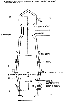
FIG. 1 is a schematic, cross-sectional view of the
converter according to the invention; and
FIG. 2 is a f~.ow diagram showing the "Improved
Converter System" incorporating a converter according to the
invention.
DESCRIPTION OF THE IMPROVED CONVERTER AND METHODS OF
fIDL~D S T TlIAT
The primary cc:mversion unit in "Improved Converter
Systems" will be a converter. The configuration almost
identical to a modern blast furnace except for the folic>wing
major improvements shown in Figure 1, Conceptual Cross
Section of converter. 'fhe largest diameter of the stack (at
the interface between zone #2 and zone #3) is reduced
approximately 25-30o in region 2, and in region 4 the stack
-4c-
CA 02335866 2002-02-04
69275-151(S)
5, tapers from the conventional diameter to the reduced
diameter. Region 4 extends from a point on the stack where
the temperature is contx-olled close to, but never above
480°C, to a point where the st=ack starts to taper at the top
of Region 4. Region 4 may ext=end from approximately 85~ of
the stack height above t:he bosh and to about 750 of the
stack height above the ~>osh. This modification prevents oil
shale or some carbonaceous grate forming materials, which
swell as they are coked, from prematurely absorbing enough
heat to begin expanding and creating a pinch point in
-~4d-
CA 02335866 2000-12-21
WO 00/05421 PCT/US99/I6631
this portion of the stack. T he solid materials are charged at the top of the
stack I 0 as
in conventional practice.
The five sets of tuyere sets are employed, so as to make it possible to create
and
more precisely control three distinct temperature zones of activity within the
:i converter. Gases, vaporized materials, liquids and dusts are input through
tuyere sets
TI and T2 in the bush 3 in Zone #I and withdrawn through three tuyere sets T3,
T4,
and TS and the top 9. The tuyere openings are located at strategic points in
such a
manner as to achieve a more precise than conventional converter temperature
profile
and/or extract products. Sensing devices are installed at the top and all f ve
tayere sets
i () and the crucible which are input converter temperatures at various
heights to the
process control computer along with the results of gas analyses of gas samples
taken
periodically at tuyere sets T3, T4, T5, and the flop.
Zone #1 is formed b:y injecting a computer-calculated amount of gaseous,
liquid,
vaporized or dust like endothermic reacting materials such as steam, carbon
dioxide,
1:p wastes in gaseous, liquid or dust forms, and hydrocarbons through an
endothermic
reacting material injection system placed in tuyere set TI located below
tuyere set T2.
Tuyeze set T2 is located where in conventional practice the hot air blast is
introduced
and is employed to introduce oxygen. It houses oxygen jet blast nozzles and a
peripheral injection system for endothermic material. The injection pressure
2n employed at TI tuyere set is variable but always only slightly greater than
that
prevailing in the bosh. An annular gaseous flame buffer, Zone #l, is created
in this
manner in front of tuyere sets TI .and T2. It protects the refractory walls in
this
portion of Zone #2 from the high flame temperatures. The materials injected
through
tuyere set TI tend to move up instead bf into the center of the bosh.
-S-
69275-15i(S)
CA 02335866 2002-02-04
Consuming the endothc:rrrac reacting peripheral content of the oxygen jet
blast
(which may be 100% oxygen; entering through the jet nozzles located in tuyere
set T2,
for a short distance prevents it from producing a high thame temperature as it
races
through Zone # I at a pressure much above (eg: up to double) that prevailing
in this
portion of the converter. The much larger endothermic reacting input through
tuyere
set Tl is converted to HZ and CO. The heat consumed by these endothermic
reactions
modifies the flame temperature in Zone t#1 enough to protect the refractory
walls,
injection systems and tuyeres in this area from the high flame temperatures
generated
in Zone #2 in front of tuvere set T"'.
Zone #2 is operated essentially as a high temperature process heat and
reducing
gas generation zone where the final conversion of the down moving burden to a
gas,
vapor, molten slag, or molten metal takes place. It includes all the bosh not
in Zone
#I. The oxygen consumption of the oxygen jet streams with their, peripheral,
endothermic reacting content, is minimal when they pass through Zone # 1. The
1 _'i streams mainly consume the carbonaceous grate in Zone 2 at high Name
temperatures
(2300° - 2600° C) which are conducive to the reactions C + O;=
CO= and C0, + C =
2C0 and HBO = H, t '/ O~. Zhese gases form the main ascending gas stream which
to a degree is modified in temperature by the endothermic input from Zone # 1
which
is maintained within a 800° - 1200°C temperature range by
regulating the
endothermic reacting input through tuyere sets T1 and T'_'.
Zone #3 starts at the cop of the mantel 8 and includes the entire stack. It is
regulated through three tuyere sets. Tuyere set T3 is located just (eg: about
2 feet)
above the mantel. The temperatures at this Level are regulated by the volume
of
oxygen input through tuverc: set T"_' and/or the endothermic reacting
materials input
-b-
CA 02335866 2000-12-21
- VVO 00/05421 PCT/US99/16631
through tuyere sets TI and T2. Tuyere set T4 is located above the mantel
approximately 25% of the distance between the mantel and the top of the stack.
The
temperature at Tuyere se~~ T4 is maintained near 850°C and the
temperature of the
transition section 4 at close to 480°C at the top end by regulating the
volumes of gas
S withdrawn through T3. Tuyere set T5 is located further up; the stack
(approximately
42% of the distance above. the mantel} where the stack temperature is
maintained near
760 °C by regulating the amount of gas withdrawn through tuyere sets T3
and T4. The
temperature at the top of t~he stack is maintained between 300° -
400°C by regulating
the volume of gas removed through tuyere T3, T4, T5 and the endothermic input
through T1 and T2. The; output 9 of a top gas collection system removes
gaseous
products of carbonization and/or volatilization, including carbon monoxide,
hydrogen,
hydrocarbons, hydrogen sulfide, oxides of sulfur, nitrogen, ammonium; light
oils, and
steam. The above locations as well as the Iocatian of the regions of the
improved
converter recited earlier generally can vary by 4% from the figure recited.
The cake and char constituents, which reform from above the carbonaceous
grate consumed in Zone #2 (except in the high volume molten metal production
mode), are internally manufactured in Zone #3 from non-premium coals and other
carbonaceous materials charged at the top and move downward by gravity as the
portion of the grate below them is gasified. Their temperature is controlled
by
regulating the amount of gas passed through the zone and its entering
temperatures so
that they are never Iower i:han 1000°C when they reach the bottom of
Zone #3. In this
way the traditional loss of sensible heat incurred when coke is produced
outside of a
blast furnace, then quenched and cooled before charging, is completely
avoided,
CA 02335866 2000-12-21
WO 00/05421 PCT/US99/16631
except when operating in the high molten metal production mode and then only
partially.
A typical medium size conventional blast furnace produces 2,500-3,150 tons of
hot metal (pig iron} while consuming 8,000-10,000 tons of solid charge
consisting of
iron bearing oxides, coke, and other additives. Source: Blast Furnace --
Theorv and
Practice, Volume 1, Gor<ion and Breach Science Publishers, New York; London,
Paris.
TABLE I
Blast-Furnace Dimensions
1 ~0 Hearth Diameter 29 ft 0 in
Bosh Diameter 32 ft 5in
Top Diameter 22 ft 6 in
BeII Diameter I6 ft 6 in
Hearth Bottom to Iron Notch 2 ft 0 in
Iron Notch to Cinder Notch 4 ft 8 in
Cinder Notch to Tuyeres 3 ft 6 in
Tuyeres to Bend Line 1 ft 4 in
Height of Bosh 11 ft 0 in
Height of Vertical Section 7 ft 0 in
*Height of Sloped Inwall 58 ft 0 in
Bend Line to Hopper Ring 22 ft 0 in
Total Height Iron Notch to Top Ring 108 ft 0 in
Working Height (Centerline of Tuyeres to 82 ft 0 in
Stockline, -6 ft Below barge Bell Closed)
Working Volume 51,500 cu ft
Bosh Angle 81 33' 22"
Inwall Batter I.03 In. Per. Ft.
No. of Tuyeres 24
Na. of Columns _ __ . 8
*Calcuiated Taper of Sloped Inwall 1.02 in/ft
An improved converter of this invention can exhibit nearly the same dimensions
as the referenced middle ;size conventional blast furnace with exceptions of
25-30%
reduced diameter of I 5% of the top stack height (ref. Fig 1 Region 2) and an
increased
tapered stack in Region 4 comprising approximately 10% of the stack height
which
_g_
CA 02335866 2000-12-21
WO 00/05421
PCT/US99/16631
interconnects with the top reduced diameter of the stack and the stack of
Region 5
exhibiting conventional constant tapper.
In addition to these modifications the improved converter employs five sets of
tuyere sets strategically located in the hearth and the stack above the bosh.
Improved
:5 converter dimensions and location of the tuyere sets can be as shown in
Table 2.
TABLE 2
Hearth Diameter 27 ft 0 in
Bosh Diameter 30 ft 6 in
Reduced Top Stack Diameter 12 ft 0 in
Reduced Diameter Top Stack Height 11 ft 6 in
Bottom Diameter of Tapered Stack Interconnection 20 ft 0 in
Height of Tapered Stack Interconnection 8 ft 0 in
(Region 4)
Stack Interconnect Taper r;Region 4) 5.6 in/ft
I _'> Height of Bosh 11 ft 0 in
Height of Vertical Section 20 ft 0 in
Height of Stack with Constant Taper 52 ft 0 in
Stack Constant Taper (Region 53 1.23 in/ft
Total Stack Height Top of the Bosh Top 71 ft 0 in
2Ci The Top Stack
Total Height iron Cast Hole to Top Stack 112 ft 0 in
Tuyere Set T, above Iron Casting Hole 7 ft 6 in
Tuyere Set TZ above Iron Casting Hole 12 ft 0 in
Tuyere Set T3 above Bosh 2 ft 0 in
25 Tuyere Set T4 above Bosh 18 ft 0 in
Tuyere Set _Ts~bove Bosh 29 ft 0 in
Dimensions of conve;ntional blast furnace and/or improved converter can vary
with the installed capacity..
30 CONVERTER SYSTEM(
By making the changes in the design of modern blast furnaces described herein,
and illustrated in Figure 1, it is practical to modernize them into converters
able to
operate effectively in four different modes depending on the major objectives
sought.
In two of the four modes they demonstrate their capacity as the primary
converter in
3 S universal Improved Converter Systems designed to completely convert, in
Mode # 1,
-9-
CA 02335866 2000-12-21
w0 00/05421 PCT/US99/16631
wastes of many kinds into desirable products and, in Mode #2, oil shales and
oil sands
completely into desirable products without causing pollution of any kind. In
Mode #3,
the converter functions as, an improved slogging-ash gas producer designed to
produce
a maximum volume of low cost clean burning gases from non-premium carbonaceous
S raw material sources without causing pollution. In Mode #4 the converter
functions
without causing pollution, as an improved (less coke consumed, no stove costs,
longer
lining life) high volume molten metal producing blast furnace also
simultaneously
producing a superior gas removed out the top (280 to 300 Btu/cf.).
In all modes a high finished product yield is obtained by completely
converting
I O alI incoming materials into a highly desirable boiler fuel gas, reducing
gas to feed
stack from which methanol is synthesized as withdrawn through tuyere set T3
with
only minor processing, or into gases, molten metal and slag vapors, and dusts
consumed in dependent production units in the fully integrated closed loop.
The high
flame temperatures used in the maximum temperature portion of Zone #2 produce
15 enough high temperature heat to completely convert all input materials.
Some of the other products withdrawn at tuyere sets T4 and TS, the top and the
slag notch 6 and casting; hole 7 are finished products as withdrawn. Others
can
constitute raw materials ss~reams to other production units in the integrated
Improved
Converter System where they are converted to f nished products. Referring to
Figure
20 2, these production units.include but are not limited to some combination
of Waste
Heat Boilers I I, I2, I3; a Ferrous Oxide Direct Reduction Plant 15; Steel
Making
Facilities I6; a Foundry I 7; a By-products Plant l 8; an Electrical Energy
Generation
Plant 19; a Processing into Building Materials unit 20; a Sulfur Products
Plant 2I a
synthetic polymer facility, such as a Synthetic Rubber or Fiber and Plastics
Plant 2$;
- IO-
CA 02335866 2000-12-21
WO 00/05421 PCT/US99/16631
a COZ rich atmosphere auperior food strain of Blue-green Algae Greenhouse Tank
Farm 22. Optionally another tandem operation converter 29 can be operated in
the
high molten metal production made. Supporting units include Material
Preparation
Plant 14, Endothermic Materials Storage 24: Oxygen Production Plant 2S and
S Nitrogen Storage 26.
The by-products stream is converted in the By-products Plant 18 into a variety
of products including, bust not limited to: a clean-burning pipeline gas with
a 400-600
Btu/cf. energy content; fertilizers; clean-burning fuels which will be ideal
substitutes
for gasoline, diesel fuel and jet propulsion fuel; a synthetic rubber, f ber
and plastics
products stream; industrial chemicals, and black top tar.
The Slag Processing unit 20 can produce, from the acidic slugs, superior
ingenuous rock castings, e.g., of an interlocking. type suitable for use in
residential
construction and other structures of many kinds. They are fireproof, insect-
proof,
require no maintenance;, have excellent insulating qualities and facilitate
rapid,
1 S low-cost construction. The basic stags, without remelting, can be
converted into
specification cements or rock wool insulation.
The Waste Heat Boilers 11, 12, 13 can produce steam; convert vaporous
kerogen to a readily processed liquid which, in the By-products Plant, can be
converted into substitutes for gasoline and other by-products; convert
recycling metal
vapors including sodiunn, potassium, and zinc to metallic dusts or droplets
and also
separate out NaCN and KCN. The Synthetic Rubber and Fiber Plant 28 can convert
the incoming raw materials stream from the By-products Plant into a wide
variety of
synthetic rubber, plastics, and fiber products.
-11-
CA 02335866 2000-12-21
WO 00/05421
PCT/US99/16631
In alt modes, except Mode #4, the high volume metal production mode, the
molten metal periodically withdrawn from the casting hole 7 in the
conventional
manner will be delivered to the Foundry I7 where any necessary separation of
the
different metals takes place or delivered directly to the steel making
facility.
To achieve the objectives set forth above, the converter has been designed and
is operated in any of the four modes so as to handle a very large volume of
diversified
materials charged in at the top 10. An average size converter is able to
process
approximately 8,000 to 10,000 tons of material per day. The size of the chunks
of
material charged normally vary from a minimum of 1/4" to a maximum of 8" in
any
I t7 one dimension.
When the major objective is disposal of wastes in an improved manner, the
materials charged at IO and those removed from the top 9, tuyere sets T3, T4
and T5,
the molten slag notch 6 and the molten metal casting hole 7 are somewhat
different
from the input and outputs when the main objective is to convert oil shaies
into
I _'> clean-burning fuels and many other benef cial products or convert non-
premium
carbonaceous materials into gases, or convert metallic oxide materials into
molten
metal. An essentially 100% oxygen jet blast is, however, employed in all modes
of
operation. It carries in witlh it a peripheral endothermic input as it is
released through
tuyere set T2 at a pressure lugh enough (eg: about double) above that
prevailing in this
20 bosh portion of the converter to make certain it passes rapidly through
Zone #1 and
penetrates deeply into Zone #2. The advantages of substituting a relatively
high
pressure 100% oxygen jet stream blast for the conventional hot air blast are
to: ( 1 )
eliminate the need for blast heating stoves; (2) impiove the movement of the
burden
down the stack by greatly reducing the ascending gas volume per 1b of carbon
- 12-
CA 02335866 2002-02-04
69275-151;~~)
consumed and by increasing tine ;:;;ntral portion of the carbonaceous grate
consumed;
(3) improve the quality of the gases praduced oy eliminating the nitrogen
content
introduced in the conventional hot air blast; 1,4) increase the generation of
high-temperature sensible heat by safely using high dame temperatures, and, as
a
consequence the magnitude of endothermic reactions that are practical; (5)
increase
the operating rate. Tlte gas connnuously removed through tuyere set T3 and
passing
through the Waste Heat Boiler and the Trace Sulfur Removal System to remove
vaporous materials will have a zeal energy content of 280-300 Btu/c::, making
it a
high efficiency boiler fuel, superior even to natural gars because it burns
with a lower
flame temperature and, consequently, no harmful nitrogen oxides will be
formed.
This gas is also an ideal raw material gas for use in synthesizing methanol
and other
products becatue it is almost entirely free of air-poisoning sulfur compounds,
hydrocarbons and nitrogen oxides formed when an air blast containing large
amounts
of nitrogen is employed.
Modes of Operation
When the major objective is to consume waste in an ideal manner, the charge
at the top 10 can contain waste materials of many kinds, including municipal
and
industrial wastes such as tires, automotive wastes, pesticides, sludges of
many kinds,
waste oil, PCBs and other hazardous and toxic, organic and inorganic
materials.
Unsorted municipal waste typically contains up to 3% (national average)
metallic
content. Enough basic slag constituents conventionally are added
to the charge entering through the top to produce the basic slag needed to
remove the
inorganic sulphur in the charer.=. To facilitate the production of
specification cement
-3-
CA 02335866 2000-12-21
WO 00/05421 PCT/US99/16631
clinker slag in the Slag Processing Into Building Materials Unit 20 chemical
additions
may be input into the more precisely controlled slag. The ratio of non-premium
coal
and other carbonaceous grate forming material charged per ton of wastes input
will
be relatively small; 0.25 to 0.7 because of the carbonaceous content of most
wastes.
The following is a calculated example illustrating this process for the
conversion
of municipal and industrial wastes into clean fuel gases and a basic slag
suitable for
conversion into specificaition cement clinkers and other by-products:
TABLE 3
.: . ' >. -' '.: :: ~? Q: ~ . : ,: .:
..: :.. .:: .:: ~ ~ ~~ . .:.::. . ..
:. . . ...:::: >:
. ~
1.0 Ibs lbs cf. BTUIcf.
Multiple Solid 1,400 T4, TS and 1,251 29,887 557 dry
Wastes Tap Gas
Tires 200 T3 1,592 28,809 300 dry
Sledges 100 Tar 53
Toxic Wastes 50 Light Oil 15
1.5 Slag Building 250 Pig Iron 118
Materials
Non-Premium Coal700 Non-ferrous 52
Metals
Commercial Oxygen715 Basic Slag 667
Steam 602 Water 35
Dust 35
2!0 TOTAL 4,017 T~TAL 4,017
The noncarbonaceous content of the charge as it descends is converted by
the ascending gas stream. to gases, vapors or molten materials which trickle
down
through the carbonaceous grate. The metals (mostly molten iron) accumulate in
~!5 the bottom of the hearth and a layer of slag forms on top of them. On
their way
down to the crucible the molten iron captures a maximum amount of the
inorganic
- 14-
CA 02335866 2000-12-21
WO 00105421 PCT/US99/16631
sulfur released when the: carbonaceous grate is consumed in front of tuyere
set T2.
It releases most of it to the slag layer as it passes through it.
Referring to Figure 1 it will be noted that the portion of the gas produced in
Zones # I and #2, which is not required in Zane #3 or which must be removed
through tuyere sets T4 a;nd TS to prevent an excessive buildup bf recycling
materials is withdrawn through tuyere set T3. Its temperature is closely
controlled
and its hydrogen and carbon monoxide content make it an ideal reducing gas to
use
externally without further processing; (Ref. U.S. Patent #4,381,938) in the
dependent zone-controlled molten iron producing blast furnaces 29, as a
substitute
l 0 for a portion of the gas which in conventional practice is generated from
the
combustion of blast furnace.quality coke, or in a Ferrous Oxide Direct
Reduction
plant I S the product from which is consumed by an electric arc furnace or
oxygen
blown converter 27.
In this mode of operation only minor ladle additions are required to produce:
1.5 a basic slag (suitable for manufacturing specification cements).
Approximately
400 to 700 pounds of slag is generated per ton of waste charged. Approximately
only one half of ali the gas generated in the bosh in Zone #2 is required in
Zone #3
to convert the carbonaceous portion of the charge to coke or char and either
put the
other materials into gaseous or vaporized farm or preheat them to
1000°C before
2:0 they reach Zone #2. Whf~n the output from tuyere set T3 is not used as a
reducing
gas it will be passed through wasteheat boiler 13 and trace sulfur removal
system
23. The emerging gas is an ideal clean-burning, high-efficiency boiler fuel
with a
280-300 Btu/cf. energy content. When it is consumed, e.g., in the Electrical
Energy Generation Plant 19, the stack gas composed almost entirely of C02, Hz0
-15-
CA 02335866 2000-12-21
WO 00/05421 PCT/US99/16631
and i~I2 (no nitrous oxide) is an ideal input into the Blue Green Algae
Greenhouse
Tank Farm 22 or its components may be separated in the By-products Plant and
the
COZ sold in some form or recycled as endothermic input to the converter
through
tuyere sets T1 or T2 or used in the By-products Plant 18 to synthesize
products.
When a pipeline quality gas is desired (400-600 Btu/cf.), all the materials
removed through tuyere sets T3, T4 arid TS and the top are delivered to waste
heat
boilers 1 l, 12 and 13 and then are sent to the trace sulfur removal system
23. The
total. gaseous output of the trace sulfur removal system 23 containing
products of
destructive distillation are sent to the By-products Plant I8, where pipeline
quality
1 ~0 gas is produced. The liquid output of the trace sulfur removal system 23
is
delivered to the Sulfur Products Plant 21. The molten metal formed is removed
periodically in the conventional manner and sent to the Foundry 17 where, if
necessary, the nonferrous metals are separated before the molten iron is
processed
to finished products in the Foundry 17 or delivered to the Steel Making
Facilities
1:S 16.
When the chemically and temperature controlled molten slag is periodically
withdrawn it is delivered to the Slag Processing Into Building Materials Unit
20.
There any additional chemical additions required to produce specification
cement
clinkers are stirred into the molten slag before it is cooled and ground into
cement,
20 or blown to produce rock wool insulation.
When the objective is a maximum output of clean-burning gases; the
converter is operated in Mode #3. The amount of carbonaceous material input at
the top 10 is increased. Much of the increase may be of biomass origin. The
material flow is the same as when operating in the waste conversion Mode # 1.
The
- 16-
CA 02335866 2002-02-04
09275-251 (S)
the top contains snore of the materials separated out in the By-products Ptant
and
sent to the Synthetic Rubber, Fiber and Plastics Plant 28.
When the objective is to convert oil shale or oil sands in a desirable manner
the converter is operated in Mode #2. The charge at the top 10 is oil shale or
oil
sands and non-premium coal or coke breeze in a ratio ranging from .6 to 1.?
per ton
of oil shale or sands. U.S. Patent 4,495,054 called attention to
a reported statist.i~= that in the U.S. alone, There
is one trillon of barrels of Iwerogen oil recoverable from oil shale. This
amount is
three times the world's known total crude oiI reserves. Kerogen can be refined
into
fuels which are superior to those made from crude oil. No additional slag-
forming
components are added, and the large volume of slag produced from the
conversion
of oil shale or oil sands is acidic. Approximately 70% of the gas generated in
Zone
#2 is required in Zone #3. The following is a calculated example of this
process for
extraction of kerogen, gases and other products from oil shale and
carbonaceous
a S materials:
CA 02335866 2000-12-21
WO 00/05421 PCT/US99/16631
TABLE 4
:::::::::::::.-...:::::::::<:::::::::::-:.::.......:::.:.:::::.:;:...;-
.~.:...:.:::::::.:::~ ....~._.~...~..,
.: :.::::.::...:::::.....::.~:::.,:.::::.~: ..:.:-..-..,::::::.. . ....
:.:::..:.~. ....: :: :.....:::::::.::-~... : . . .. ......
.;::::.:::.:::~>::::::>:::::::::.:.:::::::::::
:.:....:.::: ... .. .. ... . . .. . . : .
::.::::~ .-..:::.. .... ~~.,...:::....:::...:::::::............:..:..:.
~... :.. .. ....: ................................... ..........:
......... .. .....:........:.... :.~:::~..U~:~ .
.:::.:::::.........:::::::.:.:.........::::.:::
. .:......................... ..: ..
:::.~.::..:.::.::....:::<:::::::...~'.<..,:::::...::::.:;.;:::.::.::::...:.~::.
:...::::::.
.... ~. .: ......:.:::.....:........::....:~::..:....::::::
..... :.:::
. .: .....:.:
:::.~
lbs Ibs
Oil Shale* 2,000 T4, TS and 1,583 28,300 S00 dry
Top Gas
Non-Premium 1,500 T3 505 9,475 300 dry
Coal
Commercial Oxygen5Q5 Kerogen 228
S~~ ~ 445 Light Oil I 9
Tar 66
Pig Iron I 06
Acidic Slag 1581
Na (Metallic)52
K (Metallic) 12
Water 267
D~ 31
TOTAL 4,45U TOTAL 4,450
* D___~ _ ,.
-~wur~ Vil ~.=~Y~i~«° m vu ~nzue rrom largest U.:i. Oll shale deposit,
Green ItlVer
Basin - Colorado
As the, oil shale descends and the outside portion of each piece of shale
reaches 480°C it starts releasing liquid kerogen and expanding 50% by
volume.
McGraw-Hill Encyclopedia of Science and Technology, D. Van Nostrand
Company, Inc., New York, 1'976. The design of the improved converter according
to the invention accommodates the increase in volume of oil shales, and some
coals
which may be charged, as they reach their critical temperatures, by gradually
increasing the diameter of the stack in the Region 4, which tapers outwardly
from
the narrowed section 2 at the top. The more central consumption of the
carbonaceous grate, achieved by the more central delivery of the oxygen jet
blast,
also promotes an even down~~ard movement of the burden. As the coal and char
-18-
CA 02335866 2000-12-21
wo ooiasa~l
PCT/US99/16631
forming materials charged at the top descend, the moisture in the charge and
the
volatile components are driven off and leave the converter through the top.
The
coke or char remainder moves downward. As the liquid kerogen released in the
upper portion of Zone 3 descends it absorbs enough sensible heat from the
ascending gas stream to become vaporous and start ascending the stack again. A
portion of the ascending gas stream is continuously removed through tuyere
sets T4
and TS carrying with it a major portion of the kerogen vapor. When gas samples
taken at these points indicate an undesirable buildup in the stack, additional
carbonaceous material is. periodically charged and the output through these
tuyeres
1l0 increased to remove it. As the main portion of the gas stream formed in
Zone #2
moves up performing the coking process it also preheats approximately 1,500
lbs
of acid slag forming constituents produced per ton of oil shale or sands
converted.
Other materials that recycle in the stack interfering with the smooth
downward movement of the burden and decreasing lining fife are Na, K, KCN,
NaCN and Zn and P. Most of them are continuously output through Tuyere set T3.
When gas analysis shows the need, a periodic purge is made through tuyere sets
T3
and T4. The gases removed through tuyere sets T3, T4 and TS pass through Waste
Heat Boilers 12 and 13 and Trace Sulfur Removal System 23 before delivery to
the
By-products Plant or that from T3 sent elsewhere as desired. The products when
:?0 removed from the Waste; Heat Boilers are be in a liquid (kerogen and
water) or dust
form.
The iron oxide content of the oil shale is reduced in Zone #3. The reduced
oxides and the slag constituents become molten near the top of Zone #2, and
trickle
down through the carbonaceous grate in Zone #2. They accumulate in the hearth
- 19-
CA 02335866 2000-12-21
WO 00/U5421 PCT/US99/16631
and are periodically withdrawn as in conventional practice. The~acidic slag is
delivered to the Slag Pro<;essing Into Building Materials Unit 20, where it
can be
poured into igneous rock castings or processed into other building materials.
When it is desired; to use a converter to produce molten metal in an
S improved manner, mode ~#4 is employed. The charge at the top I0 will contain
metallic oxides in various forms. Only approximately 1/2 of the carbonaceous
grate material charged at the top need be premium blast furnace coke with the
stability required to resist: crushing by a burden heavy with iron or other
metallic
oxides. The balance of the carbonaceous requirement can be petroleum coke,
non-premium coal and optionally some additions of other carbonaceous material.
The effectiveness of this smaller amount of premium blast furnace coke is
enhanced because of the :reduced permeability requirements; (lower volume, no
nitrogen in the ascending gas), and other less costly carbonaceous materials
provide a major portion of the carbon consumed in producing the process heat
and
reducing gas required.
The following is a calculated example of the process for molten metals
production:
- 20 -
CA 02335866 2000-12-21
_ WO 00/05421
PCT/US99/16631
TABLE S
CHARGE P.RODLI.CT
Ibs Ibs cf. BTU/cf.
Coarse Iron Ore 902 Pig Iron2,000 -- __
Pellets -1,365Siag 766 -- __
Sinter 1,182 Top Gas 2,851 36,738 278
"B" Scrap 100 Water 559
Bosp Slag I51 Dust 59
Loss
Lime Stone 25
Metallurgical 600
Coke
Form Coke or 400
Pet. Coke
Biomas 140
Oxygen (Commercial)740
Steam
(Internally Produced)630
TOTAL 6,235 TOTAL 6,235
There are inherent advantages to converting molten metal producing blast
furnaces to converters: less premium coke per ton of molten metal, the
simultaneous production of a superior top gas, more tons of molten metal per
hour
longer lining life and the ability to consume tainted water and other
endothermic
inputs. The end result is .a lower cost per ton of molten metal produced and
less
polution. it is possible to gain these advantages by installing only the Zone
#1 and
#2 improvements detailed herein but even when superior raw materials are
charged
some will contain trace constituents which tend to cause recycling
complications
and shorten lining life. To gain full advantage, tuyere sets T3, T4 and TS
also need
to be installed along with the sensors located at strategic points which input
to the
_21 _
CA 02335866 2000-12-21
WO 00/05421
PCT/US99/16631
process control computer for calculation of the endothermic and exothermic
inputs
and outputs: When steann is input, the water gas reaction converts it into
carbon
monoxide and hydrogen. The hydrogen content of the up moving reducing gas
stream is increased, resulting in an increased steam and decreased carbon
dioxide
content in the top gas. In this mode, all gases leave through the top 9,
except
during periodic short intervals of recycling material removal. After the
moisture
and the sulfur is removef, the fuel gas formed will have an energy content of
280-300 Btu/cf. During brief recycling material purges; gas and vapors are
withdrawn through tuyere sets T3, T4 and T5. The process control computer
11~ calculates the additional premium blast furnace,coke to be charged. The
combustion of this coke is required to replace the sensible heat and reducing
gas
lost to parts of Zone #3 a~; that time.
When the major objective is to produce electrical energy without polluting
land, air or water, the converter is operated in either Mode #1 or Mode #3.
The gas
1 a withdrawn through tuyere set #3 after going through the Waste Heat Boiler
and the
Trace Sulfur Removal System is input into an Electrical Energy Generation
Plant.
The stack effluent from the plant's boiler is input into the By-products
Plant. There
it is separated into its components: nitrogen, carbon dioxide and water. The
Nz and
COZ and H20 may be sold as products, or the COz alternatively may be converted
2() in the By-products Plant to urea then used in the synthesize of
fertilizers and other
products. An alternate method is to deliver the top gas to a Blue-Green Algae
Greenhouse Tank Farm. There the algae in the pond employ photosynthesis to
convert the COZ into a health stimulating plant food and pure 02. Still a
further
option is to use the COZ as the endothermic input through tuyere sets TI or T2
in
-22-
CA 02335866 2000-12-21
_ WO 00/05421
PCT/US99/1663i
the converter. Steam froim Waste Heat Boilers 1 l, I2 and 13 is another
product
sold or used in the Electrical Generation Plant or elsewhere in the "Improved
Converter System".
The constructionvand operation of the converter of this invention employ
S only conventional materials and techniques and, given the teaching of this
specification, are easily within the skill of the art. Similarly, the
associated systems
and associated devices such as injection devices, temperature, liquid and gas
detection and analysis equipment, and the like, are commercially available.
Computer control systems are also available or can readily be formulated.
The preferred embodiment of the invention as described in the specification
and shown in the drawing; is illustrative only. Since modifications will be
apparent
to those skilled in the art, the invention is limited only by the scope of the
appended claims.
- 23 -