Note: Descriptions are shown in the official language in which they were submitted.
CA 02335930 2000-12-21
WO 00/67244 PCT/IT99/00392
Descri tin
LIGHTED PANEL DEVICE ABLE TO BE APPLIED ONTO POSTS
Technical Field
The present invention relates to a lighted panel able to be applied onto
posts, in
particular posts for road li!~hting or the like. The device is destined to the
display of
advertising and/or notices or communications also of public utility.
S
Bacl~,eround Art
In current urban decor. especially in lar;e cities. lighted panels can be
widely
observed. They generally present ample planar surfaces, mounted, generally
opposin~~
each other, on support elements of various shapes and sizes, bearing images
and/or
captions back-lighted with light sources, generally fluorescent or
incandescent lamps
situated between such planar surfaces in a box-like ci>ntainer. The purpose of
the
lighted panels is to make more visible at a distance advertising or
informational
posters placed on the planar surfaces than they would be if they were lighted
by
incident light alone, in order more effectively to attract the attention of
motorists and
~5 pedestrians during night-time hours.
To allow back-lighting, the light sources. usually the so-called neon lamps,
are
sandwiched between said planar surfaces, generally made of clear plastic
material.
This known type of lighted panels with back-lighted surfaces presents some
drawbacks. tn them, illumination is not distributed uniformly over the entire
surface
2o to light and therefore causes the poor definition of the contours of the
images or
captions to be lighted. A poor level of visual quality is determined, thereby
weakening the communication effectiveness of an advertising message. Moreover,
the luminosity of known panels, with the strong contrasts of the light that
exits
therefrom, creates a blinding or in any case an annoying effect for those who
watclj,
CA 02335930 2000-12-21
WO 00/67244 PCT/IT99/00392
2
whilst too weak a light leads them to turn their gaze away from the image or
caption.
Additionally, current structures for the display of advertising posters
require ample
display surfaces and need scaffolding, frames, uprights, and other bulky
support
structures, which generally have the tendency to influence negatively on a
landscape
and, in particular, on an urban decor. The costs of these lighted panels are
increased,
in addition to the provision of such structures, also by the need to connect
them to an
adequate electrical power supply. Moreover, current lighted panels are
unidirectional,
in that they are visible only frontally, unless arched panel surfaces, visible
ti'om
multiple directions, are created.
Disclosure of Invention
The aim of the present invention, therefore, is to overcome the aforementioned
drawbacks manifested by prior art lighted panels.
In particular an aim of the present invention is to allow the uniform lighting
of
I S images and/or captions.
Another aim of the present invention is to create an illumination of images
and/or
captions which does not cause annoyance to motorists and pedestrians, and
which
complies with the provisions of the Rules of the Road, in particular not
endangering
road circulation.
Yet a further aim of the invention is to allow viewing images and/or captions
with
high definition, in a clear and attractive manner.
An additional aim of the present invention is to realise lighted panels which
do not
require bulky structures that may negatively impact on the landscape.
Still another aim of the present invention is to provide sets of lighted
panels visible
from multiple directions.
A further aim of the invention is to realise a lighted panel which allows for
the easy
replacement of the images and/or captions to be displayed, without requiring a
large
employment of means and operative personnel.
Yet an additional aim of the invention is to realise lighted panels which do
not
CA 02335930 2000-12-21
WO 00/67244 PCT/IT99/00392
-,
J
entail problems for their connection to an electrical power supply grid.
These aims, and others besides, are all attained by a lighted panel display
able to
be applied onto posts, in particular road lighting posts or the like, for the
display of
advertisements and/or notices or communications also of public utility, which,
from
a general point of view, is characterised in that it comprises at least a
board
comprising:
- a frame having, as its horizontal sides, a lower and upper elongated plates,
both provided, on opposite faces, with housing seats for a panel and, on
corresponding tlanhs, with means for fastening to a road lighting post or the
like and. as vertical sides, two hollow section uprights with longitudinal
opening for housing a panel;
- a panel for the lighted display of images and/or captions, having lower and
upper edges received in said respective housing seats obtained on said lower
and upper elongated plates and side edges inserted and held by said uprights
is in their said longitudinal housing opening;
- means for controlling, powering and lighting the panel;
- a covering and finishing element removably fastened onto said upper
elongated plate;
said lower elongated plate being provided, in correspondence with the
respective
2o extremities of said panel housing seat, with a pair of equal receiving
cavities, of
conforming section, of the lower extremities of said uprivhts;
said upper elongated plate being provided, in correspondence with the
respective
extremities of said panel housing seat, with a pair of through holes of
confornling
section for the upper extremities of said uprights, respective closure
stoppers being
25 provided for said through holes.
Advantageously, the structures for the suppoa of the lighted panels according
to
the invention are represented by elements already present in an urban decor,
such as
lighting posts or the like, thereby considerably reducing the installation
costs of the
panels themselves.
CA 02335930 2000-12-21
WO 00/67244 PCT/1T99/00392
4
Moreover, the lighted panels according to the invention, being mounted on
lighting posts, are advantageously near an electrical power supply line and
this allows
a further considerable saving in their installation costs.
Further features and advantages of the present invention shall become more
readily apparent from the detailed description that follows of preferred
embodiments,
illustrated purely by way of non limiting indication in the accompanying
drawings.
Description of the Drawings
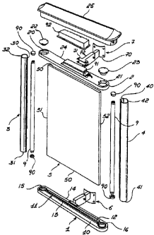
Figure 1 shows an exploded schematic axonometric view of a first cinbodime~ut
t0 of a device with a single lighted panel according to the present invention;
- Figure 2 shows a partially sectioned and exploded axonometric view of a
device
with three lighted panels according to the present invention applied to a road
lighting
post or the like;
- Figure 3 shows a partially sectioned and exploded schematic axonometric view
l5 of a variation of the device of Figure 2; and
- Figure 4 shows a schematic axonometric view of the device of Figures 2 and
3.
Description of the Illustrative Embodiments
With reference to a first embodiment of the invention, Figure 1 shows. in
20 exploded axonometric view, a device with a single lighted panel. The frame
of the
panel (as shown it has rectangular shape, but its shape could be different)
has, as its
horizontal sides, a lower elongated plate 1 and an upper elongated plate 2
and, as its
vertical sides, two uprights 3, 4 with hollow section. The elongated plates 1
and 2 and
the uprights 3, 4 delimit a panel 5. In this first embodiment the panel 5 is
constituted
25 by a plate of plastic material, for instance polycarbonate, or of different
material.
In order to hold the panel 5, the elongated plates 1 and 2 are provided, on
mutually opposite plates (Figure 1 shows only the face 1 U of the elongated
plate 1 ).
with housing seats 1 l, fitted with sealing gasket. The housing seat 11 of the
elongated
plate 1 presents two linear projections 12 and 13 destined to receive and hold
in their
CA 02335930 2000-12-21
WO 00/67244 PCT/IT99/00392
inter-space a lower edge 50 of the panel S.
The uprights 3, 4 have an open hollow profile section. The section is shown as
being circular, but it can also be polygonal. It presents and opening 30, 40
for the
insertion of lateral edges 51, 52 of the panel in the respective uprights 3,
4. Between
5 the panel 5 and the uprights 3 and 4, sealing gaskets (not shown herein) may
be
provided.
To form a frame, the lower elongated plate 1 is provided, in correspondence
with
the extremities of the panel housing seat 11, with a pair of equal receiving
cavities
1 S, 16, with section conforming to that of the lower extremities 31, 41 of
the uprights
3, 4. These extremities can be fitted in the cavities 15, 16 with the
interposition of a
seating gasket. The upper elongated plate 2 is similarly provided with a pair
of
through holes 20, 21 for the upper extremities 32, 42 of the uprights 3, 4.
The holes
20, 21 have their section conforming to that of the uprights 3, 4, but with
l,~reater
surface are, in order to allow their upwards extraction. The holes 20, 21 are
closed
~ 5 with respective closure stoppers 22, 23 fastened by screwing onto the
elongated plate
2. The upper elongated plate 2 is surmounted by a covering element 25 destined
to
serve as a protection and finish for the frame.
The lower and upper elongated plates 1 and 2 present, on their corresponding
flanks 14, 24, means 6, 7 for fastening to a road lighting post or the like 8
shown in
2o Figures 2 to 4. The fastening means 6, 7 are substantially identical and
therefore only
the upper ones, indicated with 7, shall be described hereafter. They are
constituted by
a bracket 70 for fastening to the post, by a bracket 71 for fastening to the
elongated
plate 2 of the frame and by a telescoping arm 72. The bracket 70 for anchoring
to the
post by means of screws is appropriately curved and integral to a first
segmuent of the
25 telescoping arm 72, whereas the bracket 71 for fastening to the frame by
means of
screws is integral with a second segment of the same ann. The two segments of
the
telescoping arm 72 are able mutually to slide and be locked together in a
conventional
manner once the desired distance of the frame from the post has been
determined.
The fastening means 6, 7 have been shown as individual and centrally
positioned.
CA 02335930 2000-12-21
WO 00/67244 PG"T/IT99/00392
6
Naturally, they can be double, as an alternative, with a different disposition
on the
lower and upper elongated plates.
According to this first embodiment, wherein the panel 5 is constituted by a
sheet
~f clear material bearing images and/or captions to be lighted, the uprights
3, 4 are
made of opaque material. Inside them at least two fluorescent lamps,
generically
indicated with the number 9, are housed on related end lamp holders
(generically
indicated with the number 90). The lamps 9 are destined to emit light only
through
the longitudinal openings 30, 4G of the uprights 3, 4 within the edges 51, 52
of the
panel ~ in the form of a plate.
l0 Conventionally, the lamps 9, through the respective lamp holders 9G, arc:
connected with a power supply circuit having, for instance, an electronic
starter 91,
situated on the upper elongated plate 2 and housed in a hermetic protective
box 92.
Advantageously, this power supply circuit is connected to a road lighting
line, the
sane that powers the lamp or lamps borne by the post and which is slaved to a
start
IS control regulated by a ambient light sensor (not shown in the drawings).
Conveniently, although not shown in the drawings, the plate that constitutes
the
panel S is machined to present a surface with micro-prisms for the diffusion
of the
light emitted therein by the fluorescent lamps.
In Figures from 2 to 4 the lighted panel device according to the invention is
20 shown in a configuration with three boards individually united, by means of
the
means for fastening to the post 8.
As shown in Figure 2, the images and.~or captions to be lighted are realised
on
a film. indicated as 53, able to be applied adhesively and removably onto the
surface
oriented towards the exterior of the plate. Alternatively, the plate of the
panel S is
25 treated with serigraphy or otherwise printed.
In a second embodiment of the invention, instead of being constituted by a
plate,
the panel 5 can be constituted by a lighted display of variable images and/or
captions,
indicated as 54 in Figure 2. This display can be constituted by a LED or
plasma panel
or by a panel of a different kind. Naturally, if the panel S is a lighted
display of these
CA 02335930 2000-12-21
WO 00/67244 PCT/IT99/00392
7
types, the uprights do not serve the purpose of containing the fluorescent
lamps, but
only that of supporting the panel. The display control means, not further
described,
are comprised in the related system for communicating with a remote station
(not
shown in the drawings j and are able to receive communication or notification
messages to be displayed on the panel. Similarly, the panel in the form of a
plate, and
means for controlling, powering, and lighting the lighted display, destined to
be
situated in proximity thereto, are positioned on an upper elongated plate 2
and housed
in a protective hermetically sealed box 92.
The display is connected to an electrical power supply line independent from
the
io road lighting line slaved to ambient light sensors. Alternatively, the
display can be
connected to the same road lighting network; in this case the control, power
supply,
and lighting means include a buffer battery (not shown herein).
As shown in Figure 3, the lighted panel device according to the invention, in
one
of its variations, comprises sensors, indicated generically with the number
93, for the
detection of polluting substances contained in the atmosphere. The sensors,
through
dedicated lines or radio transmission, send atmospheric pollution data to a
remote
unit which in turn could send warning messages to be displayed on a panel of
the
lighted panel device of the invention.
As an alternative to the configurations shown, though not one expressly shown
2o herein, the device according to the invention can be realised with only two
panels
individually applied to a lighting post or the like in opposite positions. The
configuration with the panels fastened in consecutive positions, the uprights
being
adjacent, is advantageous because it allows to view the same images from
multiple
directions.
The device with three lighted panels shown in Figures 2 through 4 presents a
covering element 26, shaped according to a configuration mith a substantially
triangular plan form and provided with a r.entral hole 27. The covering
element 2f~
can therefore comprise three integral moulded elements, generically indicated
with
the number 28, approached to the road lighting post or the like. The covering
element
CA 02335930 2000-12-21
WO 00/67244 PCT/IT99/00392
26 is destined to be set down and removably fastened jointly onto the
respective
upper elongated plates of the three boards.
It may be advantageous for at least a panel of the three boards to be
constituted
by a lighted display of variable images and/or captions, whilst the other two
can be
constituted by a panel in the form of lighted plate.
Naturally, the invention thus conceived can be subject to numerous
modifications
and variations, without thereby departing from the scope of the inventive
concept.