Note: Descriptions are shown in the official language in which they were submitted.
CA 02336071 2000-12-22
WO 99/66971 PCT/US99/14257
TITLE OF THE INVENTION
Method and Device for Applications of Selective Organ Cooling
BACKGROUND OF THE INVENTION
Field of the Invention - The present invention relates generally to the
modification and control of the temperature of a selected body organ. More
particularly, the invention relates to applications of selective organ cooling
which
advantageously- employ complementary techniques.
Background Information - Organs in the human body, such as the brain, kidney
and heart, are maintained at a constant temperature of approximately
37°C.
to Hypothermia can be clinically defined as a core body temperature of
35°C or less.
Hypothermia is sometimes characterized further according to its se~~erity. A
body core
temperature in the range of 33°C to 35°C is described as mild
hypothermia. A body
temperature of 28°C to 32°C is described as moderate
hypothermia. A body core
temperature in the range of 24°C to 28°C is described as severe
hypothermia.
~5 Hypothermia is uniquely effective in reducing brain injury caused by a
variety
of neurological insults and may eventually play an important role in emergency
brain
resuscitation. Experimental evidence has demonstrated that cerebral cooling
improves
outcome after global ischemia, focal ischemia, or traumatic brain injury. For
this
reason, hypothermia may be induced in order to reduce the effect of certain
bodily
2o injuries to the brain as well as other organs.
Cerebral hypothermia has traditionally been accomplished through whole body
cooling to create a condition of total body hypothermia in the range of
20°C to 30°C.
However, the use of total body hypothermia risks certain deleterious
systematic
vascular effects. For example, total body hypothermia may cause severe
derangement
25 of the cardio~~ascular system, including low cardiac output. elevated
systematic
resistance, and ventricular fibrillation. Other side effects include renal
failure,
disseminated intravascular coagulation, and electrolyte disturbances. in
addition to the
undesirable side effects, total body hypothermia is difficult to administer.
Catheters have been developed which are inserted into the bloodstream of the
3o patient in order to induce total body hypothermia. For example, U.S. Patent
No.
3,425,419 to Dato describes a method and apparatus of lowering and raising the
SUBSTITUTE SHEET ( rule 26 )
CA 02336071 2000-12-22
WO 99/66971 PCT/US99/14257
temperature of the human body. Dato induces moderate hypothermia in a patient
using
a metallic catheter. The metallic catheter has an inner passagevrav through
which a
fluid, such as water, can be circulated. The catheter is inserted through the
femoral
vein and then through the inferior vena cava as far as the right atrium and
the superior
vena cava. The Dato catheter has an elongated cylindrical shape and is
constructed
from stainless steel. By way of example, Dato suggests the use of a catheter
approximately 70 cm in length and approximately 6 mm in diameter. However, use
of
the Dato device implicates the negative effects of total body hypothermia
described
above.
Due to the problems associated with total body hypothermia, attempts have
been made to provide more selective cooling. For example. cooling helmets or
headgear have been used in an attempt to cool only the head rather than the
patient's
entire body. However, such methods rely on conductive heat transfer through
the skull
and into the brain. One drawback of using conductive heat transfer is that the
process
of reducing the temperature of the brain is prolonged. Also, it is difficult
to precisely
control the temperature of the brain when using conduction due to the
temperature
gradient that must be established externally in order to sufficiently lower
the internal
temperature. In addition, when using conduction to cool the brain, the face of
the
patient is also subjected to severe hypothermia, increasing discomfort and the
likelihood of negative side effects. It is known that profound cooling of the
face can
cause similar cardiovascular side effects as total body cooling. From a
practical
standpoint, such devices are cumbersome and may make continued treatment of
the
patient difficult or impossible.
Selected organ hypothermia has been accomplished using extracorporeal
perfusion, as detailed by Arthur E. Schwartz, M.D. et al., in Isolated
Cerebral
Hypothermia by Single Carotid Artery Perfusion of Extracorporeally Cooled
Blood in
Baboons, which appeared in Vol. 39, No. 3. NEUROSURGERY 577 (September, 1996).
In
this study, blood was continually withdrawn from baboons through the femoral
artery.
The blood was cooled by a water bath and then infused through a common carotid
3o artery with its external branches occluded. Using this method, normal heart
rhythm,
systemic arterial blood pressure and arterial blood gas values were maintained
during
the hypothermia. This study showed that the brain could be selectively cooled
to
temperatures of 20° C without reducing the temperature of the entire
body. However,
SUBSTITUTE SHEET ( ruie 26 )
CA 02336071 2000-12-22
WO 99/66971 PCT/US99/14257
external circulation of blood is not a practical approach for treating humans
because the
risk of infection, need for anticoagulation, and risk of bleeding is too
great. Further,
this method requires cannulation of two vessels making it more cumbersome to
perform
particularly in emergency settings. Even more, percutaneous cannulation of the
carotid
artery is difficult and potentially fatal due to the associated arterial wall
trauma.
Finally, this method would be ineffective to cool other organs, such as the
kidneys,
because the feeding arteries cannot be directly cannulated percutaneously.
Selective organ hypothermia has also been attempted by perfusion of a cold
solution such as saline or perflourocarbons. This process is commonly used to
protect
1 o the heart during heart surgery and is referred to as cardioplegia.
Perfusion of a cold
solution has a number of drawbacks, including a limited time of administration
due to
excessive volume accumulation. cost, and inconvenience of maintaining the
perfusate
and lack of effectiveness due to the temperature dilution from the blood.
Temperature
dilution by the blood is a particular problem in high blood flow organs such
as the
t5 brain.
BRIEF SUMMARY OF THE INVENTION
The invention provides a practical method and apparatus which modifies and
controls the temperature of a selected organ and which may be used in
combination
?o with many complementary therapeutic techniques.
In one aspect, the invention is directed towards a device for heating or
cooling a
surrounding fluid in a feeding vessel. The device includes a catheter assembly
capable
of insertion to a selected feeding vessel in the vascular system of a patient.
The
assembly includes a heat transfer element at a distal end of the catheter
assembly, the
35 heat transfer element having a plurality of exterior surface irregularities
shaped and
arranged to create turbulence in a surrounding fluid, the surface
irregularities having a
depth at least equal to the boundary layer thickness of flow of the
surrounding fluid in
the feeding vessel. The surrounding fluid may be, e.g., blood in a blood
vessel,
working fluid within the heat transfer element, etc., and combinations
thereof. The
3o assembly further includes a supply catheter to deliver a working fluid to
an interior of
the heat transfer element and a return catheter to return a working fluid from
the
interior of the heat transfer element. A drug delivery catheter is also
provided and runs
substantially parallel to the axis of the catheter assembly.
SUBSTITUTE SHEET ( rule 26 )
CA 02336071 2000-12-22
27-06-2000 US 009914257
. ~ ~ , .. ...
.. .. - , - . ~.. .. .. ..
. . s ~ ~~ . w v
~' . ... . ~ . .
v. .
~ . ~ . ~ ~ v .
_ ~ . . . . ~ ~ .
~ . ..~.
~- ~ .. f~
WO 99166971 ~PCT/US99/I4257
. ~- ~ w ~ w Implementations of the invention may include one, or more of the
following.
Turbulence may be created around a plurality of surface irregularities on the
heat
transfer element at a distance from the heat transfer element greater than the
boundary
Iayer thiclmess of flow in the feeding vessel, thereby creating turbulence
throughout a
free stream of blood flow in the feeding vessel: The surface irregularities on
the heat
transfer element may include a plurality of segments of. helical ridges and
grooves
having alternating directions of helical rotation; and turbulence is created
by
establishing repetitively alternating directions of helical .blood flow with
the alternating
helical rotations of the ridges and groves. The liquid may be a warm enzyme
solution,
I o and may be selected from the group consisting of tPA, streptokinase,
urokinase, pro-
urokinase, and combinations thereof. The liquid may be delivered to the volume
in a
Longitudinal or transverse direction with respect to the. axis of the catheter
assembly.
The liquid may be delivered to the volume proximal or distal of the distal tip
of the
catheter assembly. If the volume of blood includes a blood clo~during the
delivering
~s of the liquid the distal tip of the catheter assembly may. be. disposed
substantially near,
adjacent, or embedded in the blood clot. Air aiay be delivered to at least ane
seated
luiaet~ within the return catheter to cause the sealed lumen to enlarge. . The
air rnay
further be delivered in a pulsatile fashion to rep~adly enlarge and contract
the sealed
lumen, thereby to create additional_turbultnce, e.g., to enfiance heat
transfer.
A further aspect of~.the catheter assembly involves
a method for selectively controlling the temperature of
a selected volume of blood in a patient. The method
includes introducing the catheter assembly into a blood
vessel~feeding a selected volume of blood in a patient;
delivering a working fluid through a supply catheter in
the catheter assembly and returning the working fluid
through a return catheter in the catheter assembly;
transferring heat between a heat transfer element forming ,
a distal end of the catheter assembly and the volume of
blood in the feeding vessel; and delivering a liquid,
which may be a warm enzyme solution, through a drug
delivery catheter to the volume of blood in the feeding
vessel. The warm enzyme solution may be selected from the
following group consisting of tPA, streptokinase, uro-
kinase, pro-urokinase, and combinations thereof.
The method may further include creating turbulence
around a plurality of surface irregularities on the heat
transfer element at a distance from the heat transfer
element greater than the boundary layer thickness of flow
in the feeding vessel, thereby creating turbulence
throughout a free stream of blood in the feeding vessel.
These
AMENDED SHEET
CA 02336071 2000-12-22
27-06-2000 US 009914257
. .
.. ., ... . , .. .. .. ..
... ; ~~ . ..
. ... . v . .
. : .. . . -_,
- WO 99/66971 ~ ~ .... ~ p~~jS~14257~~ ~ ~~~
Implementations of the invention may include one or more of the following.
The drug delivery catheter may be disposed substantially coaxially with
respect to the
supply catheter. The drug delivery catheter may include as outlet at a distal
end
thereof, the distal end of the drug delivery catheter distal of a distal end
of the return or
S supply catheters. The drug delivery catheter may be disposed within one of
the return
catheter or the supply catheter or both, and may include an outlet transverse
or parallel
to the axis of the catheter assembly. The surface irregularities may include a
helical
ridge and a helical groove formed on each of successive heat transfer
segments; and the
helical ridge on each heat transfer segment may have an opposite helical twist
to the
1 o helical ridges on adjacent heat transfer segments. At least one sealed
lumen within one
of the return catheter or the supply catheter or both may be provided. the
sealed lumen
in pressure communication with a supply of air to inflate the sealed lumen.
The return
catheter may be coaxial with the supply catheter, and the return catheter have
a larger
or smaller radius than the supply catheter, depending on the requi~ezuerits of
the user.
t5 In another aspect, the invention is directed to a device for heating or
cooling a
surrounding fluid in a feeding vessel. Ia this aspect, the heat traasfer
element has a
distal end which defines an orifice. A supply catheter deliver a working fluid
to an
interior of the heat transfer element, the supply catheter having a working
fluid catheter
disposed therein .and further having disposed therein a drug delivery catheter
running
2o substantially parallel to the axis of the supply catheter. The working
fluid catheter has
defined thereon a number of outlets to communicate the working fluid from the
interior
of the supply catheter to a volume defined by the exterior of the supply
catheter and the
interior of the heat transfer element. The device further includes a return
catheter to
return the working fluid from the interior of the heat transfer element.
25 In yet another aspect, the catheter assembly can
selectively control the temperature of a selected volume
of blood in a patient. A method directed to this aspect
includes introducing the catheter assembly into a' blood
vessel feeding a selected volume
of blood in a patient, and delivering a working fluid through a supply
catheter in the
catheter assembly and returning the working fluid through a return catheter in
the
3o catheter assembly. Heat is transferred between a heat transfer element
forming a distal
end of the catheter assembly and the volume of blood in the feeding vessel. A
liquid is
delivered through a drug delivery catheter to the volume of blood in the
feeding vessel.
AMENDED SHEET
CA 02336071 2000-12-22
27-06-2000 US 009914257
.
.. .. .. .. _. .. ..
. . . ~ ; ~ .. , ,....
. r ... . v r
- 1 . . .. . . . r .
- ~ . ~ v ..v _ . ..~ ~ ~ ~
-~ ~~ ~ w w.
WO 99/66971 PCT/US99/14257
surface irregularities on the heat transfer element may
comprise a plurality of segments of helical ridges and grooves
having alternating directions of helical rotation; and
turbulence is created by establishing repetitively alternating
directions of helical blood flow with the alternating helical
rotations of the ridges and grooves.
The method may further include delivering air in a
pulsatile fashion to the at least one sealed lumen within he
return catheter to cause the sealed Lumen to repeatedly enlarge
and contract.
Also, the method may further include delivering the liquid
to the volume in a longitudinal or transverse direction with
respect to the axis of the catheter assembly or delivering the
liquid to the volume proximal or distal of the distal tip of
the catheter assembly.
If the volume of blood includes a blood clot, the distal
tip of the catheter assembly may be substantially near,
adjacent, or embedded in the blood clot.
Advantages of the invention include the following. The
device may be placed in an artery without traumatizing the
arterial wall and with damaging the device itself. The device
may be placed in an artery simply and by a variety of
practitioners such as cardiologists or neurosurgeons. The
device allows the complementary performance of
6
AMENDED SHEET
CA 02336071 2000-12-22
27-06-2000 US 009914257
~ ~ .. ....
~. .~ ~ ~ -~ ~~ v~ W
~ . ~ ~ v ~ ~~. ~ . . ~
1 1 ~ ~ 1 . ~ ~ ~ ~ 1
1 .
WO 99/66971 PCT/US99/14257
simultaneous procedures along with brain cooling, these
procedures including angiography, stenotic lesion stenting, and
drug delivery.
A still further aspect of the the catheter asssembly
involves a method for selectively controlling the temperature
of a selected organ of a patient for performance of a specified
application. The method includes introducing a guide catheter
into a blood vessel; providing a supply tube having a heat
transfer element attached to a distal end thereof, the heat
transfer element having a plurality of exterior surface
irregularities, the surface irregularities having a depth
greater than the boundary layer thickness of flow in the
feeding artery of the selected organ; inserting the supply tube
and heat transfer element through the guide catheter to place
the heat transfer element in the feeding artery of the selected
organ; creating turbulence around the surface irregularities at
a distance from the heat transfer element greater than the
boundary layer thickness of flow in the feeding artery, thereby
creating turbulence throughout the blood flow in the feeding
artery; circulating fluid into the heat transfer element via
the supply tube; circulating fluid out of the heat transfer
element via the guide catheter; and transferring heat between
the heat transfer element and the blood in the feeding artery
to selectively control the temperature of the selected organ.
The method may further include inducing blood turbulence
in greater than 20% of the period of the cardiac cycle within
the carotid artery.
The surface irregularities on the heat transfer element
may comprise a plurality of segments of helical ridges and
grooves having alternating directions of helical rotation; and
turbulence is created by establishing repetitively alternating
directions of helical blood flow with the alternating helical
rotations of the ridges and grooves.
A further aspect of the catheter assembly involves a
method for selective thrombolysis by selective vessel
hypothermia. The method includes introducing a guide catheter
into a thrombosed blood vessel; delivering a thrombolytic drug
such as streptokinase to the blood by flowing the thrombolytic
drug into the guide catheter; introducing a supply tube having
a heat transfer element at a distal end thereof into the
thrombosed blood vessel through the guide catheter; cooling the
heat transfer element by flowing a working fluid through the
heat transfer element, the return path for the working fluid
being the guide catheter; and
AMENDED SHEET
i
__ ~.__w___.__ .
CA 02336071 2000-12-22
27-06-2000 US 009914257
:. .. ,-~~ ...; _. .. .. ..
. ..
' ; ~~ ,~ ~ ~ ... i i s
. , ~ . . . ~ ~
. ~ ~.'r ~ ~ . . . . . r .
.. .. . w ..
WO 99/66971 PCT/US99/14257
cooling the blood by flowing the blood past the heat transfer
element, such that the blood is cooled to a prespecified
S temperature range, preferably between 30°C and 32°C for
streptokinase.
The thrombolytic drug may also be chosen from the group
consisting of tPA, urokinase, streptokinase, precursors of
urokinase, and combinations thereof.
l0 If the chosen thrombolytic drug is urokinase, the
prespecified temperature range should be below about 28°C.
If the chosen thrombolytic drug is a precursor, to
urokinase, the prespecified temperature range should be below
about 28°C.
15 Another aspect of the catheter assembly involves a method
for selective thrombolysis by selective vessel hyperthermia.
The method includes a guide catheter into a thrombosed blood
vessel; delivering a thrombolytic drug to the blood by flowing
the thrombolytic drug into the guide catheter; introducing a
20 supply tube having a heat transfer element at a distal end
thereof into the thrombosed blood vessel through the guide
catheter; heating the heat transfer element by flowing a
working fluid through the heat transfer element, the return
path for the working fluid being the guide catheter; and
25 heating the blood by flowing the blood past the heat transfer
element, such that the blood is heated to a prespecified
temperature range.
The drug may be chosen from the group consisting of tPA,
urokinase, streptokinase, precursors of urokinase, and
30 combinations thereof.
If the chosen drug is tPA, the prespecified temperature
range should be between about 37°C and 40°C.
A further aspect of the catheter assembly involves a
method for performing angiography during selective vessel
35 hypothermia. The method includes introducing a guide catheter
into a blood vessel; delivering a radioopaque fluid to the
blood by flowing the radioopaque fluid into the guide catheter;
introducing a supply tube having a heat transfer element at a
distal end thereof into the blood vessel through the guide
40 catheter; cooling the heat transfer element by flowing a
working fluid through the heat transfer
a5
8
AMENDED SHEET
CA 02336071 2000-12-22
27-06-2000 US 009914257
:. ~ .. ...; .. ..
. .': ' ; . .. ,
.. , : ,
~ ~ .' ~ ,
.. _... ~ . .. . .
WO 99/66971 PCT/US99/I4257 ~ ~~
element, the return path for the working fluid being the guide catheter, and
cooling the
blood by flowing the blood past the heat transfer element. such that the blood
is cooled
to a prespecifred temperature range.
A still further aspect of the catheter assembly involves
a method for performing stenting
of a stenotic lesion during selective vessel hypothermia. The method includes
introducing a e~uide catheter into a blood vessel; introducing a guide wire
through the
guide catheter and across a stenotic lesion; delivering a balloon catheter
loaded with a
stent via the guide wire; positioning the stent across the lesion; expanding
the balloon
with contrast; deploying the stent; introducing a supply tube having a heat
transfer
element at a distal end thereof into the blood vessel through the guide
catheter; cooling
the heat transfer element by flowing a working fluid through the heat transfer
element,
the return path for the working fluid being the guide catheter, and cooling
the blood by
flowing the blood past the heax transfer element, such that the blood is
cooled to a
prespecified temperature range. ,
-- ys --w~w --- Art--additional--- aspect of-- t-fire ca-t-he-ter -assembly-- -
~--
involves a method for selectivel
controlling the temperature of a selected organ ofya patient for perfonnance
of a
specified application. The method includes introducing a return catheter into
a blood
vessel having a heat transfer element attached to a distal end thereof, the
heat transfer
element having a plurality of exterior surface irregularities, the surface
irregularities
2o having a depth greater than the boundary Layer thickness of flow in the
feeding artery of
the selected oigan, the heat transfer element having an outlet at a distal end
thereof;
insetting a working fluid catheter into the return catheter and heat transfer
element such
that the working fluid catheter plugs the outlet of the heat transfer element;
creating
turbulence around the surface irregularities at a distance from the heat
transfer element
25 greater than the boundary layer thickness of flow in the feeding artery,
thereby creating
turbulence throughout the blood flow in the feeding artery; circulating
fluid,into the
heat transfer element via the working fluid catheter; circulating fluid out of
the heat
transfer element via the return catheter; and transferring heat between the
heat transfer
element and the blood in the feeding artery to selectively control the
temperature of the
3o selected organ.
The method may further include. -
. removing the working fluid catheter from the return catheter and the heat
transfer element: inserting a delivery catheter into the return catheter and
the heat
AMENDED SHEET
CA 02336071 2000-12-22
27-06-2000 US 009914257
.. .. ~~ ...: .. .. ..
. . ' : . ~ -~ . ,~...
. . ,- , : . .-. . . .
W0~99/66971 ~ : .~... : . ~tE'f1U~99~1d?,ST' ~.
transfer element, the delivery catheter having a delivery outlet at a distal
end thereof;
and delivering a drub via the delivery catheter.
In addition, the surface irregularities on the heat
transfer element may comprise a plurality of segments of
helical w ~ ~ -
s ridges and grooves having alternating directions of helical rotation: and
turbulence is
created by establishing repetitively alternating directions of helical blood
flow with the
alternating helical rotations of the ridges and grooves.
A further-aspect of the catheter assembly- involves a method
for selectively controlling
the temperature of a selected organ of a patieat for performance of a
specified
t o application. The method includes introducing a return catheter into a
blood vessel
having a heat transfer element attached to a distal end thereof, the heat
transfer element
having a plurality of exterior surface irregularities, the surface
irregularities having a
depth greater than the boundary Iayer thickness of flow in the feeding artery
of the
selected organ, the heat transfer element having an outlet at a distal end
thereof;
15 inserting a delivery / working fluid catheter into the return catheter and
heat transfer
element such that the delivery / working fluid catheter plugs the outlet of
the heat
transfer element in a first condition and an inflatable balloon coupled to a
distal end of
the delivery / working fluid catheter plugs the outlet of the heat transfer
element in a
second condition, the delivery / working fluid catheter. having a delivery
outlet at the
2o distal end thereof and at least one working fluid outlets ~at a distance
upstream of the
distal end; creating turbulence around the surface irregularities at a
distance from the
heat transfer element greater than the boundary layer thickness of flow in the
feeding
artery, thereby creating turbulence throughout the blood flow in the feeding
artery; in
the first condition, circulating fluid into the heat transfer element ~za the
working fluid
3s catheter, circulating fluid out of the heat transfer element via the return
catheter; and
transferring heat between the heat transfer element and the blood in the
feeding artery
to selectively control the temperature of the selected organ; and in the
second condition,
delivering a drug to the blood via the delivery outlet in the first condition.
The novel features of this invention. as well as the invention itself, will be
best
3o understood from the attached drawings, taken along with the follow ng
description. in
which similar reference characters refer to similar parts, and in which:
AMENDED SHEET
CA 02336071 2000-12-22
WO 99/66971 PCT/US99114257
BRIEF DESCRIPTION OF THE SEVERAL VIEWS OF THE DRAWINGS
Figure 1 is a front view of a first embodiment of a turbulence inducing heat
transfer element according to the principles of the invention within an
artery;
Figure 2 is a more detailed front view of the heat transfer element of Figure
1;
Figure 3 is a front sectional view of the heat transfer element of Figure 1;
Figure 4 is a transverse sectional view of the heat transfer element of Figure
1;
Figure ~ is a front perspective view of the heat transfer element of Figure 1
in
use within a partially broken away blood vessel;
Figure 6 is a partially broken away front perspective view of a second
1o embodiment of a turbulence inducing heat transfer element according to the
principles
of the invention;
Figure 7 is a transverse sectional view of the heat transfer element of Figure
6;
Figure 8 is a schematic representation of the invention being used to cool the
brain of a patient;
15 Figure 9 is a front sectional view of a guide catheter according to an
embodiment of the invention which may be employed for applications of the heat
transfer element according to the principles of the invention;
Figure 10 is a front sectional view of a third embodiment of a catheter
employing a heat transfer element according to the principles of the invention
further
2o employing a return tube / guide catheter;
Figure 11 is a front sectional view of a fourth embodiment of a catheter
employing a heat transfer element according to the principles of the invention
further
employing a delivery catheter;
Figure 12 is a front sectional view of the fourth embodiment of Figure 11
35 further employing a working fluid catheter;
Figure I3 is a front sectional view of a fifth embodiment of a catheter
employing a heat transfer element according to the principles of the invention
further
employing a guide wire;
Figure 14 is a front sectional view of a sixth embodiment of a catheter
3o employing a heat transfer element according to the principles of the
invention further
employing a delivery / working fluid catheter with a balloon attachment;
Figure 15 is a second front sectional view of the sixth embodiment of Figure
14
shown with the balloon attachment occluding an opening in the heat transfer
element;
SUBSTITUTE SHEET ( rule 26 )
CA 02336071 2000-12-22
WO 99/66971 PCT/US99/14257
Figure 16 is a front sectional view of a seventh embodiment of a catheter
employing a heat transfer element according to the principles of the invention
further
employing a delivery lumen;
Figure 17 is a front sectional view of an eighth embodiment of a catheter
employing a heat transfer element according to the principles of the invention
further
employing a delivery lumen, this delivery lumen non-coaxial with the central
body of
the catheter;
Figure I 8 is a front sectional view of a ninth embodiment of a catheter
employing a heat transfer element according to the principles of the invention
further
to employing a delivery lumen, this delivery lumen non-coaxial with the
central body of
the catheter;
Figure 19 is a front sectional view of a tenth embodiment of a catheter
employing a heat transfer element according to the principles of the invention
further
employing multiple lumens;
15 Figure 20 is a cross-sectional view of the tenth embodiment of Figure 19,
taken
along lines 20-20 of Figure 19; and
Figure 21 is a front sectional view of an eleventh embodiment of a catheter
employing a heat transfer element according to the principles of the
invention.
2o DETAILED DESCRIPTION OF THE INVENTION
The temperature of a selected organ may be intravascularly regulated by a heat
transfer element placed in the organ's feeding artery to absorb or deliver
heat to or from
the blood flowing into the organ. While the method is described with respect
to blood
flow into an organ, it is understood that heat transfer within a volume of
tissue is
25 analogous. In the latter case, heat transfer is predominantly by
conduction.
The heat transfer may cause either a cooling or a heating of the selected
organ.
A heat transfer element that selectively alters the temperature of an organ
should be
capable of providing the necessary heat transfer rate to produce the desired
cooling or
heating effect within the organ to achieve a desired temperature.
3o The heat transfer element should be small and flexible enough to fit within
the
feeding artery while still allowing a sufficient blood flow to reach the organ
in order to
avoid ischemic organ damage. Feeding arteries, like the carotid artery, branch
off the
aorta at various levels. Subsidiary arteries continue to branch off these
initial branches.
12
SUBSTITUTE SHEET ( rule 26 )
... _.~._.
CA 02336071 2000-12-22
WO 99/66971 PCT/US99/14257
For example, the internal carotid artery branches off the common carotid
artery near the
angle of the jaw. The heat transfer element is typically inserted into a
peripheral artery,
such as the femoral artery, using a guide catheter or guide wire, and accesses
a feeding
artery by initially passing though a series of one or more of these branches.
Thus, the
flexibility and size, e.g., the diameter, of the heat transfer element are
important
characteristics. This flexibility is achieved as is described in more detail
below.
These points are illustrated using brain cooling as an example. The common
carotid artery supplies blood to the head and brain. The internal carotid
artery branches
off the common carotid artery to supply blood to the anterior cerebrum. The
heat
to transfer element may be placed into the common carotid artery or into both
the
common carotid artery and the internal carotid artery.
The benefits of hypothermia described above are achieved when the
temperature of the blood flowing to the brain is reduced to between
30°C and 32°C. A
typical brain has a blood flow rate through each carotid artery (right and
left) of
15 approximately 250-375 cubic centimeters per minute (cc/min). With this flow
rate,
calculations show that the heat transfer element should absorb approximately
75-175
watts of heat when placed in one of the carotid arteries to induce the desired
cooling
effect. Smaller organs may have less blood flow in their respective supply
arteries and
may require less heat transfer, such as about 25 watts.
2o The method employs conductive and convective heat transfers. Once the
materials for the device and a working fluid are chosen, the conductive heat
transfers
are solely dependent on the temperature gradients. Convective heat transfers,
by
contrast, also rely on the movement of fluid to transfer heat. Forced
convection results
when the heat transfer surface is in contact with a fluid whose motion is
induced (or
25 forced) by a pressure gradient, area variation, or other such force. In the
case of arterial
flow, the beating heart provides an oscillatory pressure gradient to force the
motion of
the blood in contact with the heat transfer surface. One of the aspects of the
device uses
turbulence to enhance this forced convective heat transfer.
The rate of convective heat transfer Q is proportional to the product of S ,
the
3o area of the heat transfer element in direct contact with the fluid, DT = Tb
- T$ , the
temperature differential between the surface temperature T, of the heat
transfer
element and the free stream blood temperature Tb, and h~ , the average
convection heat
13
SUBSTITUTE SHEET ( rule 2b )
CA 02336071 2000-12-22
WO 99/66971 PCT/US99/14257
transfer coefficient over the heat transfer area. h~ is sometimes called the
"surface
coefficient of heat transfer" or the "convection heat transfer coefficient".
The magnitude of the heat transfer rate Q to or from the fluid flow can be
increased through manipulation of the above three parameters. Practical
constraints
limit the value of these parameters and how much they can be manipulated. For
example, the internal diameter of the common carotid artery ranges from 6 to 8
mm.
Thus, the heat transfer element residing therein may not be much larger than 4
mm in
diameter to avoid occluding the vessel. The length of the heat transfer
element should
also be limited. For placement within the internal and common carotid artery,
the
to length of the heat transfer element is limited to about 10 cm. This
estimate is based on
the length of the common carotid artery, which ranges from 8 to 12 cm.
Consequently, the value of the surface area S is limited by the physical
constraints imposed by the size of the artery into which the device is placed.
Surface
features, such as fins, can be used to increase the surface area of the heat
transfer
element, however, these features alone cannot provide enough surface area
enhancement to meet the required heat transfer rate to effectively cool the
brain.
One may also attempt to vary the magnitude of the heat transfer rate by
varying
~T. The value of DT =Tb -TS can be varied by varying the surface temperature
Ts
of the heat transfer element. The allowable surface temperature of the heat
transfer
2o element is limited by the characteristics of blood. The blood temperature
is fixed at
about 37°C, and blood freezes at approximately 0°C. When the
blood approaches
freezing, ice emboli may form in the blood which may lodge downstream, causing
serious ischemic injury. Furthermore, reducing the temperature of the blood
also
increases its viscosity which results in a small decrease in the value of h~ .
Increased
viscosity of the blood may further result in an increase in the pressure drop
within the
artery, thus compromising the flow of blood to the brain. Given the above
constraints,
it is advantageous to limit the surface temperature of the heat transfer
element to
approximately 1 °C - 5°C, thus resulting in a maximum
temperature differential
between the blood stream and the heat transfer element of approximately
32°C - 36°C.
3o One may also attempt to vary the magnitude of the heat transfer rate by
varying
h~ . Fewer constraints are imposed on the value of the convection heat
transfer
coefficient h~ . The mechanisms by which the value of h~ may be increased are
14
SUBSTITUTE SHEET ( rule 26 )
CA 02336071 2000-12-22
WO 99/66971 PCT/US99/14257
complex. However. one way to increase h~ for a fixed mean value of the
velocity is to
increase the level of turbulent kinetic energy in the fluid flow.
The heat transfer rate Q°°-~°W in the absence of fluid
flow is proportional to DT,
the temperature differential between the surface temperature T s of the heat
transfer
element and the free stream blood temperature Tb times k, the diffusion
constant, and
is inversely proportion to S , the thickness of the boundary layer.
The magnitude of the enhancement in heat transfer by fluid flow can be
estimated by taking the ratio of the heat transfer rate with fluid flow to the
heat transfer
rate in the absence of fluid flow N = Q~°W / Q~°-t~°W =
h~ / (k/8). This ratio is called the
to Nusselt number ("Nu"). For convective heat transfer between blood and the
surface of
the heat transfer element, Nusselt numbers of 50-80 have been found to be
appropriate
for selective cooling applications of various organs in the human body.
Nusselt
numbers are generally dependent on several other numbers: the Reynolds number,
the
Womersley number, and the Prandtl number.
Stirring-type mechanisms, which abruptly change the direction of velocity
vectors, may be utilized to induce turbulent kinetic energy and increase the
heat transfer
rate. The level of turbulence so created is characterized by the turbulence
intensity 8.
Turbulence intensity 9 is defined as the root mean square of the fluctuating
velocity
divided by the mean velocity. Such mechanisms can create high levels of
turbulence
z0 intensity in the free stream, thereby increasing the heat transfer rate.
This turbulence
intensity should ideally be sustained for a significant portion of the cardiac
cycle, and
should ideally be created throughout the free stream and not just in the
boundary layer.
Turbulence does occur for a short period in the cardiac cycle anyway. In
particular, the blood flow is turbulent during a small portion of the
descending systolic
flow. This portion is less than 20% of the period of the cardiac cycle. If a
heat transfer
element is placed co-axially inside the artery, the heat transfer rate will be
enhanced
during this short interval. For typical of these fluctuations, the turbulence
intensity is at
least 0.05. In other words, the instantaneous velocity fluctuations deviate
from the
mean velocity by at least 5%. In some embodiments, lower fluctuations may be
3o employed, such as 3% or even 2%. Although ideally turbulence is created
throughout
the entire period of the cardiac cycle. the benefits of turbulence are
obtained if the
SUBSTITUTE SHEET ( rule 26 )
CA 02336071 2000-12-22
WO 99/66971 PCT/US99/14257
turbulence is sustained for 75%, 50% or even as low as 30% or 20% of the
cardiac
cycle.
One type of turbulence-inducing heat transfer element which may be
advantageously employed is a heat transfer element made of a high thermal
conductivity material, such as metal. The use of a high thermal conductivity
material
increases the heat transfer rate for a given temperature differential between
the coolant
within the heat transfer element and the blood. This facilitates the use of a
higher
temperature coolant within the heat transfer element, allowing safer coolants,
such as
water, to be used. Highly thermally conductive materials, such as metals, tend
to be
1 o rigid. In that application, bellows provided a high degree of articulation
that
compensated for the intrinsic stiffness of the metal. In another application,
the bellows
are replaced with a straight metal tube having a predetermined thickness to
allow
flexibility via bending of the metal. Alternatively, the bellows may be
replaced with a
polymer tube, e.g., a latex rubber tube, a plastic tube, or a flexible plastic
corrugated
tube.
The device size may be minimized, e.g., less than 4 mm, to prevent blockage of
the blood flowing in the artery. The design of the heat transfer element
should facilitate
flexibility in an inherently inflexible material.
To create the desired level of turbulence intensity in the blood free stream
2o during the whole cardiac cycle, one embodiment of the device uses a modular
design.
This design creates helical blood flow and produces a high level of turbulence
in the
free stream by periodically forcing abrupt changes in the direction of the
helical blood
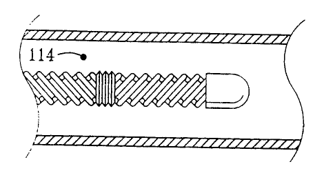
flow. Figure 1 is a perspective view of such a turbulence inducing heat
transfer
element within an artery. Turbulent flow would be found at point 114, in the
free
stream area. The abrupt changes in flow direction are achieved through the use
of a
series of two or more heat transfer segments, each comprised of one or more
helical
ridges. To affect the free stream, the depth of the helical ridge is larger
than the
thickness of the boundary layer which would develop if the heat transfer
element had a
smooth cylindrical surface.
3o The use of periodic abrupt changes in the helical direction of the blood
flow in
order to induce strong free stream turbulence may be illustrated with
reference to a
common clothes washing machine. The rotor of a washing machine spins initially
in
one direction causing laminar flow. When the rotor abruptly reverses
direction,
16
SUBSTITUTE SHEET ( rule 26 )
__~. ~..
CA 02336071 2000-12-22
WO 99/66971 PCT/US99/14257
significant turbulent kinetic energy is created within the entire wash basin
as the
changing currents cause random turbulent motion within the clothes-water
slurry.
Figure ? is an elevation view of one embodiment of a heat transfer element 14.
The heat transfer element I4 is comprised of a series of elongated.
articulated segments
or modules 20. 22, 24. Three such segments are shown in this embodiment, but
two or
more such segments could be used. As seen in Figure 2, a first elongated heat
transfer
segment 20 is located at the proximal end of the heat transfer element I4. A
turbulence-inducing exterior surface of the segment 20 comprises four parallel
helical
ridges 28 with four parallel helical grooves 26 therebetween. One, two, three,
or more
1o parallel helical ridges 28 could also be used. In this embodiment, the
helical ridges 28
and the helical grooves 26 of the heat transfer segment 20 have a left hand
twist,
referred to herein as a counter-clockwise spiral or helical rotation, as they
proceed
toward the distal end of the heat transfer segment 20.
The first heat transfer segment 20 is coupled to a second elongated heat
transfer
segment 22 by a first tube section 25, which provides flexibility. The second
heat
transfer segment 22 comprises one or more helical ridges 32 with one or more
helical
grooves 30 therebetween. The ridges 32 and grooves 30 have a right hand, or
clockwise, twist as they proceed toward the distal end of the heat transfer
segment 22.
The second heat transfer segment 22 is coupled to a third elongated heat
transfer
2o segment 24 by a second tube section 27. The third heat transfer segn: _nt
24 comprises
one or more helical ridges 36 with one or more helical grooves 34
therebetween. The
helical ridge 36 and the helical groove 34 have a left hand, or counter-
clockwise, twist
as they proceed toward the distal end of the heat transfer segment 24. Thus,
successive
heat transfer segments 20, 22, 24 of the heat transfer element 14 alternate
between
having clockv~ise and counterclockwise helical twists. The actual left or
right hand
twist of any particular segment is immaterial, as long as adjacent segments
have
opposite helical twist.
In addition, the rounded contours of the ridges 28, 32, 36 also allow the heat
transfer element 14 to maintain a relatively atraumatic profile, thereby
minimizing the
3o possibility of damage to the blood vessel wall. A heat transfer element may
be
comprised of I<co, three. or more heat transfer segments.
The tube sections 25, 27 are formed from seamless and nonporous materials,
such as metal. and therefore are impermeable to gas, which can be particularly
SUBSTITUTE SHEET ( rule 26 )
CA 02336071 2000-12-22
WO 99/66971 PCT/US99/14257
important, depending on the type of working fluid that is cycled through the
heat
transfer element 14. The structure of the tube sections 25, 27 allows them to
bend,
extend and compress, which increases the flexibility of the heat transfer
element 14 so
that it is more readily able to navigate through blood vessels. The tube
sections 25, 27
are also able to tolerate cryogenic temperatures without a loss of
performance. The
tube sections 25, 27 may have a predetermined thickness of their walls, such
as
between about 0.5 and 0.8 mils. The predetermined thickness is to a certain
extent
dependent on the diameter of the overall tube. Thicknesses of 0.~ to 0.8 mils
may be
appropriate especially for a tubal diameter of about 4 mm. For smaller
diameters, such
1 o as about 3.3 mm, larger thicknesses may be employed for higher strength.
In another
embodiment. tube sections 25, 27 may be formed from a polymer material such as
rubber, e.g., latex rubber.
The exterior surfaces of the heat transfer element 14 can be made from metal
except in flexible joint embodiments where the surface may be comprised of a
polymer
material. The metal may be a very high thermal conductivity material such as
nickel,
thereby facilitating efficient heat transfer. Alternatively, other metals such
as stainless
steel, titanium, aluminum, silver, copper and the like, can be used. with or
without an
appropriate coating or treatment to enhance biocompatibility or inhibit clot
formation.
Suitable biocompatible coatings include, e.g., gold, platinum or polymer
paralyene.
The heat transfer element 14 may be manufactured by plating a thin layer of
metal on a
mandrel that has the appropriate pattern. In this way, the heat transfer
element 14 may
be manufactured inexpensively in large quantities, which is an important
feature in a
disposable medical device.
Because the heat transfer element 14 may dwell within the blood vessel for
extended periods of time, such as 24-48 hours or even longer, it may be
desirable to
treat the surfaces of the heat transfer element 14 to avoid clot formation.
One means by
which to prevent thrombus formation is to bind an antithrombogenic agent to
the
surface of the heat transfer element 14. For example, heparin is known to
inhibit clot
formation and is also known to be useful as a biocoating. Alternatively, the
surfaces of
3o the heat transfer element 14 may be bombarded with ions such as nitrogen.
Bombardment with nitrogen can harden and smooth the surface and, thus prevent
adherence of clotting factors to the surface.
SUBSTITUTE SHEET ( rule 26 )
._. ~. ._~.,
CA 02336071 2000-12-22
WO 99/66971 PCT/US99/14257
Figure 3 is a longitudinal sectional view of the heat transfer element 14,
taken
along line 3-3 in Figure 2. Some interior contours are omitted for purposes of
clarity.
An inner tube 42 creates an inner coaxial lumen 40 and an outer coaxial lumen
46
within the heat transfer element 14. Once the heat transfer element 14 is in
place in the
s blood vessel, a working fluid such as saline or other aqueous solution may
be circulated
through the heat transfer element 14. Fluid flows up a supply catheter into
the inner
coaxial lumen 40. At the distal end of the heat transfer element 14, the
working fluid
exits the inner coaxial lumen 40 and enters the outer lumen 46. As the working
fluid
flows through the outer lumen 46, heat is transferred between the working
fluid and the
to exterior surface 37 of the heat transfer element 14. Because the heat
transfer element
14 is constructed from a high conductivity material, the temperature of its
exterior
surface 37 may reach very close to the temperature of the working fluid. The
tube 42
may be formed as an insulating divider to thermally separate the inner lumen
40 from
the outer lumen 46. For example, insulation may be achieved by creating
longitudinal
15 air channels in the wall of the insulating tube 42. Alternatively, the
insulating tube 42
may be constructed of a non-thermally conductive material like
polytetrafluoroethylene
or some other polymer.
It is important to note that the same mechanisms that govern the heat transfer
rate between the exterior surface 37 of the heat transfer element 14 and the
blood also
zo govern the heat transfer rate between the working fluid and the interior
surface 38 of
the heat transfer element 14. The heat transfer characteristics of the
interior surface 38
are particularly important when using water, saline or other fluid which
remains a
liquid as the coolant. Other coolants such as freon undergo nucleate boiling
and create
turbulence through a different mechanism. Saline is a safe coolant because it
is non-
2s toxic, and leakage of saline does not result in a gas embolism, which could
occur with
the use of boiling refrigerants. Since turbulence in the coolant is enhanced
by the shape
of the interior surface 38 of the heat transfer element 14, the coolant can be
delivered to
the heat transfer element 14 at a warmer temperature and still achieve the
necessary
heat transfer rate.
3o This has a number of beneficial implications in the need for insulation
along the
catheter shaft length. Due to the decreased need for insulation, the catheter
shaft
diameter can be made smaller. The enhanced heat transfer characteristics of
the interior
surface of the heat transfer element 14 also allow the working fluid to be
delivered to
19
SUBSTITUTE SHEET ( rule 26 )
CA 02336071 2000-12-22
WO 99/66971 PCT/IJS99/14257
the heat transfer element 14 at lower flow rates and lower pressures. High
pressures
may make the heat transfer element stiff and cause it to push against the wall
of the
blood vessel, thereby shielding part of the exterior surface 37 of the heat
transfer
element 14 from the blood. Because of the increased heat transfer
characteristics
achieved by the alternating helical ridges 28, 32, 36, the pressure of the
working fluid
may be as low as 5 atmospheres, 3 atmospheres, 2 atmospheres or even less than
1
atmosphere.
Figure 4 is a transverse sectional view of the heat transfer element 14, taken
at a
location denoted by the line 4-4 in Figure 2. Figure 4 illustrates a five-
lobed
to embodiment, whereas Figure 2 illustrates a four-lobed embodiment. As
mentioned
earlier, any number of lobes might be used. In Figure 4, the coaxial
construction of the
heat transfer element 14 is clearly shown. The inner coaxial lumen 40 is
defined by the
insulating coaxial tube 42. The outer lumen 46 is defined by the exterior
surface of the
insulating coaxial tube 42 and the interior surface 38 of the heat transfer
element 14. In
addition, the helical ridges 32 and helical grooves 30 may be seen in Figure
4. As
noted above, in the preferred embodiment, the depth of the grooves, di, is
greater than
the boundary layer thickness which would have developed if a cylindrical heat
transfer
element were introduced. For example, in a heat transfer element 14 with a 4
mm outer
diameter, the depth of the invaginations, di, may be approximately equal to 1
mm if
2o designed for use in the carotid artery. Although Figure 4 shows four ridges
and four
grooves, the number of ridges and grooves may vary. Thus, heat transfer
elements with
1, 2, 3, 4, 5, 6, 7. 8 or more ridges are specifically contemplated.
Figure ~ is a perspective view of a heat transfer element 14 in use within a
blood vessel, showing only one helical lobe per segment for purposes of
clarity.
Beginning from the proximal end of the heat transfer element (not shown in
Figure 5),
as the blood moves forward during the systolic pulse, the first helical heat
transfer
segment 20 induces a counter-clockwise rotational inertia to the blood. As the
blood
reaches the second segment 22, the rotational direction of the inertia is
reversed,
causing turbulence within the blood. Further, as the blood reaches the third
segment
3o 24, the rotational direction of the inertia is again reversed. The sudden
changes in flow
direction actively reorient and randomize the velocity vectors, thus ensuring
turbulence
throughout the bloodstream. During turbulent flow, the velocity vectors of the
blood
become more random and. in some cases, become perpendicular to the axis of the
SUBSTITUTE SHEET ( rule 26 )
CA 02336071 2000-12-22
WO 99/66971 PCT/US99/14257
artery. In addition, as the velocity of the blood within the artery decreases
and reverses
direction during the cardiac cycle, additional turbulence is induced and
turbulent
motion is sustained throughout the duration of each pulse through the same
mechanisms described above.
Thus, a large portion of the volume of warm blood in the vessel is actively
brought in contact with the heat transfer element 14, where it can be cooled
by direct
contact rather than being cooled largely by conduction through adjacent
laminar layers
of blood. As noted above, the depth of the grooves 26, 30, 34 (Figure 2) is
greater than
the depth of the boundary layer that would develop if a straight-walled heat
transfer
1 o element were introduced into the blood stream. In this way, free stream
turbulence is
induced. In the preferred embodiment, in order to create the desired level of
turbulence
in the entire blood stream during the whole cardiac cycle, the heat transfer
element 14
creates a turbulence intensity greater than about 0.05. The turbulence
intensity may be
greater than 0.0~, 0.06, 0.07 or up to 0.10 or 0.20 or greater.
Referring back to Figure 2, the heat transfer element 14 has been designed to
address all of the design criteria discussed above. First, the heat transfer
element 14 is
flexible and is made of a highly conductive material. The flexibility is
provided by a
segmental distribution of tube sections 25, 27 which provide an articulating
mechanism. The tube sections have a predetermined thickness which provides
2o su~cient flexibility. Second, the exterior surface area 37 has been
increased through
the use of helical ridges 28, 32, 36 and helical grooves 26, 30, 34. The
ridges also
allow the heat transfer element 14 to maintain a relatively atraumatic
profile, thereby
minimizing the possibility of damage to the vessel wall. Third, the heat
transfer
element 14 has been designed to promote turbulent kinetic energy both
internally and
externally. The modular or segmental design allows the direction of the
invaginations
to be reversed between segments. The alternating helical rotations create an
alternating
flow that results in a mixing of the blood in a manner analogous to the mixing
action
created by the rotor of a washing machine that switches directions back and
forth. This
mixing action is intended to promote high level turbulent kinetic energy to
enhance the
3o heat transfer rate. The alternating helical design also causes beneficial
mixing, or
turbulent kinetic energy, of the working fluid flowing internally.
Figure 6 is a cut-away perspective view of an alternative embodiment of a heat
transfer element S0. An external surface 52 of the heat transfer element 50 is
covered
21
SUBSTITUTE SHEET ( rule 26 )
CA 02336071 2000-12-22
WO 99/66971 PCTNS99/14257
with a series of axially staggered protrusions 54. The staggered nature of the
outer
protrusions 54 is readily seen with reference to Figure 7 which is a
transverse cross-
sectional view taken at a location denoted by the line 7-7 in Figure 6. In
order to
induce free stream turbulence, the height, dP, of the staggered outer
protrusions 54 is
greater than the thickness of the boundary layer which would develop if a
smooth heat
transfer element had been introduced into the blood stream. As the blood flows
along
the external surface 52, it collides with one of the staggered protrusions 54
and a
turbulent wake flow is created behind the protrusion. As the blood divides and
swirls
along side of the first staggered protrusion 54, its turbulent wake encounters
another
1 o staggered protrusion 54 within its path preventing the re-lamination of
the flow and
creating yet more turbulence. In this way, the velocity vectors are randomized
and
turbulence is created not only in the boundary layer but also throughout the
free stream.
As is the case with the preferred embodiment, this geometry also induces a
turbulent
effect on the internal coolant flow.
A working fluid is circulated up through an inner coaxial lumen 56 defined by
an insulating coaxial tube 58 to a distal tip of the heat transfer element 50.
The
working fluid then traverses an outer coaxial lumen 60 in order to transfer
heat to the
exterior surface 52 of the heat transfer element 50. The inside surface of the
heat
transfer element 50 is similar to the exterior surface 52, in order to induce
turbulent
2o flow of the working fluid. The inner protrusions can be aligned with the
outer
protrusions 54. as shown in Figure 7, or they can be offset from the outer
protrusions
54. as shown in Figure 6.
Figure 8 is a schematic representation of the invention being used to cool the
brain of a patient. The selective organ hypothermia apparatus shown in Figure
8
includes a working fluid supply 10, preferably supplying a chilled liquid such
as water,
alcohol or a halogenated hydrocarbon, a supply catheter 12 and the heat
transfer
element 14. The supply catheter 12 has a coaxial construction. An inner
coaxial lumen
within the supply catheter 12 receives coolant from the working fluid supply
10. The
coolant travels the length of the supply catheter 12 to the heat transfer
element 14
3o which serves as the cooling tip of the catheter. At the distal end of the
heat transfer
element 14, the coolant exits the insulated interior lumen and traverses the
length of the
heat transfer element 14 in order to decrease the temperature of the heat
transfer
element 14. The coolant then traverses an outer lumen of the supply catheter
12 so that
SUBSTITUTE SHEET ( rule 26 )
CA 02336071 2000-12-22
WO 99/66971 PCT/US99/14257
it may be disposed of or recirculated. The supply catheter 12 is a flexible
catheter
having a diameter sufficiently small to allow its distal end to be inserted
percutaneously
into an accessible artery such as the femoral artery of a patient as shown in
Figure 8.
The supply catheter 12 is sufficiently long to allow the heat transfer element
14 at the
distal end of the supply catheter 12 to be passed through the vascular system
of the
patient and placed in the internal carotid artery or other small artery. The
method of
inserting the catheter into the patient and routing the heat transfer element
14 into a
selected artery is well known in the art.
Although the working fluid supply 10 is shown as an exemplary cooling device,
other devices and working fluids may be used. For example, in order to provide
cooling, freon, perflourocarbon, water. or saline may be used, as well as
other such
coolants.
The heat transfer element can absorb or provide over 75 Watts of heat to the
blood stream and may absorb or provide as much as 100 Watts, 150 Watts, 170
Watts
~ 5 or more. For example, a heat transfer element with a diameter of 4 mm and
a length of
approximately 10 cm using ordinary saline solution chilled so that the surface
temperature of the heat transfer element is approximately 5°C and
pressurized at 2
atmospheres can absorb about 100 Watts of energy from the bloodstream. Smaller
geometry heat transfer elements may be developed for use with smaller organs
which
2o provide 60 Watts, 50 Watts, 25 Watts or less of heat transfer.
The practice of the present invention is illustrated in the following non-
limiting
example.
Exemplary Procedure
1. The patient is initially assessed, resuscitated, and stabilized.
25 2. The procedure is carried out in an angiography suite or surgical suite
equipped with
fluoroscopy.
3. Because the catheter is placed into the common carotid artery, it is
important to
determine the presence of stenotic atheromatous lesions. A carotid duplex
(Doppler/ultrasound) scan can quickly and non-invasively make this
determination.
3o The ideal location for placement of the catheter is in the left carotid so
this may be
scanned first. If disease is present, then the right carotid artery can be
assessed. This
test can be used to detect the presence of proximal common carotid lesions by
observing the slope of the systolic upstroke and the shape of the pulsation.
Although
23
SUBSTITUTE SHEET ( rule 26 )
CA 02336071 2000-12-22
WO 99/66971 PCT/US99/14257
these lesions are rare, they could inhibit the placement of the catheter.
Examination of
the peak blood flow velocities in the internal carotid can determine the
presence of
internal carotid artery lesions. Although the catheter is placed proximally to
such
lesions, the catheter may exacerbate the compromised blood flow created by
these
lesions. Peak systolic velocities greater that 130 cm/sec and peak diastolic
velocities >
100 cm/sec in the internal indicate the presence of at least 70% stenosis.
Stenosis of
70% or more may warrant the placement of a stem to open up the internal artery
diameter.
4. The ultrasound can also be used to determine the vessel diameter and the
blood flow
1 o and the catheter with the appropriately sized heat transfer element could
be selected.
5. After assessment of the arteries, the patients inguinal region is sterilely
prepped and
infiltrated with lidocaine.
6. The femoral artery is cannulated and a guide wire may be inserted to the
desired
carotid artery. Placement of the guide wire is confirmed with fluoroscopy.
7. An angiographic catheter can be fed over the wire and contrast media
injected into
the artery :~ furrher to assess the anatomy of the carotid.
8. Alternati~~:;y, the femoral artery is cannulated and a 10-12.5 french (f)
introduces
sheath is placed.
9. A guide catheter is placed into the desired common carotid artery. If a
guiding
2o catheter is placed, it can be used to deliver contrast media directlv to
further assess
carotid anatomy.
10. A 10 f -12 f (3.3- 4.0 mm) (approximate) cooling catheter is subsequently
filled
with saline and all air bubbles are removed.
11. The cooling catheter is placed into the carotid artery via the guiding
catheter or
over the guidewire. Placement is confirmed with fluoroscopy.
12. Alternatively, the cooling catheter tip is shaped (angled or curved
approximately
45 degrees), and the cooling catheter shaft has sufficient pushability and
torqueability
to be placed in the carotid without the aid of a guide wire or guide catheter.
13. The cooling catheter is connected to a pump circuit also filled with
saline and free
3o from air bubbles. The pump circuit has a heat exchange section that is
immersed into a
water bath and tubing that is connected to a peristaltic pump. The water bath
is chilled
to approximately 0°C.
24
SUBSTITUTE SHEET ( ruie 26 )
CA 02336071 2000-12-22
WO 99/66971 PCT/US99/14257
14. Cooling is initiated by starting the pump mechanism. The saline within the
cooling
catheter is circulated at 5 cc/sec. The saline travels through the heat
exchanger in the
chilled water bath and is cooled to approximately 1 °C.
15. The saline subsequently enters the cooling catheter where it is delivered
to the heat
s transfer element. The saline is warmed to approximately 5-7°C as it
travels along the
inner lumen of the catheter shaft to the end of the heat transfer element.
16. The saline then flows back through the heat transfer element in contact
with the
inner metallic surface. The saline is further warmed in the heat transfer
element to 12-
1 S°C, and in the process, heat is absorbed from the blood, cooling the
blood to 30°C to
to 32°C.
17. The chilled blood then goes on to chill the brain. It is estimated that 15-
30 minutes
will be required to cool the brain to 30 to 32°C.
18. The warmed saline travels back down the outer lumen of the catheter shaft
and
back to the chilled water bath where it is cooled to 1 °C.
is 19. The pressure drops along the length of the circuit are estimated to be
2-3
atmospheres.
20. The cooling can be adjusted by increasing or decreasing the flow rate of
the
saline. Monitoring of the temperature drop of the saline along the heat
transfer
element will allow the flow to be adjusted to maintain the desired cooling
effect.
2o 21. The catheter is left in place to provide cooling for 12 to 24 hours.
22. If desired. warm saline can be circulated to promote warming of the brain
at the
end of the procedure.
The invention may also be used in combination with other techniques. For
25 example, one technique employed to place working lumens or catheters in
desired
locations employs guide catheters, as mentioned above. Refernng to Figure 9, a
guide
catheter 102 is shown which may be advantageously employed in the invention.
The
guide catheter 102 has a soft tapered tip 104 and a retaining flange 124 at a
distal end
101. The soft tapered tip 104 allows an atraumatic entrance of the guide
catheter 102
3o into an artery as well as a seating function as is described in more detail
below. The
retaining flange 124 may be a metallic member adhered to the guide catheter
interior
SUBSTITUTE SHEET ( rule 26 )
CA 02336071 2000-12-22
WO 99/66971 PCT/US99/14257
wall or may be integral with the material of the tube. The retaining tlange
124 further
has a sealing function described in more detail below.
The guide catheter 102 may have various shapes to facilitate placement into
particular arteries. In the case of the carotid artery, the guide catheter 102
may have the
s shape of a hockey stick. The guide catheter 102 may include a Pebax~ tube
with a
Teflon~ liner. The Teflon~ liner provides sufficient lubricity to allow
minimum
friction when components are pushed through the tube. A metal wire braid may
also be
employed between the Pebax~ tube and the Teflon~ liner to provide
torqueability of
the guide catheter 102.
t o A number of procedures may be performed with the guide catheter 102 in
place
within an artery. For example, a stmt may be disposed across a stenotic lesion
in the
internal carotid artery. This procedure involves placing a guide wire through
the guide
catheter 102 and across the lesion. A balloon catheter loaded with a stmt is
then
advanced along the guide wire. The stent is positioned across the lesion. The
balloon
is is expanded with contrast, and the stmt is deployed intravascularly to open
up the
stenotic lesion. The balloon catheter and the guide wire may then be removed
from the
guide catheter.
A variety of treatments may pass through the guide catheter. For example, the
guide catheter, or an appropriate lumen disposed within, may be employed to
transfer
2o contrast for diagnosis of bleeding or arterial blockage, such as for
angiography. The
same may further be employed to deliver various drug therapies, e.g., to the
brain.
Such therapies may include delivery of thrombolvtic drugs that lyse clots
lodged in the
arteries of the brain.
A proximal end 103 of the guide catheter 102 has a male luer connector for
25 mating with a y-connector 118 attached to a supply tube 108. The supply
tube 108
may include a braided Pebax~ tube or a polyimide tube. The y-connector 118
connects
to the guide catheter 102 via a male/female luer connector assembly 116. The y-
connector 118 allows the supply tube 108 to enter the assembly and to pass
through the
male/female luer connector assembly 116 into the interior of the guide
catheter 102.
30 The supply tube 108 may be disposed with an outlet at its distal end. The
outlet of the
supply tube 108 may also be used to provide a working fluid to the interior of
a heat
transfer element 110. The guide catheter 102 may be employed as the return
tube for
the working fluid supply in this aspect of the invention. In this embodiment,
a heat
26
SUBSTITUTE SHEET ( rule 26 )
CA 02336071 2000-12-22
27-06-2000 U S 009914257
.. ....
.. .. . . . .~ .. .. ..
~ ~~
.~ ~~ ; . ...
~ . . , ~.
.~_.. ~ _ ~ . . ~ . . . - .
WO 99/6697I PCTI'~99/I4~,~7 "
transfer element 110 is delivered to the distal end 101 of tile guide catheter
102 as is
shown is Figure 10.
In Figure 10. the heat transfer element 110 is shown. nearly in a working
Location, in combination with the return tube / guide catheter 102. In
particular, the
heat transfer element I 10 is shown near the distal end I O1 of the return
tube / guide
catheter ("RTGC") 102. The heat transfer element 110 may be kept in place by a
flange I06 on the heat transfer element 110 that abuts the retaining flange
124 on the
RTGC 102. Flanges 124 and 106 may also employ o-rings such as an o-ring 107
shown adjacent to the flange 106. Other such sealing mechanisms or designs may
also
to be used. In this way, the working fluid is prevented from leaking into the
blood.
The supply tube 108 may connect to the heat transfer element 1 I O (the
connection is not shown) and may be employed to push the heat transfer clement
110
through the guide catheter 102. The supply tube should have sufficient
rigidity to
accomplish this function. In an alternative embodiment, a guide wire may be
employed
t 5 having su~cient rigidity to push both the supply tube 108 and the heat
transfer element
1 i 0 through the guide catheter I 02. So that the supply tube I 08 is
preventing from
abutting its outlet against the interior of the heat transfer element 110 and
thereby
stopping the flow of working fluid, a strut I 12 may be employed on a distal
end of the
supply tube 108. The strut I I2 may have a window providing an alternative
path for
2o the flowing working fluid.
The heat transfer element 1 IO may employ any of the forms disclosed above, as
well as variations of those forms. For example, the heat transfer element 110
may
employ alternating helical ridges separated by flexible joints, the ridges
creating
sufficient turbulence to enhance heat transfer between a working fluid and
blood in the
is artery. Alternatively, the heat transfer element 110 may be inflatable and
may have
suffcient surface area that the heat transfer due to conduction alone is
sufficient to
provide the requisite heat transfer. Details of the heat transfez element 110
are omitted
in Figure 10 for clarity.
Figure 1 I shows an alternate embodiment of the invention in which a heat
3o transfer element 204 employs a' d a 1 a v er y catheter 216. The heat
transfer
element 204 is shown with turbulence-inducing invaginations 218 located
thereon.
Similar invaginations may be located in the interior of the heat transfer
element 204 but
are not shown for clarity. Further, it should be noted that the heat transfer
element 204
AMENDED SHEET
~.
CA 02336071 2000-12-22
WO 99/66971 PCT/US99/14257
is shown with merely four invaginations. Other embodiments may employ multiple
elements connected by flexible joints as is disclosed above. A single heat
transfer
element is shown in Figure I I merely for clarity.
A return supply catheter 202 is shown coupled to the heat transfer element
204.
The return supply catheter may be coupled to the heat transfer element 204 in
known
fashion, and may provide a convenient return path for working fluid as may be
provided to the heat transfer element 204 to provide temperature control of a
flow or
volume of blood.
A delivery catheter 216 is also shown in Figure 11. The delivery catheter 216
may be coupled to a y-connector at its proximal end in the manner disclosed
above.
The delivery catheter 216 may be freely disposed within the interior of the
return
supply catheter 202 except where it is restrained from further longitudinal
movement
(in one direction) by a retaining flange 210 disposed at the distal end 208 of
the heat
transfer element 204. The delivery catheter 216 may be made sufficiently
flexible to
~ s secure itself within retaining flange 210, at least for a short duration.
The delivery
catheter 216 may have a delivery outlet 212 at a distal end to allow delivery
of a drug
or other such material for therapeutic purposes. For example, a radioopaque
fluid may
be dispensed for angiography or a thrombolytic drug for thrombinoIysis
applications.
For applications in which it is desired to provide drainage of the artery,
e.g.,
20 laser ablation, the delivery catheter may be pulled upstream of the
retaining flange 210,
exposing an annular hole in fluid communication with the return supply
catheter 202.
The return supply catheter 202 may then be used to drain the volume adjacent
the
retaining flange 210.
The assembly may also perform temperature control of blood in the artery
25 where the same is located. Such temperature control procedures may be
performed.
e.g., before or after procedures involving the delivery catheter 216. Such a
device for
temperature control is shown in Figure 12. In this figure, a working fluid
catheter 222
is disposed within the return supply catheter 202 and the heat transfer
element 204. In
a manner similar to the delivery catheter 216, the working fluid catheter may
be freely
3o disposed within the interior of the return supply catheter 202 and may
further be
coupled to a y-connector at its proximal end in the manner disclosed above.
The
working fluid catheter 222 may further be made sufficiently flexible to secure
itself
within retaining flange 210. at least for a short duration. The working fluid
catheter
28
SUBSTITUTE SHEET ( ruie 26 )
CA 02336071 2000-12-22
WO 99/66971 PCT/US99/14257 '
222 may have a plurality of outlets 214 to allow delivery of a working fluid.
The
outlets 214 are located near the distal end 224 of the working fluid catheter
222 but
somewhat upstream. In this way, the outlets 214 allow dispensation of a
working fluid
into the interior of the heat transfer element 204 rather than into the blood
stream. The
working fluid catheter 222 may also be insulated to allow the working fluid to
maintain
a desired temperature without undue heat losses to the walls of the working
fluid
catheter 222.
One way of using the same catheter as a delivery catheter and as a working
fluid
catheter is shown in Figures 14 and 15. In Figure 14, a delivery/working fluid
catheter
to 248 is shown in a position similar to the respective catheters of Figures
11 and 12. The
delivery/working fluid catheter 248 has working fluid outlets and a delivery
outlet, and
is further equipped with a balloon 244 disposed at the distal end. Balloon 244
may be
inflated with a separate lumen (not shown). By retracting the delivery/working
fluid
catheter 248 to the position shown in Figure 15, the balloon 244 may be made
to seal
the hole defined by retaining flange 210, thereby creating a fluid-tight seal
so that
working fluid may be dispensed from outlets 246 to heat or cool the heat
transfer
element 204.
One method of disposing a heat transfer device within a desired artery, such
as
the carotid artery, involves use of a guide wire. Referring to Figure 13, a
guide wire
232 is shown disposed within the interior of the heat transfer element 204.
The heat
transfer element 204 may conveniently use the hole defined by retaining flange
210 to
be threaded onto the guide wire 232.
Numerous other therapies may then employ the return supply catheter and heat
transfer element as a "guide catheter". For example, various laser and
ultrasound
ablation catheters may be disposed within. In this way, these therapeutic
techniques
may be employed at nearly the same time as therapeutic temperature control,
including,
e.g., neuroprotective cooling.
The use of an additional lumen was disclosed above in connection with passing
a variety of treatments through the guide catheter. For example, an additional
lumen
3o may be employed to transfer contrast for diagnosis of bleeding or arterial
blockage,
such as for aneiography. Such an additional lumen may be defined by a drug
delivery
catheter which forms a part of the overall catheter assembly. The same may be
employed to deliver various drug therapies, e.g., to the brain. The use of an
additional
29
SUBSTITUTE SHEET ( ruie 26 )
CA 02336071 2000-12-22
WO 99/66971 PCT/US99/14257
lumen was further mentioned in connection with expansion of a balloon that may
be
used to occlude a drug delivery lumen outlet.
Figure 16 depicts an implementation of an embodiment of the invention
employing just such a third lumen. In Figure 16. a third lumen 316 is a small
central
lumen defined by a drug delivery catheter substantially coaxial with the
supply and
return catheters. A return catheter 302 defining an outlet lumen 320 is
coupled to a
heat transfer element 304 as before. The heat transfer element 304 may have
turbulence-inducing invaginations 306 thereon. Within the heat transfer
element 304
and the return catheter 302 is an inlet lumen 318 defined by a supply catheter
310. The
1 o inlet lumen 318 may be used to deliver a working fluid to the interior of
the heat
transfer element 304. The outlet lumen 320 may be used to return or exhaust
the
working fluid from the heat transfer element 304. As above. their respective
functions
may also be reversed. The radius of the return catheter may be greater or less
than the
radius of the supply catheter. The working fluid may be used to heat or cool
the heat
~ s transfer element which in turn heats or cools the fluid surrounding the
heat transfer
element.
A drug delivery catheter 312 defines the third lumen 316 and as shown may be
coaxial with the inlet lumen 318 and the outlet lumen 320. Of course, the
delivery
catheter 312 may be also be off axis or non-coaxial with respect to the inlet
lumen 318
2o and the outlet lumen 320.
For example, as shown in Figure 17, the drug delivery catheter may be a lumen
316' within the return catheter and may be further defined by a catheter wall
312'. As
another example, as shown in Figure 18, the drug delivery catheter may be a
lumen
316" adjacent to and parallel to the return catheter and may be further
defined by a
25 catheter wall 312". In an alternative embodiment, more than one lumen may
be
provided within the return catheter to allow delivery of several types of
products, e.g.,
thrombolytics, saline solutions, etc. Of course, the supply catheter may also
be used to
define the drug delivery catheter. The drug delivery catheter may be
substantial coaxial
with respect to the return catheter or supply catheter or both, or may
alternatively be
30 off axis. The drug delivery catheter includes an outlet at a distal end
thereof. The
outlet may be distal or proximal of the distal end of the return or supply
catheters. The
outlet may be directed parallel to the return or supply catheters or may
alternatively be
directed transverse of the return or supply catheters.
3o
SUBSTITUTE SHEET ( ruie 26 )
CA 02336071 2000-12-22
WO 99/66971 PCT/US99/14257
The device may be inserted in a selected feeding vessel in the vascular system
of a patient. For example, the device may be inserted in an artery which feeds
a
downstream organ or which feeds an artery which, in turn, feeds a downstream
organ.
In any of the embodiments of Figures 16-18, the drug delivery catheter lumen
may be
s used to deliver a drug, liquid, or other material to the approximate
location of the heat
transfer element. Such delivery may occur before, after, or contemporaneous
with heat
transfer to or from the blood. In this way, drugs or enzymes which operate at
temperatures other than normal body temperature may be used by first altering
the local
blood temperature with the heat transfer element and then delivering the
temperature
specific drug, such as a temperature specific thrombolytic, which then
operates at the
altered temperature. Alternatively, such "third" lumens (with the supply and
return
catheters for the working fluid defining "first" and "second" lumens) may be
used to
remove particles, debris, or other desired products from the blood stream.
Figures 19 and 20 show another embodiment of the invention that is related to
t s the embodiment of Figure 17. In this embodiment, several additional sealed
lumens are
disposed in the return catheter. Some of the lumens may be for drug delivery
and
others may be used to enhance turbulence in a manner described below. The
sealed
lumens are in pressure communication with a supply of air to inflate the same.
In
Figure 19, a return catheter 302' has one lumen 316"'C as shown for drug
delivery.
2o Another, lumen 316"'I, is shown which may be employed to alter the geometry
and
shape of the overall catheter. That is, inflating lumen 316"'I causes the
lumen to
expand in the same way that inflating a balloon causes it to expand. In order
to allow
for the expansion, appropriately reduced return catheter wall thicknesses may
be
employed. Also, inflatable lumens 316"'A-B and 316"'D-N may be distributed in
a
2s substantially symmetric fashion around the circumference of the catheter
for a uniform
inflation if desired. Of course, less distortion under inflation may occur at
or adjacent
lumens such as 316"'C used for drug delivery, as these do not inflate.
The inflatable lumens 316"'A-B and 316"'D-N may be caused to inflate under
influence of, e.g., an air compressor with a variable air delivery flow. Rapid
pulses of
3o air may be used to inflate the lumens 316"'A-B and 316"'D-N in a rapid and
repeated
fashion. By so doing, the outer walls defining these lumens move rapidly into
and out
of the bloodstream around the catheter, inducing turbulence. Preferably, the
amplitude
of the vibrations is large enough to move the outer walls defining the lumens
out of the
31
SUBSTITUTE SHEET ( rule 26 )
__ r _ _._ ._.._ __.....~.-.~_._.
CA 02336071 2000-12-22
WO 99/66971 PCT/US99/14257 -
boundary layer and into the free stream of blood. This effect produces
turbulence
which is used to enhance heat transfer. As it is important to induce
turbulence only
near the heat transfer element, the area of appropriate wall thickness to
allow for
inflation need only be at, near, or adjacent the portion of the return
catheter exterior
wall adjacent the heat transfer element. In other words, the return catheter
wall only
requires reduction near the heat transfer element. The remainder of the
catheter wall
may remain thick for strength and durability.
The supply catheter 310 may be constructed such that the same does not contact
the interior of the distal end 308 of the heat transfer element, which may
cause a
subsequent stoppage of flow of the working fluid. Such construction may be via
struts
located in the return catheter 302 that extend radially inwards and secure the
supply
catheter 310 from longitudinal translations. Alternatively, struts may extend
longitudinally from the distal end of the supply catheter 310 and hold the
same from
contacting the heat transfer element. This construction is similar to strut
112 shown in
Figure 10.
Figure 2I shows an alternate method of accomplishing this goal. In Figure 21,
a
heat transfer element 304' has an orifice 326 at a distal end 308. A supply
catheter
310' is equipped with a drug delivery catheter 312' extending coaxially
therein. The
drug delivery catheter 312 may be formed of a solid material integral with
supply
2o catheter 310', or the two may be bonded after being constructed of separate
pieces, or
the two may remain separate during use, with a friction fit maintaining their
positions
with respect to each other. The supply catheter 310' is "in position" when a
tapered
portion 324 of the same is lodged in the hole 326 in the heat transfer element
304'. The
tapered portion 324 should be lodged tightly enough to cause a strong friction
fit so that
working fluid does not leak through the hole 326. However, the tapered portion
324
should be lodged loosely enough to allow the supply catheter 310' to be
removed from
the heat transfer element 304' if continued independent use of the return
catheter is
desired.
The supply catheter 310' has a plurality of outlets 322. Outlets 322 are
3o provided at points generally near or adjacent the distal end of the supply
catheter 310'.
The outlets are provided such that, when the supply catheter 310' is in
position, the
outlets generally face the heat transfer element 304'. In this way, the
working fluid,
emerging from the outlets 322, more directly impinges on the interior wall of
the heat
32
SUBSTITUTE SHEET ( rule 26 )
._..~~..._.,_fi_~ .._.Y...~..__
CA 02336071 2000-12-22
WO 99/66971 PCT/US99/I4257
transfer element 304'. In particular, the working fluid exits the interior of
the supply
catheter and flows into a volume defined by the exterior of the supply
catheter and the
interior of the heat transfer element.
For clarity, Figure 21 does not show the invaginations on the interior wall of
the
heat transfer element 304'. However, it will be understood that such
invaginations may
be present and may allow for enhanced heat transfer in combination with the
emerging
working fluid.
In the embodiments of Figures 9, 11, and 13-21, various types of catheter
assemblies employing drug delivery catheters are described. In those
embodiments,
1o and particularly in the embodiments such as Figures 11, 14-16 and 21, in
which a distal
end of the drug delivery catheter protrudes substantially from the distal end
of the
remainder of the catheter assembly, a therapy may be performed in which the
distal end
of the catheter is embedded into a clot to be dissolved. An enzyme solution,
such as a
warm or cool enzyme solution, may then be sent directly into the clot to
locally
t 5 enhance the fibrinolytic activity.
In particular, the catheter may be placed as described above. In this
procedure,
however, the catheter is placed such that the tip of the protruding drug
delivery catheter
touches, is substantially near, or becomes embedded within the clot. An enzyme
solution or other such drug is then delivered down the drug delivery catheter
directly
2o into the clot or into the volume of blood surrounding the clot. The enzyme
solution
may include tPA. streptokinase, urokinase, pro-urokinase, combinations
thereof, and
may be heated to enhance fibrinolytic activity. In a related embodiment, the
solution
may be a simple heated saline solution. The heated saline solution warms the
clot, or
the volume surrounding the clot, again leading to enhanced fibrinolvtic
activity.
25 In these procedures, it is advantageous to use embodiments of the invention
in
which the distal tip of the drug delivery catheter is substantially
protruding, or is distal,
from the remainder of the catheter assembly. In this way, the distal tip may
be disposed
adjacent to or within a clot without being obstructed by the remainder of the
catheter
assembly.
3o The invention has been described with respect to certain embodiments. It
will
be clear to one of skill in the art that variations of the embodiments may be
employed
in the method of the invention. Accordingly. the invention is limited only by
the scope
of the appended claims.
33
SUBSTITUTE SHEET ( rule 26 )