Note: Descriptions are shown in the official language in which they were submitted.
CA 02336096 2000-12-27
WO 00/02015 PCT/US99/14059
LIQUID LEVEL GAUGE
TECHNICAL FIELD OF THE INVENTION
This invention relates to gauges for measuring the level of liquid in a tank.
In one aspect, it relates to a float-type liquid level gauge for measuring the
level of
liquid in a tank containing a liquefied petroleum gas.
CA 02336096 2000-12-27
WO 00!02015 PCTIUS99/14059
BACKGROUND OF THE INVENTION
Liquids of the liquefied petroleum gas type, such as propane, butane, and
the like (often referred to generally as LPG), are commonly used for purposes
such
as residential or industrial heating, or for powering internal combustion
engines on
industrial vehicles such as lift trucks (i.e, fork lifts). The LPG is
typically stored as
a liquid under pressure in a tank or cylinder. A liquid level gauge may be
provided
on the tank for measuring the level of the liquid in the tank. In some
applications
such as lift trucks, the LPG cylinders are oriented horizontally while in use
on the
vehicle but are stored vertically when removed for refueling. In such
applications,
a liquid level gauge which can measure liquid levels in both orientations is
desirable.
In other applications, for example, when an LPG storage tank is used to
supply LP gas for the heating and/or energy needs of a house, mobile home, or
business, the LPG tank is typically installed in a permanent location. In many
regions, the dimensions of LPG tanks used in these stationary applications
have
become standardized in the form of cylinders having a diameter (measured
perpendicular to their elongate axis} of 24 inches. 30 inches, 31.5 inches, 37
inches, 40.5 inches or 41 inches. In other regions, tank sizes approximating
the
standard sizes are used having a range of diameters from about 24 inches to
about
42 inches. The tanks are usually installed on their side with their elongate
axis
horizontal. It is, of course, desirable to have a liquid level gauge which can
indicate the level of LPG within such a stationary tank. In the case of a
stationary
tank, however, there is no need for the liquid level gauge to indicate the LPG
level
when the tank is in more than one orientation, as in the case of gauges for
use with
lift-truck cylinders. Instead, in the case of a stationary cylinder, it is
desirable that
the liquid level gauge accurately measure the level of LPG within the tank,
2
CA 02336096 2000-12-27
WO 00/02015 PCT/US99/14059
especially when the LPG level is low, i.e., when the level in the tank equates
to
approximately 5% full, and when the LPG level is high, i.e., when the level in
the
tank equates to approximately 80% full. Further, it is desirable that the
measured
level of LPG be indicated with high angular resolution on the gauge dial.
Accurate
S low level measurements are especially important to help the user avoid
running out
of LPG, while accurate high level measurements are especially important to
help
the user determine the level of LPG in a near-full tank. A high resolution
indication of the measurement, i.e., where the angular distance between the S%
full
mark and the 80% full mark on the gauge dial is at least 180°, allows
the user to
accurately determine the quantity of LPG remaining in the tank and/or the LPG
consumption over time, thereby allowing the user to better estimate how soon
the
tank will need to be refilled.
Liquid level gauges for measuring the level of a liquid such as LPG inside a
tank are disclosed in US Patent Nos. 2,992,560 and 3,688,795. These patents
disclose float-type liquid level gauges that utilize a pivoting float arm
having a
position which is responsive to the liquid level inside the tank. The float
arm is
connected to a rotatable shaft by means of a geared mechanism, and the shaft
is
magnetically coupled to an external liquid level indicator. A change in liquid
level
causes the float arm to rotate the shaft, and the magnetic coupling then
rotates the
external indicator without requiring a direct physical connection. Thus. the
possibility of volatile liquid or vapor leaking through the mechanism is
eliminated.
While useful, the previously disclosed float-type gauges have several
drawbacks. First, due to the low density of LPG. the heavy-walled hollow float
used to resist the pressure in the tank has insufficient buoyancy to float
without a
counterweight to balance the float arm. Such counterweights are typically
discrete
components which add to the manufacture and assembly expense of the gauge, and
3
CA 02336096 2000-12-27
WO 00/02015 PCT/US99/14059
their size often increases the difficulty in installing the gauge through the
narrow
opening of the tank or cylinder. For example, on many lift truck cylinders and
tanks for recreational vehicles (RVs), the in-tank parts of the level gauge
must fit
through a 3/4 inch opening. A need therefore exists, for a liquid level gauge
which
does not require a counterweight, or where the counterweight is a small,
integral
part of another component.
In stationary tank applications, a threaded pressure f tting having an
opening about I .13 inches in diameter is commonly provided on the upper
surface
of the tank for installation of a liquid level gauge. A magnetically-coupled
float-
type gauge is typically used for this purpose. While this pressure-fitting
opening is
somewhat larger than the 3/4 inch diameter opening typically found on a lift
truck
cylinder, it still requires the that the float, float arm, support arm and
other in-tank
components of the gauge be configured to fit through an opening of that size.
Furthermore, the in-tank components of the gauge must be configured to have
clearance with the inner walls of the tank at all times. This includes
clearance with
the bottom of the tank when the float arm is hanging at the lowest. i.e..
empty,
position as well as clearance along the sides of the tank as the float arm
pivots
upwards. The side clearance is important not just during normal use of the
gauge,
but also as the gauge is being installed by screwing it into the threaded
pressure
fitting on the tank. It has been discovered that installers frequently spin
the gauges
at a rapid rate as they are being installed. This can cause the pivoting
components
of the gauge to swing outward to a significant angle with respect to
vertically
downward under centrifugal force. Unless the components are sized to ensure
proper clearances, then the pivoting components may strike the inner walls of
the
tank (which can damage the gauge) during installation.
4
CA 02336096 2000-12-27
WO 00/02015 PCT/US99/14059
Simply providing clearance between the walls of a tank and the in-tank
components of a liquid level gauge does not, however, ensure that the gauge
can
accurately measure the level of LPG in the tank. It is also necessary that the
length
of the gauge's support arm and the geometry of the gauge's float arm be
properly
selected for the dimensions of the tank. For example, if the support arm is
too
short (i.e., the pivot point is placed too high with respect to the center of
the tank),
a float arm with a length selected to permit the float to measure low LPG
levels
(near the 5% full level} will also allow the float to easily strike the inner
wall of the
cylinder if the gauge is spun during installation. Un the other hand, if the
support
arm is too long (i.e., the pivot point is placed too low with respect to the
center of
the tank), a float arm length cannot be selected to permit the float to
measure both
low LPG levels (near the 5% full level) and high LPG levels (near the 80% full
level) without causing excessive accuracy error.
To meet the dual requirements of internal clearance during installation and
measurement accuracy at high and low LPG levels, mast magnetically coupled
liquid level gauges for use in stationary LPG tanks are single-size gauges,
i.e.,
gauges constructed or assembled with a specific support arm working length
(i.e.,
the distance from support arm top to the float arm pivot point) for each
different
size or diameter of LPG tank. The use of such single-size gauges, however,
requires manufacturers, distributors, and suppliers of LPG gauges to
manufacture
and/or warehouse a large inventory of different gauge configurations and gauge
components, a situation which leads to inconvenience and increased cost. A
need
therefore exists for a liquid level gauge that can be used in LPG service,
that is
suitable for screw-in installation through a hole having a diameter of about
1.13
inches, that provides a high-resolution magnetically-coupled indication of the
LPG
level, that provides good measurement accuracy at high and low LPG levels and
CA 02336096 2000-12-27
WO 00/02015 PCT/US99/14059
that minimizes the changes required for use in LPG tanks having standard
diameters ranging from about 24 inches to about 42 inches.
It is known to use liquid level gauges having an adjustably positionable
pivot point on the support arm to reduce the number of different gauge
components
that must be manufactured and/or stocked to serve a range of different size
tanks.
For example, U.S. Patent Nos. 4,671,121, 4,928,526 and 5,152,170 disclose
liquid
level gauges having float arm pivot assemblies that are adjustably
positionable
along a fixed-length support arm. However, the disclosed gauges still require
float
arms of different lengths for use in tanks of different heights. Further, the
disclosed gauges do not provide a mechanical indication of the liquid level
like
magnetically coupled LPG gauges do. Instead, electrically powered devices are
used inside tank, posing a potential safety and regulatory code problem if
used in
the pressurized LP gas environment inside an LPG tank. The adjusting
mechanisms of the disclosed gauges also add to the overall number and
complexity
of components in each device, therefore further reducing the advantage of
adjustability. Finally, the disclosed gauges are not designed for installation
in a
threaded opening such as is commonly used for LPG tanks.
It is also known to use a magnetically-coupled float-type gauge having an
adjustable length support arm to fit a variety of LPG tank sizes. An
adjustable
LPG gauge, Model No. 495, is produced by Rochester Gauges, lnc., Assignee of
the current application. The gauge utilizes a square-brass centershaft
telescoping
inside a square-aluminum pinionshaft to hold the coupling magnet. Both of
these
shafts are housed in an adjustable length support arm comprising telescoping
aluminum support tubes. An aluminum locknut compresses an aluminum locking
sleeve to secure the tubes at the required support arm length. Even though it
has an
adjustable length support arm, the Model No. 49S gauge still requires assembly
6
CA 02336096 2000-12-27
WO 00/02015 PCT/US99/14059
with float arms of different lengths for use in tanks of different heights.
Further,
the telescoping tubular construction of the Model No. 49S gauge is complex and
expensive to assemble and requires metallic components to meet the desired
strength and size parameters.
It is also been suggested to use a liquid level gauge having an adjustable
length float arm to fit a variety of LPG tank sizes. U.S. Pat. No. 5,072.618,
assigned to Rochester Gauges, Inc., Assignee of the current application,
discloses a
magnetically coupled LPG level gauge having a conventional gauge head and gear
i 0 assembly mounted on opposite ends of a tubular support shaft. An "L"-
shaped
float arm is disclosed for attachment to the gear assembly, and it is further
disclosed that the length of the float arm can be adjusted to adapt the gauge
for use
in a range of tank sizes from 30 inches to 41 inches. A hollow plastic float
is
disclosed which allows the gauge to function in the low density LP~gas
15 environment. In practice, however, the performance of gauges produced
according
to the disclosure of U.S.P.N. 5.072.618 has not met expectations. The high
performance hollow plastic float costs more to produce than conventional
rubber
foam floats and the "L"-shaped float arm provides insufficient float arm
travel for
good measurement accuracy. In addition. the conventional construction of the
20 gauge with a tubular metallic support arm and numerous small components is
expensive to manufacture and assemble. Finally. a single gauge of the
disclosed
design cannot be used for a range of LPG tanks ranging from 24 inches to 42
inches in diameter. Thus, using prior art designs requires that several sizes
of
gauge must be stocked to accommodate the entire range of commonly encountered
25 tank sizes.
Previously disclosed liquid level gauges utilize components formed
primarily of steel, aluminum, and other metallic materials fabricated
primarily by
7
CA 02336096 2000-12-27
WO 00/02015 PCT/US99/14059
machining, stamping, welding, casting and other metal-working processes. This
is
because the size of the in-tank components of the gauge is always limited by
the
size of the pressure fitting passage through which it must be installed. For
example, while the support arm and float arm of a typical LPG gauge might
extend
several feet into the tank, the width of the support arm must be less than the
width
of the fitting passage. typically about 1.13 inches wide. It was previously
believed
that only metallic components possessed sufficient strength, stiffness and
chemical
resistance to avoid unacceptable deformations in such applications. The cost
of
fabricating and assembling metallic components is relatively high, however,
compared to other materials such as molded plastics. A need therefore exists,
for a
liquid level gauge which can have principle components such as the support arm
and gear assembly formed of non-metallic materials.
Further, the design of previously disclosed float type gauges required the
use of a large number of small discrete secondary components, such as gears,
axles.
bearings, and fasteners, in addition to the primary components, such as gauge
head.
support arm, drive shaft, magnet, float arm, and float. These discrete
secondary
components greatly increase the complexity of previously disclosed float type
gauges and the expenses associated with the design, production and stocking of
these typically small components increased the cost of the finished gauge. A
need
therefore exists, for a liquid level gauge which does not require a
significant
number of discrete secondary components.
Similarly, the complex design of previously disclosed float type gauges
necessitates the use of skilled workers for their assembly. For example, the
previously disclosed tubular support arms required that the magnet drive shaft
be
inserted through the end of the support arm and held in position by a discrete
bearing or end caps which were themselves installed within or onto the support
arm
8
CA 02336096 2000-12-27
WO 00/02015 PCT/US99/14059
as one or more separate assembly operations. The large number of separate
assembly operations and the need for skilled workers to perform these
operations
increases the cost of the finished gauge. A need therefore exists, for a
liquid level
gauge which does not require skilled workers for assembly and minimizes the
number of separate assembly operations.
9
CA 02336096 2000-12-27
WO 00/02015 PCT/US99/14059
SUMMARY OF THE INVENTION
In accordance with one aspect of the current invention, a liquid level gauge
support assembly is provided including a gauge head, a support arm, a magnet
drive shaft assembly, a pivot arm, and a magnet. The pivot arm is pivotally
connected to a lower end of the support arm and the gauge head is connected to
the
upper end of the support arm. The support arm has a sideways-securing shaft
channel formed thereon. The magnet drive shaft assembly is secured in the
shaft
channel of the support arm so as to engage the pivot arm at the lower end by
means
of a geared mechanism, and to extend beyond the upper end of the support arm
into
a passage on the underside of the gauge head. The magnet is attached to the
upper
end of the drive shaft assembly inside the gauge head. Angular motion of the
pivot
arm relative to the support arm imparts rotational motion to the drive shaft
via the
geared mechanism, and thus to the magnet attached to the drive shaft.
In another aspect of the current invention. a gauge sub-assembly is provided
comprising a gauge support assembly and a float arm assembly. The float arm
assembly includes a float arm a.nd a float. One end of the float arm is
connected to
the pivot arm of the gauge support assembly and another end is connected to
the
float. In another embodiment, the float arm assembly further comprises a
counterweight arm and a counterweight, one end of the counterweight arm being
connected to the pivot arm and the other end being connected to the
counterweight.
In yet another aspect of the current invention, a liquid level gauge is
provided comprising a gauge sub-assembly and a magnetically coupled indicator
dial. The indicator dial is operably attached to the upper side of the gauge
head of
the gauge sub-assembly such that the rotation of the magnet can produce a
rotation
of an indicator mechanism within the indicator dial.
CA 02336096 2000-12-27
WO 00/02015 PCT/IJS99J14059
In accordance with yet another aspect of the current invention, a gauge sub-
assembly having a fixed-length support arm is provided which can be combined
with one of a selected group of float arm assemblies to form a screw-in liquid
level
gauge which is suitable for use in LPG tanks having a range of sizes from
about 24
inches to about 42 inches in diameter, which provides adequate internal
clearance
during installation and operation, and which provides a high resolution
magnetically-coupled indication of the liquid level.
In a still further embodiment, a method is provided for assembling a gauge
support assembly having a support arm with a sideways-securing shaft channel.
11
CA 02336096 2000-12-27
WO 00/02015 PCT/US99/14059
BRIEF DESCRIPTION OF THE DRAWINGS
A more complete understanding of the invention and its advantages will be
apparent from the following detailed description when taken in conjunction
with
the accompanying drawings in which:
FIG. 1 a is a perspective view of a preferred embodiment of the liquid level
gauge;
FIG. 1 b is a side view of the liquid level gauge of FIG. 1 a installed in a
vertically oriented tank having a high level of liquid therewithin. A portion
of the
gauge head is broken away to show the internal components:
FIG. 1 c is a top view of the indicator dial of the liquid level gauge when
the
float is in the position shown in FIG. 1 b;
FIG. 2a is a side view of the liquid level gauge installed in a vertically
oriented tank, similar to FIG. I b, wherein the tank has a low level of liquid
therewithin;
FIG. 2b is the top view of the indicator dial of the liquid level gauge when
the float is in the position shown in FIG. 2a;
FIG. 3a is the side view of the liquid level gauge installed in a horizontally
oriented tank, wherein the tank has a high level of liquid therewithin;
FIG. 3b is the top view of the indicator dial of the liquid level gauge when
the float arm is in the position shown in FIG. 3a:
FIG. 4a is a side view of the liquid level gauge installed in a horizontally
oriented cylinder, similar to FIG. 3a, wherein the tank is approximately one-
half
filled with liquid;
FIG. 4b is a top view of the indicator dial of the liquid level gauge when the
float arm is shown in the position shown in FIG. 4a;
12
CA 02336096 2000-12-27
WO 00/02015 PCT/US99114059
FIG. ~a is a side view of the liquid level gauge installed in a horizontally
oriented tank wherein the tank has a low level of liquid therewithin;
FIG. ~b is a top view of the indicator dial of the liquid level gauge when the
float arm is in the position shown in FIG. ~a;
FIG. 6 is a perspective view of a preferred embodiment of the indicating
dial assembly of the current invention;
FIG. 7 is a bottom view of the indicating dial assembly of FIG. 6;
FIG. 8 is a perspective view of a preferred embodiment of the gauge head
of the current invention;
FIG. 9 is a bottom view of the gauge head of FIG. 8;
FIG. 10 is a cross-sectional view of the gauge head taken along line 10-10
of FIG. 9;
FIGS. 11 a and 11 b are perspective views of a preferred embodiment of the
support arm of the current invention;
FIG. 11 c is a partial perspective view, similar to FIG. 11 a, of a support
arm
having an alternative internal head support member;
FIG. 12 is a front view of the support arm of FIGS. 1 la and l lb;
FIG. 13 is a side view of the support arm;
FIG. 14 is a cross-sectional view of the support arm taken along line 14-14
of FIG. 12 through the drive shaft retainers and bearings;
FIG. 1 ~ is a cross-sectional view of the support arm taken along line 1 S-1 ~
of FIG. 12;
FIGS. 16a and 16b are perspective views of a preferred embodiment of the
magnet drive shaft of the current invention;
FIG. 17a is a perspective view of a preferred embodiment of a float arm of
the current invention;
FIG. 17b is a partial perspective view, similar to FIG. 17a, of the float arm
having an alternative attachment member;
13
CA 02336096 2000-12-27
WO 00/02015 PCTNS99/14059
FIG. I 8 is a perspective view of a preferred embodiment of a float member
of the current invention;
FIG. 19 is an alternative one-piece float-and-arm member;
FIG. 20 is a perspective view of a gauge sub-assembly according to another
embodiment of the current invention;
FIG. 21 is a partial side cut-away view of a liquid level gauge including the
sub-assembly of FIG. 20 installed in a horizontally oriented cylindrical tank;
FIG. 22a is a front perspective view of the gauge head of the sub-assembly
in FIG. 20;
FIG. 22b is a top view thereof;
FIG. 22c is a front view thereof;
FIG. 22d is a side view thereof;
FIG. 22e is a bottom view thereof;
FIG. 22f is a cross-sectional view taken along line 22f 22f in FIG. 22b;
FIG. 22g is a cross-sectional view taken along line 22g-22g in FIG. 22b;
FIG. 23 is a top view of the indicator dial of the current invention;
FIG. 24a is a front view of the support arm of the sub-assembly in FIG. 20;
FIG. 24b is a cross-sectional view of the support arm taken along line 24b-
24b in FIG. 24a;
FIG. 24c is an enlarged partial side view of the lower portion of the support
arm of FIG. 24a with the float arm stub and float arm assembly installed;
FIG. 24d is a partial perspective view of the upper portion of the support
arm of FIG. 24a;
FIG. 24e is a partial perspective view, similar to FIG. 24d, of another
embodiment of the support arm of the current invention;
FIG. 25 is a front perspective view of the magnet drive shaft sections of the
gauge sub-assembly in FIG. 20;
14
CA 02336096 2000-12-27
WO 00/02015 PCT/US99/14059
FIG. 26 is an enlarged partial side view of the adjacent ends of the magnet
drive shaft sections of FIG. 25 showing them in a connected configuration;
FIG. 27a is a front perspective view of the pivot arm of the sub-assembly of
FIG. 20 with a portion of the float arm wire in place;
FIG. 27b is a back perspective view of the pivot arm of FIG. 27a;
FIG. 27c is a front view thereof;
FIG. 27d is a back view thereof;
FIG. 28a is a scale front view of a pivot arm and float assembly of the sub-
assembly of FIG. 20, for use in a standard LPG tank having a diameter of 24
inches; and
FIG. 28b is a scale right side view thereof with the pivot arm removed for
clarity.
CA 02336096 2000-12-27
WO 00/02015 PCT/US99/14059
DETAILED DESCRIPTION
Referring now to the drawings wherein like referenced characters designate
like or corresponding parts throughout several views, a preferred embodiment
of
the liquid level gauge of the present invention is illustrated. Referring
first to FIG.
la, liquid level gauge 20 comprises a gauge head 22 and a support arm 24
attached
to and projecting away from the gauge head 22. A magnet drive shaft 26 (best
shown in FIG. lb and FIGS. 16a and 16b) is installed in the support arm 24 so
as to
allow rotational movement. A magnet 28 (best shown in FIG. 1 b and FIG. 16b)
is
attached to the upper end of the drive shaft 26. A float arm 30 is pivotally
attached
to the support arm 24, and a float 32 is attached to the float arm 30. .A
magnetically coupled indicating dial assembly 34 is mounted on the gauge head
22.
Indicating dial assembly 34 includes a pointer 35 or other visual indicator of
the
level being measured.
Refernng now to FIG. 1 b, liquid level gauge 20 is shown installed in a
vertically oriented tank 36 containing a liquid 38 to be measured. When
partially
submerged in the liquid 38, float 32 is supported by the buoyant force of the
liquid.
As the level of the liquid 38 within tank 36 changes, the float 32 and the
float arm
30 can move through an arc (indicating by reference numeral 40) between the
positions shown in FIG. lb and the alternate position shown by the dashed line
designated by reference numeral 42. Gauge 20 incorporates an internal float
stop
which ensures that the arc of movement is such that a clearance distance
(indicated
by reference numeral 44) is always maintained between the float 32 and the
inside
surface of the tank 36 to avoid the possibility that the float 32 might become
jammed or wedged against the tank side.
16
CA 02336096 2000-12-27
WO 00/02015 PCT/US99/14059
When a change in the level of liquid 38 causes the float 32 and the float
arm 30 to move along arc 40, a float arm gear 46 which moves with the float
arm
30 imparts rotary motion to a shaft gear 48, which moves with drive shaft 26.
In
this preferred embodiment, the float arm gear 46 is formed integrally with the
float
arm 30 and the shaft gear 48 is formed integrally with the drive shaft 26,
however
either or both of these parts may be formed separately and connected to its
respective partner by means known in the art.
Referring still to FIG. 1 b, rotation of the drive shaft 26 causes
corresponding motion of the magnet 28 which is fixed to the upper end of draft
shaft 26 by a magnet holder 50. In this preferred embodiment. the magnet
holder
~0 is formed integrally with the drive shaft 26, although the holder SO could
be
formed separately and attached to drive shaft 26 using known means. Also in
this
preferred embodiment, magnet holder 50 is adapted to hold magnets having a
cylindrical configuration, since magnets of this type can be economically
produced
through batch magnetization. The upper end of the drive shaft 26 having the
magnet holder 50 and the magnet 28 extends into a tubular passage 52 formed in
the gauge head 22. The gauge head 22 has a unitary non-magnetic body which is
externally threaded along its lower end portion 54 for attachment to tank
fitting ~6.
Indicating dial assembly 34 is installed on the upper portion ~8 of gauge head
22.
In the preferred embodiment, dial assembly 34 is secured to gauge head 22
using
snap-on feet 60 which interfit with recesses 62 formed in the gauge head 22,
however other embodiments (not shown) can use alternative fastening means
known in the art, such as screws, without departing from the scope of the
invention. The indicating dial assembly 34 has a receiving magnet 64
positioned
on its underside and connected to the pointer 35 as is known in the art. When
the
magnet 28 is turned by the drive shaft 26, its magnetic field obviously is
similarly
17
CA 02336096 2000-12-27
WO 00/02015 PCT/US99/14059
turned, causing a corresponding movement of the receiving magnet 64 and the
pointer 3S to indicate the level of liquid in the tank.
In the preferred embodiment, indicating dial assembly 34 is adapted for use
S in both vertically oriented and horizontally oriented tanks by means of dual
indicating ranges. Referring now to FIG. 1 c, the indicating dial assembly 34
for
the gauge in FIG. lb is shown with the pointer 3S oriented in the position
corresponding to the liquid level and float arm position shown in FIG. lb. The
indicator dial assembly 34 has an indica plate 6S marked with a vertical
indicator
range 66 provided for use when the tank is in a vertically oriented position
and a
horizontal indicating range 68 provided for use when the tank is in a
horizontally
oriented position. Pointer 3S has a vertical pointer arm 70 and a horizontal
pointer
arm 72 indicating the measured level on their respective ranges. For example,
since tank 36 shown in FIG. I b is vertically oriented, then the vertical
indicating
1 S range 66 and the vertical pointer arm 70 may be used to ascertain the
satisfactory
level of liquid in the tank (denoted by the indicator "OK"). Referring now to
FIGS.
2a and 2b, gauge 20 is shown installed in a vertically oriented tank in which
the
level of liquid 38 is below the position of the float 32. Using the vertical
indicating
range 66 and vertical pointing arm 70, as shown in FIG. 2b, it can be
ascertained
that additional liquid can be added to the tank (denoted by indication the
"ADD").
Referring now to FIGS. 3a, 4a, and Sa, a liquid level gauge 20 is shown
installed in a horizontally oriented tank 74 having, respectively, full, one-
half full,
and empty level of liquid 38 therein. FIGS. 3b, 4b, and Sb, respectively, show
2S indicating dial assembly 34 with pointer 3S being oriented to correspond
with the
positions of the float arm 30 shown in FIGS. 3a, 4a, and Sa. Since the tank is
now
oriented horizontally, the horizontal indicating range 68 and horizontal
pointing
arm 72 are used to determine the appropriate liquid level in each tank
(denoted by
18
CA 02336096 2000-12-27
WO 00/02015 PC'T/US99/14059
"F", "1/2", "E", respectively). It will be readily apparent that other indicia
could be
utilized on the indicator dial to display the level of liquid in the tank
without
departing from the scope of the current invention.
S In the liquid level gauge of the current invention, a number of specially
adapted components are combined in a new and unique way to provide a liquid
level gauge with low parts count. ease of manufacture, and ease of assembly.
For
example, referring to FIGS 8 through 10, a preferred embodiment of a gauge
head
22 for the current invention is shown. The gauge head 22 mounts the gauge in
an
opening formed in the tank whose liquid level is to be measured while
preventing
the escape of volatile liquids or vapors from within the tank. In the
embodiment
shown, the gauge head 22 has a one piece non-magnetic body which is externally
threaded along its lower end portion ~4 for attachment to a tank fitting ~6
(FIG.
1 b). In the preferred embodiment. the gauge head 22 is made of zinc; however,
other non-magnetic materials, such as brass, aluminum, or plastic could be
used,
depending upon the expected pressures within the tank and the type of liquid
material being measured. In addition, while the preferred embodiment uses
screw
threads for attachment to the tank fitting, it will be readily apparent that
bolted
flanges or other pressure-tight attachment methods known in the art could be
used
without departing from the scope of the current invention.
To facilitate ease of assembly. the gauge head 22 of the preferred
embodiment is designed to accept a snap-on indicator dial assembly 34 such as
that
shown in FIGS. 6 and 7. Dial assembly 34 has a pointer 35 and indicia plate 65
as
previously described, both of which are typically sealed inside a non-metallic
case
or shell 67 and visible through a clear lens 69. Downward projecting feet 60
on the
indicator dial assembly 34 snap into recesses 62 (FIG. 8) formed in the upper
portion of the gauge head, retaining the indicator dial 34 in the proper
position. An
19
CA 02336096 2000-12-27
WO 00/02015 PCT/US99/14059
index slot 76 (FIG. 8) formed on the upper surface of the gauge head 22
cooperates
with an index key 78 (FIG. 7) formed on the lower surface of the indicator
dial 34
to ensure that the indicator dial is properly oriented on the gauge head. The
receiving magnet 64 (FIG. 7) is rotatably mounted inside shell 67 and
positioned
on the underside of the indicator dial assembly 34 so as to protrude into a
recess 80
(FIG. 8) formed in the upper surface of the gauge head when dial assembly 34
is
mounted on gauge head 22. The receiving magnet 64 is connected to the pointer
35 (FIG. 6) as is known in the art so that both rotate together within case
67. As
best seen in FIG. 10, the gauge head 22 has a wall 82 separating the upper
recess
80 from the tubular passage 52. When assembled, the receiving magnet 64 of the
indicating dial 34 is proximate to upper surface 84 of the wall 82 while the
magnet
28 (FIG. 1 b) is proximate to lower surface 86 of the wall. Since the wall 82
is non-
magnetic, the magnetic field of magnet 28 extends through the wall. The
receiving
magnet 64 aligns its magnetic field with that of magnet 28 and thereby can
indicate, by means of attached pointer 35, the movement of magnet 28 without
requiring a physical connection through wall 82. In this manner, the gauge
head
provides a liquid-and vapor-tight seal for the tank. In the preferred
embodiment,
the gauge head 22 incorporates at least one pry slot 88 formed in the upper
portion
of the gauge head to facilitate removal of the indicator dial assembly 34 by
the use
of a slot head screwdriver or similar tool. The preferred embodiment of gauge
head 22 also includes a pair of wrench flats 89 formed on opposite sides of
the
upper portion 58 which allow the use of a large wrench or similar tool to
install.
tighten, or remove the gauge from the tank without necessitating removal of
the
indicator dial 34. Refernng again to FIG. 7, it will be noted that the
preferred
embodiment of indicator gauge 34 has the snap-on legs 60 arranged so as to
provide unobstructed areas, indicated by reference numerals 91. corresponding
to
the locations of the wrench flats 89 when the dial is installed on the gauge
head.
Referring once again to FIGS. 8 through 10, gauge head 22 has additional
features
CA 02336096 2000-12-27
WO 00/02015 PCT/US99/14059
facilitating the easy assembly of the current invention, including support arm
mounting tabs 90 and a support arm index slot 92 formed on the lower end of
the
gauge head.
Referring now to FIGS. 1 la through FIG. 15, the detailed structure of the
support arm 24 is shown. In the preferred embodiment shown, the support arm 24
is a one-piece assembly produced from injection molded acetal plastic. While
acetal plastic is preferred for its chemical resistance, strength, and
economy, other
plastics, such as polyester, or other materials can be used. In addition,
while a one-
piece assembly is preferred, it will be apparent that multiple-piece
assemblies can
be used without departing from the scope of the current invention. The support
arm 24 comprises an upper portion 94 for attachment to the gauge head 22, a
lower
portion 96 for attachment to the float arm 30, and a middle portion 98 for
supporting the magnet drive shaft 26. The support arm 24 is connected to the
gauge head 22 by means of at least one latching member 100. To facilitate easy
attachment of the support arm 24 to the gauge head 22, in the preferred
embodiment, latching member 100 is adapted to snap fit over the mounting tab
90
(FIG. 8) of the gauge head, although other attachment means known in the art
could be used. To facilitate the alignment of the support arm and the gauge
head,
and to provide additional structural strength to the joint therebetween, a
preferred
embodiment of the support arm 24 also includes an internal support member 102
which is adapted to fit within tubular passage 52 (FIG. 10) of the gauge head
22.
To provide maximum support, the internal support member 102 may take the form
of a nearly complete cylinder as shown in FIG. 11 a. As shown in FIG. 11 c,
however, the internal support member can also be formed from two or more
partially cylindrical members 104a and 104b, which provide the desired
internal
support but which do not interfere with other desirable properties, such as
the
injection moldability of the support arm 24. If the internal support member
104a
21
CA 02336096 2000-12-27
WO 00/02015 PCT/US99/14059
and 104b shown in FIG. 11 c are utilized on a support arm 24 rather than the
single
piece internal support arm 102, then the entire support arm 24 can be formed
by
injection molding in a die having a single separation axis (i.e., the
direction of die
separation) as indicated by the dashed lines denoted by reference numerals 106
in
FIG. 11 c. To further ensure proper alignment of the support arm 24 on the
gauge
head 22, an alignment key 108 can be provided which interfits into the index
slot
92 (FIGS. 9 and 10) in the lower portion of the gauge head.
Another feature of the support arm 24 which facilitates ease of assembly
and low parts count of the current invention, is the side-accessible shaft
passage
110 formed by the middle portion 98 of the support arm. The term side-
accessible
refers to the structure of the support arm 24 having a continuous unobstructed
opening along a lateral side (that is, a side generally parallel to the
longitudinal axis
of the shaft passage 110) between the shaft passage 110 and the exterior
allowing
the drive shaft 26 to be inserted into the shaft passage 110 in a direction
generally
perpendicular to the longitudinal axis of both the drive shaft and the shaft
passage.
Prior art float gauges have heretofore used tubular support arms which
required the
drive shaft to be installed through the end of the support arm in a direction
generally aligned with the longitudinal axes of the drive shaft and shaft
passage,
thus limiting the size of components which can be attached to the shaft prior
to the
installation and requiring separate bearings to support the shaft. The side-
accessible shaft passage 110 of the current invention is a great improvement
because it allows magnet drive shafts to be installed into the support arm 24
even if
the drive shaft has magnet holders, gears, or other structures on the ends
which are
wider than the shaft passage. This is especially desirable for use with drive
shafts
having integral magnet holders and gears. In addition, the side-accessible
shaft
passage I 10 allows the shaft bearings 122, 124 (FIGS. 12, 14) to be an
integral part
of support arm 24 rather than requiring them to be separate parts.
22
CA 02336096 2000-12-27
WO 00/02015 PCT/US99/14059
As best seen in FIGS. 14 and 15, in the preferred embodiment, the side-
accessible shaft passage 110 is formed by the U-shaped combination of
sidewalls
112 and back wall 114 that form the middle portion 98 of the support arm. In
addition, a corresponding slot 115 is provided in head stop 116 and in
internal
support member 102 to allow the lateral insertion of the magnet drive shaft 26
(shown in place in FIG. 1 b). In the preferred embodiment, the middle portion
98 of
the support arm further comprises longitudinal support members I 18 adding to
the
rigidity of the support arm. In the embodiment shown, the support members 118
form holes 120 to reduce material usage without significantly affecting the
rigidity
provided by support members 118. It will be readily apparent that other
configurations for the middle portion of the support arm, including a C-
shaped.
V-shaped, I-shaped, or H-shaped cross-section, can be used to provide the side-
accessible drive shaft passage without departing from the scope of the current
invention.
To facilitate the easy assembly of the magnet drive shaft into the support
arm 24, and to reduce the need for additional discrete parts, a preferred
embodiment of the support arm 24 has integral shaft retainers 122 and shaft
bearings 124 (best seen in FIGS. 12 and 14) formed on the side walls 112 and
back
wall 114. When the magnet drive shaft (not shown) is inserted into the side-
accessible shaft passage 110, the side walls 112 flex in the directions shown
by the
arrows denoted by reference numeral 128, allowing the drive shaft to pass
between
the shaft retainers 122 and into the position shown in phantom and denoted by
reference numeral 126, i.e., positioned between the shaft retainers 122 and
the shaft
bearing 124. Once in the position denoted by reference numeral 126, the drive
shaft is securely retained in the support arm 24 yet free to rotate or to move
longitudinally (if not otherwise restrained by other components).
23
CA 02336096 2000-12-27
WO 00/02015 PCT/US99/14059
Referring still to FIGS. 1 la through 15, the lower end 96 of the support arm
24 is adapted for pivotal connection to the float arm 30 (FIG. I 7a). In a
preferred
embodiment, the lower end 96 forms a passage 130 for receiving a pivot pin 132
(FIGS. 17a and 17b) of the float arm 30; however, it is apparent that the
relative
locations of the pin 132 and passage 130 on the support arm 24 and float arm
30
can be reversed. To prevent the float 32 from touching the sides of the
cylinder. an
internal float stop is provided on the float arm 30 and the support arm 24 to
limit
the range of motion of the float arm. The float stop is considered internal
where its
components are not exposed on the outside surface of the gauge. This minimizes
the possibility that the float stop mechanism will be contaminated by any
debris
within the cylinder. In a preferred embodiment, the internal float stop
comprises a
keyway 134 (FIG. 12) that is formed on support arm 24 in an arc surrounding
passage 130 to interfit with a key I36 (FIGS. I7a and 17b) formed on the float
arm
30. The key 136 and keyway I 34 cooperate to restrict the range of motion of
the
float arm 30 to the arc denoted by reference numeral 138 in FIG 1?. Float gear
46
completely covers the float stop components 134, I36 in the assembled gauge,
thus
making the float stop internal. In this preferred embodiment. the lower end 96
also
forms a shaft gear passage 140 to accommodate the shaft gear 48 (FIGS. 16a and
16b) when the magnet drive shaft 26 is installed in the shaft passage.
Refernng now to FIGS. 16a and 16b, the magnet drive shaft 26 has an
upper end 142 having a magnet holder 50 and a lower end 144 having a shaft
gear
48. In the preferred embodiment, the drive shaft 26 is a one-piece assembly
produced from injection-molded acetal plastic, but like other components
previously described, it will be apparent that other materials or multiple-
piece
assemblies can also be used. The magnet holder 50 is adapted for the snap-fit
attachment of a cylindrical magnet 28 as shown in FIG. 16b. The cylindrical
magnet has its magnetic poles at the flat ends of the cylinder. Cylindrical
magnets
24
CA 02336096 2000-12-27
WO 00/02015 PCTNS99/14059
of this type are inexpensive to produce because they can be manufactured
through
batch magnetization. In addition, the magnetic flux field of the cylindrical
magnet
28 is automatically aligned with respect to the magnet holder 50, thus further
simplifying assembly of the gauge. In the preferred embodiment, which has an
indicator dial assembly 34 having a pointer 35 with double arms 70; 72, the
orientation of the North and South poles of magnet 28 within magnet holder 50
is
completely irrelevant to proper operation of the gauge. While use of a
cylindrical
magnet is preferred. however, it will be readily apparent that bar, disk,
horseshoe.
or other such magnets could be used if they are properly aligned on the magnet
drive shaft.
When manufactured of a resilient material. the magnet holder 50 of the
preferred embodiment will flex to allow the snap-fit attachment of the magnet.
In
addition, this magnet holder can be molded as an integral piece of the magnet
drive
shaft, thereby insuring alignment of the magnet 28 with respect to the drive
shaft
gear 48, lowering the number of discrete components forming the level gauge
and
simplifying assembly. The magnet holder 50 shown in the preferred embodiment
can be injection molded in a die having a single separation axis.
As best seen in FIG. lb, in the assembled liquid level gauge, the upper end
142 of drive shaft 26 extends beyond the upper end of the support arm 24 and
into
the tubular passage 52 of the gauge head 22, thereby engaging the magnetic
field of
the receiver magnet 64 with the magnet field of magnet 28 to indicate the
position
of the float arm. The drive shaft gear 48 is formed at the lower end 144 of
the
drive shaft 26 and adapted to fit through shaft gear passage 140 (FIG. 12) at
the
bottom end of the support arm 24. A plurality of gear teeth 146 are formed on
shaft gear 48 for engaging the float arm gear 46 (FIG. 17a and 17b). A flange
147
(FIG. 16a) can be formed on the drive shaft 26 which interfits with a groove
feature
CA 02336096 2000-12-27
WO 00102015 PCT/US99/14059
141 (FIG. 12) of the shaft passage 110 to prevent longitudinal motion of the
shaft.
A positioning notch 148 or other such indicia can be provided on one of the
gear
teeth 146 to provide an indication of the orientation of the magnet holder ~0
at the
other end, thereby facilitating proper orientation of the components during
assembly.
Referring now to FIG. 17a, a preferred embodiment of the float arm 30 is
shown. In this embodiment, the float arm is a single-piece assembly produced
from injection-molded acetal plastic, however, other materials and a multiple-
piece
assembly could also be used. The float arm 30 is pivotally connected to the
support arm 24 by the pivot pin 132 which passes through the passage 130
(FIGS.
1 I a through 13). In the preferred embodiment shown in FIG. 17a. pivot pin
132 is
retained in the passage 130 by a flanged fastener 150 which is pressed into a
passage 152 formed in the end of pivot pin 132. In an alternative embodiment,
as
shown in FIG. 17b, pivot pin 132 is retained in passage 130 by an integral
snap
fastener 154 molded on the end of pivot pin 132. The use of an integral snap
fastener will decrease the parts count and improve the ease of assembly. As
previously described, a float arm gear 46 is provided at the upper end 149 of
the
float arm 30 to engage the drive shaft gear 48 (FIG. 16a and 16b). In the
preferred
embodiment, float arm gear 46 is an integral part of the float arm 30, thereby
reducing the number of parts of the gauge and simplifying assembly. It will be
readily apparent, however, that the float arm gear 46 could be provided as a
separate component. At the lower end 156 of the float arm, an attachment
member
158 is provided for attachment of the float 32. In the preferred embodiment
shown
in FIG. 17a, the attachment member 158 comprises an array of barbs which can
be
pushed into a matching hole 160 (FIG. 18) formed in float 32; however, other
attachment means known in the art could be used. Due to the low density of LPG
liquids and the relatively low buoyant forces that they produce, it is
preferred that
26
CA 02336096 2000-12-27
WO 00/02015 PCT/US99/14059
the middle portion 162 of the float arm 30 have the lightest possible
structure. In
the preferred embodiment, the middle portion 162 is formed from a molded
plastic
material having an I-beam cross-section for rigidity and having lightening
holes
164 formed in the center web 166. The preferred embodiment of the float arm 30
shown in FIG. I7a can be conveniently produced as single piece injection
molding
utilizing a die having a single separation axis in the direction indicated by
the
dashed arrows denoted by reference number I68.
Referring now to FIG. 18, the float 32 provides buoyancy to the float arm
through the displacement of the liquid being measured. The float should be as
light
as possible yet able to withstand the pressure within the tank. Hollow metal
or
non-metallic floats such as those used in previous liquid level gauges may be
used;
however, hollow floats are expensive to fabricate and prone to leakage. It is
therefore preferred to use a solid float 32 comprising a core 170 formed of
pressure-resistant closed cell foam enclosed in a wear resistant outer
covering or
shell 172. In the preferred embodiment, the float 32 is formed of nitrite
ebonite, a
form of nitrite rubber. This material is especially well suited for such
floats
because it forms an integral shell 172 where the foam material of the core 170
touches the walls of the molding cavity. Thus, both the core I 70 and the
shell 17?
of the float 32 can be formed of nitrite ebonite in a single operation. A
float 32 of
this type can be easily attached to the float arm 30 by pushing the attachment
member 158 (FIG. 17a) into the mounting hole 160 provided in the float.
Referring now to FIG. 19, in an alternative embodiment, the separate float
arm 30 and float 32 can be replaced with a one-piece float-and-arm member 174
having an integral arm portion 176 and an integral float portion 178. The arm
portion 176 may further have a float arm gear 46 formed thereon as another
integral piece. Depending upon the material used to form the float-and-arm
27
CA 02336096 2000-12-27
WO 00/02015 PCT/US99/14059
member 174, the float portion 178 may have less buoyancy than a separately
molded float, such as float 32 made with closed cell foam. Therefore. float-
and-
arm member 174 can have an integral counterweight member 182 formed on the
opposite side of pivot point 180 from arm portion 176 and float portion 178.
To
facilitate easy insertion of the float gauge into the tank. the counterweight
I 82 can
be rod shaped so that the counterweight can lay parallel to the support arm 24
during insertion into the tank. If additional counterweight is required, a
mass 184
(shown in phantom) can be formed on the counterweight 182 while still allowing
easy insertion of the float-and-arm member 174 into the tank. In a preferred
embodiment, the float-and-arm member 174, including any counterweights. will
be
constructed as a one-piece assembly, such as by injection molding of plastic
or
other materials.
A liquid level gauge according to the current invention provides a gauge
I S having a very low parts count, and which can be assembled without the use
of
specialized tools or equipment. For example. if the magnetically coupled
indicator
dial assembly is considered a single component, the preferred embodiment of
the
liquid level gauge 20 can be constructed of only eight discrete components as
follows: a magnet (FIG. 16b); a one-piece magnet drive shaft (FIGS. 16a and
16b);
a one-piece support arm (FIGS. 11 a through 15); a one-piece gauge head (FIGS.
8
through 10); a one-piece float-arm (FIG. 17a); a fastener (FIG. 17a); a float
(FIG.
18), and a magnetically coupled indicator dial assembly (FIGS. 6 and 7).
Assembling the gauge 22 requires only the following steps: Place magnet 28
into
magnet holder 50 of drive shaft 26; push drive shaft 26 laterally into side-
accessible passage 110 of support arm 24 with integral shaft gear 48
positioned in
opening 140; insert upper end 142 of drive shaft 26 into passage ~2 of gauge
head
22 while pushing upper end 94 of support arm 24 onto gauge head 22; insert
pivot
pin 132 of float arm 30 through passage 130 of support arm 24 while engaging
28
CA 02336096 2000-12-27
WO 00/02015 PCT/US99114059
float gear 48 with shaft gear 46; insert flanged fastener I 50 into passage
152 in
pivot pin 132; push float 32 onto attachment member 158 of float arm 30; and
snap
feet 60 of indicator dial assembly 34 into recesses 62 of gauge head 22. It
will be
readily appreciated that the order of these steps may be re-arranged without
departing from the scope of the current invention.
In an alternative embodiment. a liquid level gauge according to the current
invention can be constructed from only six discrete components as follows: a
magnet (FIG. 16b); a one-piece drive shaft (FIGS. 16a and 16b); a one-piece
support arm (FIGS. I 1 a through 15); a one-piece gauge head (FIGS. 8 through
10);
a one-piece float-and-arm member (FIG. 19) having an integral snap fastener
(FIG.
17b), and a magnetically coupled indicator dial assembly (FIGS. 6 and 7).
Assembling this gauge 22 requires only the following steps: Place magnet 28
into
magnet holder 50 of drive shaft 26; push drive shaft 26 laterally into side-
accessible passage 110 of support arm 24 with integral shaft gear 48
positioned in
opening 140; insert upper end 142 of drive shaft 26 into passage 52 of gauge
head
22 while pushing upper end 94 of support arm 24 onto gauge head 22; insert
pivot
pin 132 of float-and-arm member l 74 through passage I30 of support arm 24
while
engaging float gear 48 with shaft gear 46 until integral snap-fastener 154
locks into
place; and snap feet 60 of indicator dial assembly 34 into recesses 62 of
gauge head
??. As with the previously described embodiment, the order of these steps may
be
re-arranged.
Many of the components of the current invention, such as the one-piece
magnet drive shaft 26, the one-piece support arm 24, and one-piece float arm
30
can be constructed from injection molded plastics or similar materials. The
one-
piece gauge head 22 can be made of die cast or machined metal or of injection
molded plastic depending on the material required. The unique design of the
29
CA 02336096 2000-12-27
WO 00/02015 PCT/US99/14059
current invention allows such one-piece components, which can be efficiently
manufactured using automated methods, to replace numerous discrete components
which were produced by machining, stamping and other complex fabrication
methods. In addition, the components of the current invention can be assembled
without specialized equipment. This results in a great cost savings to the
gauge
manufacturer while providing the gauge user with a simple, reliable, and
attractive
liquid level gauge.
In another aspect of the current invention, a liquid IeveI gauge sub-
assembly is provided for use with a user- supplied magnetically coupled
sensor. In
this embodiment, the gauge sub-assembly would comprise a gauge head 22,
support arm 24, shaft 26, magnet 28, float arm 30 and float 32. An indicator
dial
assembly is not provided, instead gauge head 22 is adapted for connection to a
user- supplied magnetically coupled sensor. Such sensors are well-known in the
art and may provide either a visual indication of level. or an electrical
resistance or
voltage relating to the liquid level, or both. In all other respects,
operation of this
liquid level gauge sub-assembly and the components of which it is comprised,
are
identical to the embodiments of the liquid level gauge previously described.
Referring now to FIGS. 20-28b, a liquid level gauge according to another
embodiment of the current invention is described. Some aspects of this
embodiment are substantially identical to those of the embodiments previously
described, however, the dimensions and selected aspects have been changed as
described below. Gauges according to this embodiment and others described
herein are suitable for use in cylindrical tanks for the storage of LPG and
other
pressurized liquids having a diameter within the range from about 24 inches to
about 42 inches. In particular, selected embodiments can be used in
cylindrical
CA 02336096 2000-12-27
WO 00/02015 PCT/US99/14059
LPG tanks having an outside diameter of 24 inches, 30 inches, 31.5 inches, 37
inches, 40.5 inches and 41 inches.
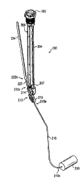
Referring first to FIG. 20, a liquid level gauge sub-assembly 200 including
the in-tank components of a gauge is shown. The sub-assembly 200 comprises a
gauge head 202 and a fixed-length support arm 204 attached to and projecting
away from the gauge head 202. A fixed-length magnet drive shaft assembly (best
seen in FIGS. 25 and 26) is installed in a sideways-securing drive shaft
passage or
channel 209 formed in the support arm 204 so as to prevent lateral and
longitudinal
movement but to allow rotational movement of the installed assembly. The drive
shaft assembly includes a magnet holder 205 at its upper end and a pinion gear
portion 207 at its lower end. A magnet 210 (FIG. 25) is mounted in the magnet
holder 205 at the upper end of the drive shaft assembly such that it is
positioned
within a passage 52 (see FIG. 1 b and. e.g., FIG. 22f) formed in the gauge
head 202.
A pivot arm 212 including a spur gear portion 214 and an arm attachment
portion
2 I6 is pivotally attached to the lower portion of support arm 204 such that
the teeth
of the spur gear portion 214 operably engage the teeth of the pinion gear 207.
Thus, an angular motion of the pivot arm 212 causes a corresponding rotational
motion of the drive shaft assembly and associated magnet 210. A float arm 218
can be attached at a first end 2I 8a to the arm attachment portion 216 of the
pivot
arm 212 and a float 220 can be affixed to the second end 218b of the float arm
218.
A counterweight arm 222 can be attached at a first end 222a to the arm
attachment
portion 216 of the float arm 212 and a counterweight 224 can be mounted at the
second end 222b of counterweight arm 222. In this application, the components
that pivot with the pivot arm 212, including the float arm 218, the float 220,
the
counterweight arm 222, and the counterweight 224, are collectively referred to
as
the float arm assembly and collectively denoted by reference numeral 225. In a
31
CA 02336096 2000-12-27
WO 00/02015 PCT/US99/14059
preferred embodiment of the invention, the float arm 218 is formed integrally
with
the counterweight arm 222.
To form a complete liquid level gauge (FIG. 21 ), a magnetically coupled
indicator dial assembly 226 can be operably attached to the gauge sub-assembly
200. The magnetically coupled indicating dial assembly 226 (FIGS. 21 and 23)
has
a configuration similar to dial assembly 34 (FIGS. 6 and 7) previously
described.
Indicating dial assembly 226 can include a pointer 272 or other visual
indicator of
the liquid level being measured. Alternately, dial assembly 226 can include a
magnetically coupled device such as a variable resistor or a voltage divider
(not
shown) as is known in the art for producing a signal suitable for remotely
reporting
the angular position of the magnet 205 (and hence. for reporting the level
being
measured). In still other embodiments, dial 226 can produce both visual and
remote indications of the level being measured.
Referring now to FIG. 21, a liquid level gauge including gauge sub-
assembly 200 and dial assembly 226 is shown installed in a cylindrical LPG
storage tank 228. The storage tank 228 is a pressure vessel having a
cylindrical
tank wall 230 centered around an elongate axis 232. The outside diameter, d.
of
tank 228 is measured perpendicular to the elongate axis 232. The tank shown in
FIG. 21 has a diameter, d, of approximately 41 inches, however, a liquid level
gauge according to the current invention can be used in storage tanks and
pressure
vessels having a diameter in the range from about 24 inches to about 42 inches
including other standard size tanks having diameters of 30 inches, 31.5
inches, 37
inches and 40.5 inches. For purposes of further description, shown in dashed
lines
in FIG. 21 is a circle, denoted by referenced numeral 235. having a radius 0.5
x d
representing the cross-section of the tank 228 if viewed along the elongate
axis
232. A pressure fitting 234 is provided on the upper portion of tank wall 230
for
32
CA 02336096 2000-12-27
WO 00/02015 PCT/US99/14059
installation of the liquid level gauge along a line perpendicular to the
elongate axis
232. In the embodiment shown, the pressure fitting 234 is an internally
threaded
fitting welded to the tank wall 230. In many regions, the size of the threaded
pressure fitting 234 has been standardized with a minimum internal diameter of
about 1.13 inches.
The liquid level gauge is installed in the tank 228 by first passing the float
arm assembly 225. support arm 204 and other in-tank components of the gauge
through the threaded pressure fitting 234 and then screwing the gauge head 202
into the pressure fitting until a pressure-tight seal is obtained and the
float arm 218
is oriented to move in the desired direction. It is common practice to orient
the
float arm 218 so that it moves in a plane offset about 30° from the
elongate axis
232. however it will be readily apparent that other orientations can be used
provided there is no interference from the tank walls or from other tank
fittings.
While threaded pressure fittings are the most common method of installing
liquid
level gauges in LPG tanks, it will be readily apparent that other pressure-
tight
fittings known in the art, for example, flanged fittings with gaskets. could
be used
without departing from the scope of the current invention.
Referring still to FIG. 21, the liquid level gauge is shown installed in the
tank 228 with the float 220 positioned at the 5% full level of the tank.
indicated by
the dashed line at reference numeral 236 (approximately 4 inches from the
bottom
in a tank having a diameter of 41 inches). As the liquid level rises and falls
in the
tank, the float 220 remains at the surface of the liquid causing the float arm
assembly 225 to pivot correspondingly around pivot axis 248. For example, when
the liquid is at the 80% full level of the tank, indicated by the dashed line
at
reference numeral 238 (approximately 30 inches from the bottom in a tank
having
a diameter of 41 inches), the float arm assembly (shown in phantom for this
33
CA 02336096 2000-12-27
WO 00/02015 PCT/US99/14059
position) will be at the position indicated by reference numeral 240. Between
the
S% full level 236 and the 80% full level 238, the float arm 218 (and thus also
the
float assembly 225) moves through an angle, denoted by reference letter a~,
that
defines the normal working range of the gauge. An intermediate position (again
shown in phantom) for the float arm assembly is shown at reference numeral 242
and an empty position for the float arm assembly (again shown in phantom) is
indicated at reference numeral 244. Note that in the empty position shown at
reference numeral 244, the float arm 218 does not hang vertically downward,
(vertical is indicated by the dashed line at reference numeral 243), but
rather
remains at an angle, indicated by reference letter ak, with respect to
vertical. This
kickoff angle, ak, is maintained to ensure that the float 220 does not reach
bottom
dead center (indicated by reference numeral 246) directly below the float arm
axis
248 as this could cause the gauge to malfunction.
As previously discussed, it is important that the in-tank portions of the
gauge, especially the float arm assembly 225, have adequate clearance from the
inside surfaces of the tank 228 during installation and operation. Referring
still to
FIG. 21, the dashed circle 235 represents the dimensions of a cross-section of
tank
228 if viewed along the elongate axis 232. Circle 23~ can thus be used to
visualize
the position of the in-tank components of gauge in terms of their clearance
with the
inner walls of the tank when the float swings in a plane perpendicular to the
elongate axis 232. As previously discussed, gauges are typically installed
such that
the float arm swings in a plane offset about 30° from the elongate axis
232,
however, the aforementioned situation with the arm swinging perpendicular to
the
elongate axis can occur if gauge 200 is spun rapidly during installation such
that
centrifugal force causes the float ann to rotate from the empty position 244
toward
the 90° (with respect to vertical) position (not shown). Dashed line
250 illustrates
the arc traveled by the radially outermost portion of float 220 as it moves
from the
34
CA 02336096 2000-12-27
WO 00/02015 PCT/US99/14059
empty position 244 to the 80% full level 240. The point (denoted by reference
numeral 252) at which float travel arc 250 intersects tank cross-section
circle 235
indicates where the float 220 will strike the interior of the tank 228 if the
gauge is
turned rapidly. The float arm angle with respect to vertical at the point of
intersection 252 is known as the free-swing angle and is denoted by reference
letter
a,. In a preferred embodiment of the current invention, the free-swing angle
a, is at
least about 25°. In a more preferred embodiment, the free-swing angle
a, within
the range from about 34 ° to about 50 ° .
The free-swing angle as is largely determined by the working length of the
support arm 204 (i.e.. the distance from the top of the support arm to the
pivot axis
248) denoted by reference letter s (FIG. 21 ), and the maximum length of the
float
arm assembly 225 (i.e., the distance from the pivot point 248 to the radially
farthest
point on the float 220) denoted by reference letter f (FIG. 21 ). When the
working
length s of the support arm 204 is selected such that it places the pivot
point 248
within 0.5 x d of the tank bottom and the maximum length f of the float arm
assembly is selected to provide clearance at the bottom of the tank, then the
float
travel arc 250 generally does not intersect with the tank wall, and the swing
angle
a, can be greater than 90 ° (it is then governed only by the internal
travel stops of
the gauge). However, if the working length s of the support arm 204 places the
pivot point 248 too close to the tank bottom, then the float arm will not be
able to
accurately measure high (80%) levels in the tank. ~Che inverse situation is
also a
problem. That is, if the working length s of the support arm 204 is too short,
i.e.,
placing the pivot point 248 significantly further than 0.5 x d from the tank
bottom,
then a float arm having a maximum length f sufficient to measure the low (5%)
levels of the tank will have insufficient free swing angle ag.
CA 02336096 2000-12-27
WO 00/02015 PCT/US99/14059
For single size gauges, i.e., those for use in only one size tank, the method
of choosing an appropriate support arm working length s and float arm maximum
length f is well understood with s typically selected to position the pivot
point 248
at about 0.5 x d above the tank bottom and with f selected to be slightly less
than
0.5 x d. However, it is expensive and thus undesirable to manufacture and
inventory many different gauges for use in tanks of various size. Although the
cost
of manufacturing and inventorying different sized float arm assemblies may be
acceptable due to their relative simplicity, the manufacturing and
inventorying of
different gauge support assemblies (i.e., the gauge sub-assembly less the
float arm
assembly 225) is still undesirably expensive since the gauge support assembly
includes the most expensive portions of the gauge, for example the gauge head,
the
support arm, the gear mechanism and magnet drive shafts, and requires the most
assembly. Thus it has long been a goal of gauge designers to design a single
gauge
support assembly which can be used to make gauge sub-assemblies and gauges for
use in a variety of different sized tanks by subsequently connecting the
proper float
arm assembly and indicator dial to the gauge support assembly. Efforts in this
field
have led to numerous designs incorporating adjustable length support arms or
gauge support assemblies as previously discussed. However, the design of a
fixed-
length gauge support assembly which can be used in a variety of LPG tanks
having
sizes within the range from about 24 inches to about 42 inches in diameter has
heretofore eluded gauge designers. The unique aspects of the current invention
include an embodiment comprising a single fixed-length gauge support assembly
which can be combined with one of a selected group of float arm assemblies and
indicator dial assemblies to form a screw-in gauge which is suitable for use
in LPG
tanks having a range of sizes from about 24 inches to about 42 inches in
diameter,
which provides adequate internal clearance during installation and operation,
and
which provides a high resolution magnetically-coupled indication of the liquid
level.
36
CA 02336096 2000-12-27
WO 00/02015 PCT/US99/14059
Referring now to FIGS. 22a-22g, the gauge head 202 of the preferred
embodiment is substantially similar in form and material to the gauge head 22
previously discussed and shown in FIGS. 8-10, although the proportions of the
gauge head 202 can be adapted as shown in FIGS. 22a-22g to meet the
dimensional
requirements for pressure fittings used on standard LPG tanks. To avoid
repetition,
features common to the gauge heads 22 and 202 are designated with like
reference
numbers and are not described again. While the gauge head 202 of the preferred
embodiment utilizes threads 54 to provide a pressure-tight seal with the
threaded
fitting 234 of the storage tank shown in FIG. 21, it will be apparent that
gauge
heads using a bolted flange (not shown) or other pressure-tight attachment
structure
known in the art can be used on the gauge head of the current invention when
the
storage tanks involved are equipped with an alternative pressure fitting
structure.
Further. while the gauge head 202 of the preferred embodiment includes
recesses 62 which can interfit with the snap-on feet 60 of dial indicators 34
and
226, it will also be apparent that the gauge heads of the current invention
can have
other dial attachment configurations known in the art. for example recessed
portions of the gauge head which can interfit with differently shaped
attachment
tabs on an indicator dial (to provide an index feature) and threaded passages
which
can receive attachment screws which have passed through the attachment tabs.
Referring again to FIG. 2I and now also to FIGS. 6, 7 and 23, the
magnetically-coupled indicator dial assembly 226 can have a plurality of snap-
on
feet 60 and an index tab 78 for securing and aligning the dial assembly 226 to
the
recesses 62 and index slot 76 of the gauge head 202 in a manner substantially
identical to that previously described for dial assembly 34 (FIGS. 6 and 7)and
gauge head 22 (FIGS. 8-10). The dial assembly 226 can have a receiving magnet
64, an indicia plate 271 and a pointer 272 which are sealed inside a non-
magnetic
37
CA 02336096 2000-12-27
WO 00/02015 PCT/US99/14059
case 67 as is known in the art such that the receiving magnet 64 and the
pointer 272
rotate together. When the dial assembly 226 is attached to the gauge head 202,
the
receiving magnet 64 of the dial assembly is proximate to the upper surface 84
of
the gauge head wall 82 while the drive magnet 210 is proximate to the lower
surface 86 of the gauge head wall 82. Since the wall 82 is non-magnetic, the
magnetic field of magnet 210 extends through the wall. The receiving magnet 64
in dial assembly 226 is magnetically urged to align its magnetic field with
that of
the magnet 210, thereby causing the receiving magnet 64 and the connected
pointer
272 (and/or other indicating mechanisms) to rotate to an angular position
corresponding to the angular position of the float arm assembly 225, and hence
also
to the level of liquid in the tank 228.
While the indicator dials 34 and 226 of the preferred embodiments shown
in FIGS. 6,7, and 23 include snap-on attachment feet 60 which can interfit
with the
recesses 62 on the gauge head 202, it will be apparent that the indicator dial
of the
current invention can have other attachment structures known in the art
without
departing from the scope of the current invention. For example, one dial
configuration, known as a "screw-on" dial, includes differently shaped
alignment
tabs which can interfit with corresponding recesses in the top of the gauge
head.
The dial is then held in place with screws running through the tabs and into
the
gauge head.
Referring still to FIG. 23, the indicator dial assembly 226 of the preferred
embodiment provides a high resolution indication of the liquid level within
the
tank 228, i.e., where the angular distance, ad, between the ~% full mark and
the
80% full mark on the gauge dial is at least 180°. An indicia plate 271
is provided
which is visible from the top side of dial assembly 226. Level indicia marks
274
are provided on visible portions of plate 271 at angular positions
corresponding to
38
CA 02336096 2000-12-27
WO 00/02015 PCT/US99/14059
the positions occupied by the pointer 272 for selected liquid levels within
tank 228.
For example, in the embodiment shown in FIG. 23, level indicia marks 274 are
provided at positions representing the position of pointer 272 for liquid
levels
corresponding to 5%, 10%, 20%, 30%, 40%, 50%, 60%, 70%, and 80% of the
S tank's total volume remaining. Note that the angular placement of the level
indicia
marks 274 on the indicia plate 271 takes into account the nonlinear
relationship
between the liquid height and the remaining volume of liquid in a cylindrical
tank,
and also the nonlinear relationship between the float arm angular position and
the
float vertical height. As a result, the angular distance between different
pairs of
adjacent level indicia marks may vary even though the change in percent tank
volume is the same. For example, the angular distance between the 30% and 40%
level indicia marks (denoted by reference number 276} is greater than the
angular
distance between the 40% and 50% level indica marks (denoted by reference
numeral 277), even though each distance represents the same change in
remaining
tank volume. The indicia plate 271 can further include advisory indicia
providing
information to the user, for example, specifying appropriate tank
configuration
(reference numeral 276a), identification of level indicia format (reference
numeral
276b), temperature/LPG mix adjustment charts (reference numeral 276c), and
user
cautions (reference numeral 276d).
By providing indicator dial assemblies 226 having different indicia plates
271, gauges 200 according to the current invention can be assembled using
identical gauge stub assemblies with fixed-length support arms 204 which can
accurately measure liquid levels in different size LPG tanks having diameters
ranging from about 24 inches to about 42 inches, even though the angular range
ar
of the float arm assemblies 225 can vary for tanks of different diameter.
However.
if the float arm range a~ for some tanks in this size range is less than
90° (see, e.g.,
FIG. 21 ), providing a high resolution indication of liquid level, that is,
where ad on
39
CA 02336096 2000-12-27
WO 00/02015 PCT/US99/14059
dial assembly 226 is at least 180 °, requires that the gear ratio
between the gear
portion 214 of pivot arm 212 and the drive shaft gear 207 must be greater than
2: I,
and preferably within the range from 2.0:1 to about 2.5:1.
S Referring now to FIGS. 24a-24e, details of the support arm 204 are shown.
The support arm 204 is similar in some respects to the previously described
support
arm 24 shown in FIGS. 1 I a-1 S. For example, in the embodiment shown in FIG.
24a, the support arm 204 is a one-piece assembly produced from injection
molded
acetal plastic. Other plastics, such as polyester, or other materials such as
metals,
could be used. however. In addition, while a one-piece assembly is preferred,
multiple-piece assemblies can be used without departing from the scope of the
current invention.
In the preferred embodiment, the support arm 204 has a fixed working
I S length s (FIG. 2 I ) within the range from about 10.5 inches to about 14
inches. In a
more preferred embodiment, the fixed working length s is within the range from
about I I.0 inches to about 12.0 inches. A support arm 204 having a fixed
length as
described can be used in a gauge, a gauge sub-assembly or a gauge support
assembly suitable for use in a cylindrical tank having a diameter within the
range
from about 24 inches to about 42 inches.
The support arm 204 comprises an upper portion 254 for attachment to the
gauge head 202, a lower portion 256 for attachment to the pivot arm 212 which
connects the float arm assembly 225, and a middle portion 258 for supporting
the
magnet drive shaft assembly. The support arm 204 is connected to the gauge
head
202 by means of at least one latching member 260. To facilitate easy
attachment of
the support arm 204 to the gauge head 202, in the preferred embodiment two
CA 02336096 2000-12-27
WO 00/02015 PCT/US99/14059
latching members 260 are provided which are adapted to snap fit over the
mounting tabs 90 (see, e.g., FIG. 22b) of the gauge head 202.
To facilitate the alignment of the support arm 204 and the gauge head 202,
and to provide additional structural strength to the joint therebetween,
support arm
204 can also include an internal support member 262 which is adapted to fit
within
the tubular passage 52 (see, e.g., FIG. 22g) of the gauge head 202. The
internal
support member 262 may take the form of a slotted cylinder as shown by member
263 in FIG. 23d. The internal support member can also be formed from two or
more partially cylindrical members (similar to those numbered 104a and 104b in
FIG. 11 c} which provide the desired internal support and, at the same time.
allow
simplified tooling for injection molding. In yet another alternative
embodiment
shown in FIG. 23e, the support member 262 can be a full cylindrical boss 264
which provides further strength to the joint between the support arm 204 and
gauge
head 202. The increased strength and stiffness provided by a full cylindrical
support member is of particular importance where relatively long support arms
or
float arm assemblies are used or where the gauge will be installed in the tank
before it is transported to its final destination. To further ensure proper
alignment
of the support arm 204 with the gauge head 202, an alignment key (similar to
key
108 shown in FIG. 11 b) can be provided which interfits into the index slot 92
(FIG.
22f) in the lower portion of the gauge head.
Referring still to FIGS. 24a and 24b, an important aspect of the support arm
204 which facilitates ease of assembly and low parts count in the current
invention
is the sideways-securing shaft channel 209 formed by the middle portion 258 of
the
support arm along the longitudinal axis 265. The term "sideways-securing"
refers
to the structure of the support arm 204 having shaft securing elements along
the
shaft channel 209 which allow a drive shaft assembly (e.g., 206, 208) to be
laterally
41
CA 02336096 2000-12-27
WO 00/02015 PCT/US99/14059
secured in place by moving it in a sideways motion, i.e., a motion in a
direction
generally perpendicular to the longitudinal axis 265. In the embodiment shown
in
FIGS. 24a-24e, the shaft securing elements include shaft bearings 278 which
are
located in laterally-spaced-apart pairs along the shaft channel. As best seen
in FIG.
24b, the lateral spacing between shaft bearings 278 in each pair can be
selected
such that a drive shaft 206 can be snap-fit between the bearings as it is
moved
sideways into shaft channel 209 toward longitudinal axis 265. It will be
readily
understood that the snap-fitting of the shaft 206 into the shaft channel
includes an
initial interference or blocking between the shaft and the bearings 278 as the
shaft
is moved sideways in shaft channel 209 toward the axis 265 and into contact
with
the bearings. Further sideways movement of the shaft toward the axis 265
(which
may require significant force) causes a deflection of the shaft, bearings
and/or
support arm structure such that the shaft passes between the bearings. A final
interference-free fit results when the shaft 206 is moved further into the
shaft
channel past the bearings 278 and into alignment with longitudinal axis 265.
The
aforementioned final fit is interference-free only in the sense that the
bearings 278
allow unrestricted rotational motion of shaft 206 when it is aligned with the
axis
265; the bearings will, of course, resist any lateral motion of the shaft 206.
Thus,
the bearings 278 secure the shaft assembly in the shaft channel 209.
If the support arrn 204 has a slotted support member, for example, support
member 263 in the embodiment shown in FIG. 24d, then the drive shaft assembly
206, 208 can be inserted into the shaft channel 209 with a purely sideways
motion,
as with the side-accessible shaft channel discussed in previous embodiments of
the
invention. If, however, the support arm 204 has a full cylindrical support
member,
for example, support member 264 in the embodiment shown in FIG. 24e, then the
drive shaft 206 is installed in a different manner as follows: First, the
upper drive
shaft 206 is inserted from the top of support arm 204 through the passage 267
42
CA 02336096 2000-12-27
WO 00/02015 PCT/US99/14059
formed through support member 264 and with the shaft being directed at a
slight
angle (with respect to longitudinal axis 265) as it exits the passage. The
angle will
allow the shaft 206 to be positioned adjacent to the securing bearings 278 but
on
the opposite side of the bearings from longitudinal axis 265. Next, the shaft
206 is
longitudinally positioned at the desired location with respect to channel 209,
typically by aligning grooves or flanges on the shaft with corresponding
features on
the channel. Finally, the shaft 206 is secured in the shaft channel 209 by
moving it
sideways into the channel toward the longitudinal axis 265 until it is engaged
by
the sideways securing elements (in this case, bearings 278) and is aligned
with the
longitudinal axis.
The lower drive shaft 208 can be operably connected to the upper drive
shaft 206 either before or after the upper drive shaft is secured in channel
209,
depending on the interconnection elements used. The lower shaft 208 can be
secured into the shaft channel 209 using a sideways movement and bearings 278
similar to those previously described. In the embodiment shown in FIGS. 25-26,
the connecting pin 211 a of shaft 206 can be inserted into the slot 211 c of
shaft 208
after the shaft 206 has been inserted through the support member (e.g., member
264 (FIG. 24e)) and then the joined shafts 206 and 208 can be concurrently
moved
sideways to secure them in shaft channel 209.
The sideways-securing shaft channel is a great improvement because it
allows the magnet drive shaft assembly to be installed into the support arm
204
even if the drive shaft assembly has features such as flanges or connectors
which
are too large to slide longitudinally through the bearings along the axis 265.
Instead, the shaft and its oversized components can be moved into longitudinal
position adjacent to the bearings and then moved sideways to secure the shaft
into
place. The side-securing shaft passage also allows the use of mufti-piece
magnet
43
CA 02336096 2000-12-27
WO 00/02015 PCT/US99/14059
drive shaft assemblies (e.g., 206, 208) wherein the shafts are connected to
one
another after at least one of the shafts has been longitudinally positioned in
the
shaft channel. In addition, the sideways securing shaft channel 209 allows
shaft
bearings 278, 280 to be formed as an integral part of support arm 204 rather
than
requiring them to be separate parts.
As best seen in FIG. 24b, in the preferred embodiment the sideways
securing shaft channel 209 is formed by the U-shaped combination of side walls
282 and back wall 284 that form the middle portion 258 of the support arm 204.
To provide additional structural support and rigidity, in the preferred
embodiment,
the middle portion 258 of the support arm 204 further comprises longitudinal
support members 286 attached to the outer portion of side walls 282. In
embodiment shown in FIGS. 24a and 24b, the support members 286 form holes
288 to reduce material usage without significantly affecting the rigidity of
the
support arm 204. It will be readily apparent that other configurations for the
middle portion of the support arm can be used to provide the sideways securing
drive shaft channel without departing from the scope of the current invention.
The lower portion 256 of the support arm 204 is adapted for pivotal
connection to the pivot arm 212 (FIGS. 27a-27d). In a preferred embodiment,
the
bottom portion 256 forms a passage 270 for receiving a pivot pin or axle 288
(FIGS. 27a-27d) of the pivot arm 212; however, it is apparent that the
relative
locations of the axle 288 and passage 270 on the support arm 204 and pivot arm
212 can be reversed. In the preferred embodiment, axle 288 is retained in
passage
270 by the subsequent attachment of retainer 289, however, other retaining
mechanisms could be used as previously described or known in the art. To
control
the overall travel of the float arm assembly and maintain the kickoff angle
ak, an
internal float stop is provided on the pivot arm 212 and the support arm 204.
As
44
CA 02336096 2000-12-27
WO 00/02015 PCT/US99/14059
previously discussed, the float stop is considered internal where its
components are
not exposed on the outside surface of the gauge, thus minimizing the
possibility
that the float stop mechanism will be contaminated by any debris within the
tank.
In a preferred embodiment, the internal float stop comprises a keyway 290
(FIG.
24a) that is formed on suppork arm 204 in a partial arc surrounding axle
passage
270 to interfit with a key 292 (FIGS. 27b-27d) formed on the pivot arm 212. In
this preferred embodiment, lower portion 256 also forms a shaft gear passage
294
allowing the pinion gear 207 clearance to turn freely when the shaft assembly
has
been installed in shaft channel 209.
Referring now to FIGS. 27a-27d, the pivot arm 212 of the current invention
has several unique features adapted to meet the requirements of LPG tank
service.
As previously described, the pivot arm 212 includes a spur gear portion 214
and an
arm attachment portion 216. The spur gear portion 214 includes gear teeth 304
arranged in an arc around a center point 306. The maximum radial extent of the
teeth relative to center point 306 defines a maximum radius for the gear. The
gear
ratio between the spur gear portion 214 of pivot arm 212 and the pinion gear
207 of
the shaft assembly will determine the dial angle ad obtained for a float arm
range
angle a~. To allow the desired dial angle ad of at least 180° with a
range angle a~
which can be 90 ° or less for some size tanks, the ratio between the
gears 214 and
207 is preferably at least 2: I and more preferably within the range of 2.0: I
to about
2.5:1. Consequently, the angular spacing of the teeth on the pinion gear 207
is
preferably in the range of 2.0 to about 2.5 times the angular spacing of the
teeth on
the spur gear portion 214. For example, in the preferred embodiment, the
pinion
gear 207 has 6 teeth evenly spaced at approximately 60 ° to one another
and the
spur gear portion 214, if it was a full circular gear, would have 15 teeth
evenly
spaced at approximately 24 ° to one another. However, for reasons
discussed
below, the spur gear portion 214 in this embodiment is not a full circular
gear, but
CA 02336096 2000-12-27
WO 00/02015 PCT/US99/14059
instead is a partial gear, also called a sector gear, having only 6 full
teeth.
However, the teeth 304 of spur gear portion 214 are arranged in an arc about
center
point 306 with approximately 24 ° spacing to one another such that the
desirable
gear ratio of 2.5:1 is obtained between the gears 214 and 207.
The spur gear portion 214 on the pivot arm 212 can be made with only a 6-
tooth sector gear rather than a full 15-tooth circular gear because only 6
teeth of the
spur gear will actually engage the pinion gear 207 as the pivot arm 212 moves
through its range of motion. Any additional teeth on the spur gear portion 214
would therefore be unused. By forming the pivot arm 212 with only 6 teeth,
rather
than with 15, the tooling required to produce the pivot arm is simplified,
resulting
in a significant savings in tooling costs.
Further, the use of a full circular gear having 15 teeth formed at the same
1 S maximum radius as the teeth on the spur gear portion 214 would result in
the pivot
arm 212 being too large to fit through the standard I .13 inch opening found
on
many LPG tanks. Thus, as best seen in FIG. 27c, the pivot arm ? 12 of the
current
invention includes a spur gear portion 214 which is not a full circle, but
instead is
an arc of radially arranged gear teeth, the arc having an angular extent of
less than
180° and a center 306 which is laterally offset with respect to the
center of the
shortest lateral side of the pivot arm (i.e., the lateral distance w, from the
center 306
to the left side of stub arm 212 is smaller than the lateral distance w~ from
the
center 306 to the right side, where w, + w~ is the length of the minimum
lateral
dimension of the pivot arm). Thus, the gear teeth 304 on spur gear portion 214
can
be sized to have a maximum radius (measured from center 306) which is
significantly greater than 0.5 times the minimum lateral width (w, + w~) of
the stub
arm. This unique configuration allows the pivot arm 212 to have gear teeth
with a
46
CA 02336096 2000-12-27
WO 00/02015 PCT/US99/14059
robust maximum radius on gear portion 214 while still being able to pass
through
the standard 1.13 inch tank opening.
Another important aspect of the current invention is the support arm 204
S having a lower section which is front-laterally offset with respect to the
longitudinal axis 265 and which has an angled front-lateral profile. For
purposes
of this application, the term "front-lateral" refers to the lateral directions
when
viewed from the front side of the object. For example, in the support arm 204
shown in FIG. 24a, the front-lateral direction, indicated by dashed line 296,
is
generally perpendicular to a plane containing both the longitudinal axis 265
and the
float arm pivot axis 248. As best seen in FIG. 24c. the front-lateral offset
of the
support arm 204 complements the offset configuration of the pivot arm 212 when
the gauge is configured for installation into the tank (i.e., when the
counterweight
224 is tucked up against the longitudinal support member 286). In this
complementary position, the individual gear teeth 304 of gear portion 2I4 are
protected from contacting the edges of the threaded pressure fitting 234
during
installation of the gauge 200 by the greater lateral extent (denoted by
reference
numeral 30~) of the lower portion of the support arm 204.
Refernng now again to FIG. 24a, the front lateral offset of the support arm
204 is further described. FIG. 24a shows the support arm 204 without the float
arm
assembly. The drive shaft passage 209 of support arm 204 runs along
longitudinal
axis 265. terminating at the opening 294 for the shaft gear 207. The upper
portion
298 of float arm 204 (the portion above dashed line 300 in FIG. 24a) has an
overall
lateral width w~ defined by the front lateral extent of the support members
286
which are generally symmetrically arranged on both sides of the longitudinal
axis
265 (each extending laterally from the axis about 0.5 x w~). The lower portion
302
of the float arm (the portion below dashed line 300 in FIG. 24aj comprises a
47
CA 02336096 2000-12-27
WO 00/02015 PCT/US99/14059
portion of the float arm middle 258 and the entire float arm bottom 256 having
the
pivot arm attachment passage 270. As best seen in FIG. 24a, the front lateral
extent of the lower portion 302 of the float arm 204 is not symmetrically
arranged
around the longitudinal axis 265. Instead, the lower portion 302 is front
laterally
offset with respect to the longitudinal axis 265. In the example shown in FIG.
24a,
the left lateral extent w,g adjacent to float arm pivot axis 248 is smaller
than the
right lateral extent w~s. Note, however, the overall width wa of the lower
portion
302 is about the same as the width w~ for the upper portion 296. This front
lateral
offset allows the lower portion 302 of the support arm 204 to have a lateral
extent
on one side of the pivot axis 248 which is much greater than 0.~ times the
overall
width wa of the lower portion while at the same time keeping wa approximately
equal to w~ (the overall width of the upper portion). This allows the lower
portion
302 to provide protection for the offset gear portion 214 of the stub arm 212
(when
in the installation position) while still allowing the assembled gauge 200 to
fit
1 ~ through the opening in the pressure fitting 234 having a diameter only
slightly
larger than w".
The lower portion 302 of the support arm 204 also has an angled front
lateral profile with respect to upper portion 296. The centerline of lower
portion
302. denoted by dashed line 303. forms an angle a° with the
longitudinal axis 265.
In the preferred embodiment, ao is about 7°. The angled front lateral
profile of
lower portion 302 allows the support arm 204 to be smoothly inserted through
the
narrow opening of pressure fitting 234 during installation without catching or
binding.
Referring again to FIGS. 27a-27d, another important aspect of the current
invention is the attachment portion 216 of the stub arm 212. In the preferred
embodiment, the attachment portion 216 has snap-in fastening features 310
adapted
48
CA 02336096 2000-12-27
WO 00/02015 PCT/US99/14059
to flex open as a wire such as float arm 218 is inserted therein and then
close to
securely retain the wire in place. In addition, the attachment portion 216
includes
at least two fastening features 310 having wire guide paths which are non-
collinear
or disposed at an angle to one another. This prevents the round float arm wire
218
from rotating relative to the stub arm 212 after installation without
requiring any
set screws or other supplemental holding devices. In the preferred embodiment
shown in FIGS. 27a-27d, three fastening features 3I0 are provided having wire
guide paths 312, 314 and 316, respectively, positioned with approximately
90°
angles between each subsequent guide path to form a "z" shaped path for wire
218.
As best seen in FIG. 28b, the float arm wire 218 has a corresponding "z"
shaped
section, designated by reference numeral 318, which can be snapped into the
fastening features 310 of the pivot arm.
Referring now to FIGS. 25 and 26, in the preferred embodiment, the drive
shaft assembly is a multi-piece assembly comprising an upper magnet drive
shaft
206 and a lower magnet drive shaft 208 which are connected together such that
torque can be transmitted between the two drive shafts. The upper magnet drive
shaft 206 includes the magnet holder 205 at its upper end 206a and the lower
magnet drive shaft 208 includes the gear portion 207 at its lower end 208b.
The
drive shafts 206, 208 can further include axial alignment members 206c, 208c,
respectively, which keep the drive shafts from shifting axially within the
drive
shaft channel 209. Such axial shifting could put undesirable pressure on the
gears
207, 214 or move the magnet 210 from its proper position. While any type of
axial
shaft alignment structure known in the art can be used for the alignment
members,
in the preferred embodiment shown in FIG. 25 the alignment members 206c, 208c
are raised flanges which interfit with corresponding grooves formed along the
sides
of alignment channel 209 on the support arm 204.
49
CA 02336096 2000-12-27
WO 00/02015 PCT/US99/14059
Referring now still to FIGS. 25 and 26, the lower end 206b of the upper
magnet drive shaft 206 and the upper end of 208a of the lower magnet drive
shaft
208 include connecting members (best seen in FIG. 26) which can be
interconnected to one another such that torque can be transmitted from one
drive
S shaft to the other while permitting limited axial movement of the adjacent
shaft
ends 206b, 208a with respect to one another. Even though the support arm 204
has
a fixed length, the use of a mufti-piece drive shaft assembly allowing axial
movement between the adjacent ends of drive shafts 206, 208 is of considerable
practical benefit as it allows dimensional variation in the length of the
individual
I O drive shaft components to occur without biasing the outer drive shaft ends
206a,
208b to move from their nominal positions (as fixed by the axial alignment
members). Any bias on the outer drive shaft ends 206a, 208b to move from their
nominal positions can cause binding of the alignment members 206c, 208c
against
the support arm 204 which can considerably increase the operating torque and
15 accuracy of the gauge. Dimensional variation can occur either due to
variations in
manufacturing of the shafts 206, 208 and/or support arm 204, or due to thermal
expansion and/or contraction of these components which can occur when the
gauge
is exposed to temperature extremes in service. In the preferred embodiment
shown
in FIGS. 25 and 26, the connecting members comprise a pin 21 la which projects
20 from a first half shaft section 211 b on upper shaft end 206b to interfit
with a slot
211 c formed in a second half shaft section 211 d on lower shaft end 208a. The
members 211 a and 211 c are initially interconnected by lateral relative
movement
which can be accomplished prior to installation into the support arm 204
through
the sideways securing shaft channel 209. The pin 211 a can transmit torque to
the
25 sides of the slot 211 c while remaining free to move axially. It will be
readily
apparent, of course, that other connecting mechanisms known in the art for the
transmission of torque between shafts while allowing limited axial movement,
for
example, splined shafts, telescoping circular shafts with an index key, and
CA 02336096 2000-12-27
WO 00/02015 PCT/US99/14059
telescoping polygonal tubular members, could be used for the connecting
members
without departing from the scope of the current invention.
Referring now to FIGS. 28a-28b, another aspect of the current invention is
the configuration of the float arm 218 and counterweight wire 222 (if used).
In the
preferred embodiment, the float arm 218 and the counterweight arm 222 are
formed from an integral piece of wire, however, it will be understood that the
arms
218 and 222 can be formed separately and joined, for example, at pivot arm
212,
and that the counterweight arm 222 can be omitted under certain circumstances.
As previously discussed, the exact dimensions of the float arm wire used in
LPG
tanks having diameters in the range of about 24 inches to about 42 inches will
vary.
However, the current invention utilizes a standard float arm/counterweight arm
configuration having defined parameters which can be specified to adapt the
float
arm assembly 225 to fit a specific size tank having a diameter of about 24
inches to
about 42 inches while the remaining components of the gauge 200, including the
support arm 204 and the pivot arm 212, remain unchanged.
The float 220 is buoyant in LPG and provides sufficient buoyancy to remain
at the surface of the liquid when connected to the float arm 218. In the
preferred
embodiment, the float 220 is formed of solid (i.e., not hollow) nitrite rubber
foam,
however, it will be readily apparent that the float can be formed of other
materials
including plastics, metal and cork. and in other configurations including
hollow, as
is known in the art provided the overall dimensions of the float arm assembly
do
not change significantly.
FIGS. 28a-28b show a scale view of a float arm assembly suitable for use in
a 24-inch diameter tank where the working length s of the support arm 204 is
within the range of about 11 to 12 inches. For reference purposes, the float
220 in
51
CA 02336096 2000-12-27
WO 00/02015 PCT/US99/14059
FIGS. 28a-28b is approximately 1.1 inches in diameter and approximately 2.5
inches in length. The portion of float arm 218 extending from the float 220
has a
first section 320 (FIG. 28a) having a large radius curve necessary to allow
float arm
218 to follow the float 220 through the narrow opening of the threaded
pressure
fitting 234. In the preferred embodiment, the large radius curve 320 has a
radius of
at least about one inch. The curved section 320 of wire 218 is integrally
connected
to a first straight section 322 having a f xed length, h, for all tank sizes.
In the
preferred embodiment, the length l, of first straight portion 322 is within
the range
of about 5 inches to about 6 inches. The first straight section 322 is
integrally
connected by first bend 324 to a second straight section 326 having a length
1,.. In a
preferred embodiment for 24 inch tanks, length l,, is about 3 inches for 24
inch
tanks. In other embodiments for tanks having a diameter from about 24 inches
to
about 42 inches, length I,. is within the range from about 3 inches to about
21
inches. As best seen in FIG. 28b, second straight section 326 is bounded on
the
lower side by the first bend 324 and bounded on the upper side by a second
bend
328 which is positioned just outside the attachment portion 216 of pivot arm
212.
Viewed from the front, the second straight section 326 of float arm 218 also
forms
an angle a,, with a line constituting an extension of the section (denoted by
316a)
extending from fastening feature 310 of the stub arm 212 along support path
316.
In the preferred embodiment for 24 inch tanks, angle a,, is about 21 °.
In other
embodiments for tanks having a diameter from about 24 inches to about 42
inches,
angle a~ is within the range from about 21 ° to about 0°. After
second bend 328.
float arm 218 sequentially forms sections 316a, 314a and 312a corresponding in
shape to the wire guide paths 316, 314 and 312, respectively, of pivot arm
212.
These three sections, collectively denoted as the "z" shaped section 318, have
the
same dimensions for all embodiments of float arm 218 such that a common pivot
arm 212 can be used for all size tanks. After exiting the z-shaped section
318, the
wire, now referred to as counterweight arm 222, first forms a third straight
section
52
CA 02336096 2000-12-27
WO 00/02015 PCT/US99/14059
329 constituting an extension of section 312a and having a length le which is
fixed
for all size tanks. In the preferred embodiment le is within the range of
about 2
inches to about 3 inches, measured from the last 90° bend in section
318. In a
more preferred embodiment, le is about 2.6 inches. The upper end of section
329 is
bounded by a third bend 331. The third bend 329 connects to a tail section 330
which allows attachment of the counterweight 224. As best seen in FIG. 28b,
the
tail section 330 forms an angle a~ with a line constituting an extension of
tail third
straight segment 329. The angle a~ is fixed for all size tanks and allows the
counterweight 224 to f t snugly against the support arm 204 during
installation. In
the preferred embodiment, angle a~ is about 7°. The length h of the
tail segment
330 and the length h of the counterweight 224 are selected. based on the
composition of the counterweight, to provide the force necessary to adequately
supplement the buoyancy of Moats 220 as known in the art.
1 S Thus, there is disclosed a float-type liquid level gauge that overcomes
the
shortcomings and disadvantages of the prior art liquid level gauges. While the
foregoing embodiments of the invention have been disclosed with reference to a
specific gauge structure, it is to be understood that many changes in detail
may be
made as a matter of design choices, without departing from the spirit and
scope of
the invention. as defined by the appended claims.
53