Note: Descriptions are shown in the official language in which they were submitted.
CA 02336581 2001-01-04
WO 00/09863 PCT/US99/17681
MISMATCH PROOF VARIABLE STATOR VANE
BACKGROUND OF THE INVENTION
The present invention relates generally to gas turbine engines, and, more
specifically, to variable stator compressor vanes.
A typical gas turbine engine compressor includes several rows or stages
of compressor stator vanes and corresponding rows or stages of compressor
rotor blades therebetween. During operation, air is sequentially compressed in
the compressor stages and channeled to a combustor for being mixed with fuel
and ignited for generating hot combustion gases which power the engine.
Compressor performance is improved by providing variable stator vanes
which are selectively rotated about their longitudinal or radial axes. This is
accomplished by attaching a corresponding lever arm to th~e radially outer
ends
of the vanes and joining the several levers to a common actuation or unison
ring
for providing uniform adjustment of the individual vanes to maximize
compressor
performance.
Each of the variiable vanes must be identically angled relative to the other
vanes in the row to maximize efficiency and prevent undesirable aerodynamic
distortion from a misaligned stator vane.
In order to ensure proper alignment of the individual stator vanes, each
vane typically includes a generally D-shaped seat around which a
complementary D-shaped mounting hole of the lever is positioned. A threaded
stem extends from the seat and receives a nut which secures the individual
1
CA 02336581 2001-01-04
WO 00/09863 PCT/[JS99/17681
levers to the corresponding vanes.
The lever mounting holes and corresponding vane seats are typically
sized with close manufacturing tolerances to ensure accurate coordination of
the
rotary positions of the vanes during operation. For example, the flat parallel
sides of the seat and mounting hole are typically sized with a line-to-line
clearance which is nominally a zero clearance plus or minus a suitable
manufacturing tolerance. Statistically, this means that some levers will have
a
positive clearance around their seats and are readily seated thereon, and some
levers will have a negative clearance around their seats which requires a
corresponding assembly force resulting in a tight interference fit with their
seats.
The interference fit is typically effected by simply threadingly engaging the
retaining nut atop the threaded stem and torquing the nut sufficiently to
drive the
lever downwardly around its seat in an interference fit therewith. This,
however,
presents the problem of plasticaily damaging either the lever or its seat in
the
event of misalignment therebetween.
Since the mounting hole of a lever in the interference fit example cannot
initially engage its corresponding seat, when the nut is initially threaded
atop the
exposed portion of the stem it hides from view the D-shaped interface between
the mounting hole and its seat. If the lever is misaligned atop its seat and
the nut
is nevertheless torqued into engagement, undesirable plastic deformation
around the mounting hole or seat, or both, can occur requiring replacement of
either or both components.
Accordingly, it is desired to provide an improved variable stator vane
which prevents mismatch assembly between the lever atop its mounting seat.
2
CA 02336581 2001-01-04
WO 00/09863 PCT/US99/17681
BRIEF SUMMARY OF THE INVENTION
A variable stator vane includes an airfoil having a threaded stem, a lever
having a mounting hole receiving the stem, and a nut threadingly engaging the
stem to retain the lever on the airfoil. A clearance is provided between the
seat
and lever during alignment 'therebetween to provide sufficient thread overlap
between the nut and stem to permit engagement therebetween, with insufficient
thread overlap being provided during misalignment to prevent threaded
engagement therebetween.
BRIEF DESCRIPTION OF THE DRAWINGS
The invention, in accordance with preferred and exemplary embodiments,
together with further objects and advantages thereof, is more particularly
described in the following detailed description taken in conjunction with the
accompanying drawings in which:
Figure 1 is a partly sectional, elevational view of a variable stator
compressor vane mounted in a multistage axial compressor of a gas turbine
engine in accordance with an exemplary embodiment of the present invention.
Figure 2 is a top, partly sectional view through a mounting portion of the
variable vane illustrated in Figure 1 and taken along line 2-2.
Figure 3 is an exploded view of the variable stator vane illustrated in
Figure 1.
3
CA 02336581 2001-01-04
WO 00/09863 PCT/US99/17681
Figure 4 is a partly sectional, elevational view of the outer poraon of the
variable vane illustrated in Figure 3 during misalignment assembly of the
lever
atop its mounting seat and taken generally along line 4-4.
Figure 5 is a partly sectional, elevational view of the outer portion of the
variable vane illustrated in Figure 3 during alignment assembly of the lever
atop
its mounting seat and taken generally along line 5-5.
DETAILED DESCRIPTION OF THE INVENTION
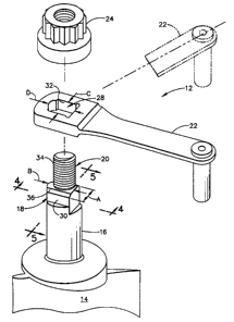
Illustrated in Figure 1 is a portion of an annular stator casing 10 of an
exemplary multistage axial compressor for a gas turbine engine to which is
mounted a plurality of circumferentially spaced apart compressor variable
stator
vanes 12. Each vane includes an airfoil 14 conventionally including a leading
edge, trailing edge, and pressure and suction sides extending therebetween.
Each vane further includes a radially outer trunnion 16 extending coaxially
and integrally outwardly from the top of the airfoil for pivotally mounting
the airfoil
in a corresponding bushing in the casing in a conventionally known manner. In
the exemplary embodiment illustrated, the vane also includes a radially inner
trunnion mounted in a sealing ring, although in other embodiments they may not
be used.
In order to selectively rotate the airfoil 14 during operation, the airfoil
further includes a generally D-shaped seat 18 as illustrated in Figure 2 which
extends radially outwardly from the trunnion 16 as illustrated in more detail
in
Figure 3. A threaded stem 20 extends radially outwardly from the seat and
coaxially therewith around a radial axis of the engine.
4
CA 02336581 2001-01-04
WO 00/09863 PCT/US99/17681
As shown in more detail in Figure 3, the stem 20 is cylindrical with a
substantially constant outer diameter, whereas the seat 18 is unidirectional
in an
exemplary D-shaped configuration below the stem to provide a self-alignment
feature for mounting a lever arm 22 atop the airfoil 14 for selective rotation
thereof during operation. The lever 22 is secured to the airfoil by a threaded
retaining nut 24, shown fully assembled in Figure 1. Each lever 22 has a
distal
end, having a mounting pin for example, which cooperates with an annular
actuation or unison ring 26 in a conventional manner for simultaneously
rotating
in unison each of the airfoils 14 in an individual compressor stage.
As shown in Figures 2 and 3, the lever 22 includes a proximal end having
a mounting hole 28 which is also unidirectional in a generally D-shaped
configuration being complementary with the corresponding seat 18 around which
it is seated.
During assembly, the lever 22 is positioned atop the seat 18 as shown in
Figure 3, with the corresponding D-shaped seat 18 and mounting hole 28
allowing alignment therebetween solely in one matched direction, as shown in
solid line, with all other orientations of the lever 22 atop the airfoil 14
being
unmatched or misaligned, as shown in part phantom in Figure 3 for example.
As indicated above in the Background section, it is desired to prevent
engagement of the nut 24 atop the threaded stem 20 when the lever 22 is
misaligned with the airfoil 14 to prevent the inadvertent torquing of the nut
from
damaging either the mounting hole 28 or the seat 18, or both.
In accordance with the present invention, a method of preventing
mismatched assembly engagement of the lever 22 atop the seat 18 includes
providing insufficient thread overlap between the nut 24 and the stem 20 to
prevent threaded engagement therebetween during misalignment of the lever.
and vane, and providing sufficient thread overlap between the nut and stem to
5
CA 02336581 2001-01-04
WO 00/09863 PCT/US99/17681
permit threaded engagement therebetween during alignment of the lever and
vane.
This method is effected by providing means in the form of a suitable
clearance between the seat 18 and the mounting hole 28 of the lever 22 at the
aligned or matched configuration relative to the misaligned or unmatched
configuration for perrnitting at least partial threaded engagement of the stem
20
and the nut 24. By preventing engagement of the nut 24:with the stem 20 when
the lever 22 is misaligned, torque cannot be applied to the nut and no damage
can be done. Only when the lever 22 is properly aligned with the airfoil 14
does
sufficient thread overlap exist between the nut 24 and the stem 20 for
permitting
threaded engagement therebetween and the application of torque for completing
the assembly.
More specifically, the seat 18 as illustrated in Figures 2 and 3 preferably
includes a pair of opposite, parallel side flats 30 which define a width A of
the
seat. The seat 18 also has an arcuate front and a flat back which define
therebetween a length B of the seat. The seat 18 is preferably narrower in
width
A than in length B.
Correspondingly, the mounting hole 28 includes a pair of opposite,
parallel side walls 32 spaced apart at a width C. The mounting hole 28 also
includes a generally arcuate front and a flat back which are spaced apart over
a
length D. The hole width C is less than the hole length D to correspond with
the
configuration of the seat 18 and allow alignment therebetween in solely the
one
matched engagement therebetween.
The hole width C is preferably nominally equal to the seat width A to
permit seating of the lever around the seat in alignment therebetween. The
hole
width C is also less than the seat length B to prevent seating therebetween
when
misaligned. An example of misalignment between the lever atop the seat 18 is
6
CA 02336581 2001-01-04
WO 00/09863 PCT/US99/17681
illustrated in Figure 4, and alignment therebetween is illustrated in Figure
5, as
well as in Figures 2 and 3.
In the matched orientation, the side walls 32 of the mounting hole may
pass downwardly over the corresponding flats 30 of the stem. Correspondingly,
the arcuate front of the mounting hole 28 passes downwardly over the arcuate
front of the seat 18, and the flat back of the mounting hole passes downwardly
over the flat back of the seat. In all other orientations of the lever 22 atop
the
seat 18, the D-shaped configurations of the mounting hole and seat prevent the
lever 22 from being depressed atop the seat 18 with normal force.
As indicated above, the hole width C is preferably nominally equal to the
seat width A in a preferred line-to-line contact having zero clearance with a
suitable plus and minus manufacturing tolerance. This means that some levers
22 will have a positive side clearance allowing unrestrained assembly of the
lever atop its corresponding seat, whereas other levers 22 will have a
negative
side clearance which prevents or restrains assembly of the lever atop the
seat.
In this latter situation, it is desired to prevent threading engagement of the
nut 24
atop the stem 20 during misalignment of the lever 22 to prevent damage
therebetween upon inadvertent torquing of the nut.
In accordance with the present invention, the nut 24 may threadingly
engage the stem 20 only in the matched orientation of the lever 22 in
alignment
with the seat 18.
As shown in Figure 4, the stem 20 has a height or length E of continuous
threads 34 which is insufficient for threadingly engaging the nut 24 during
the
misalignment orientation illustrated. When misaligned, the bottom of the lever
22
merely sits atop the seat 18 in view of the narrower hole width C relative to
the
larger seat length B. However, by providing respective chamfers 36 atop
corresponding ones of the seat flats 30, a radial or vertical clearance is
provided
7
CA 02336581 2001-01-04
WO 00/09863 PCT/US99/17681
therealong so that the same length E of stem threads 34 is also sufficient for
engaging the nut 24 during the matched or aligned orientation as illustrated
in
Figure 5, with the side walls 32 initially engaging the seat chamfers 36.
The chamfers 36 are preferably provided in the seat 18 and locally
decrease the width of the seat 18 at its top where it joins the stem 20. The
chamfers 36 are only provided on the flats 30 and not along the front or back
of
the seat. It is noted that chamfers may also be provided in the bottom of the
mounting hole 28, but should be limited in extent to prevent an undesirable
decrease in available load bearing area on the side walls 32.
As shown in Figures 2 and 3, the seat chamfers 36 are preferably flat and
extend completely along the seat flats 30 between the arcuate front and flat
back
of the seat. The chamfers 36 therefore correspond with the matched orientation
of the hole side walls 32 as shown in Figure 5 so that when the lever 22 is
placed
atop the seat 18, it is permitted to drop an additional amount corresponding
with
a preferred number of overlapping threads between the stem 20 and the nut 24.
More specifically, and referring to Figure 4, the lever 22 has a thickness F
at the mounting hole which is less than the stem length E, and the nut 24
includes threads 38 for engaging the stem threads 34. And, the nut 24 also
includes an unthreaded counterbore 40 disposed coaxially below its threaded
portion.
The nut counterbore 40 has a height G, and the sum of the counterbore
height G and the lever thickness F are collectively greater than the threaded
stem length E to prevent threaded engagement of the stem and nut during
misalignment.
The seat chamfers 36 have a height H as illustrated in Figure 4, and the
sum of the chamfer height H"and the stem length E is collectively greater than
8
CA 02336581 2001-01-04
WO 00/09863 PCT/US99/17681
the sum of the lever thickness F and counterbore height G collectively to
permit
threaded engagement of the stem and nut during alignment as illustrated in
Figure 5.
As illustrated in Figure 4, when the lever 22 sits atop the seat 18 in
misalignment, the stem thread length E is insufficient to engage the threads
of
the nut 24 placed atop the lever 22. The nut 24 therefore cannot possibly
engage the threads of the stem which prevents the inadvertent misalignment
assembly of the lever and the airfoil.
However, when the lever 22 is rotated atop the seat 18 into the single
matched or aligned orientation shown in Figure 5, the lever 22 may drop the
additional clearance amount up to the height H of the chamfers which exposes
additional stem threads atop the lever 22 and allows the nut 24 to be tumed to
initially engage the top thread portions of the stem 20. The nut 24 may then
be
additionally tumed and torqued atop the lever 22 engaging additional threads
and driving the lever 22 downwardly over the seat flats 30, irrespective of
interference therebetween, until the lever 22 bottoms atop the trunnion 16 as
shown in phantom in figure 5.
As shown in Figure 5, the chamfers 36 have a chamfer angle J which is in
the exemplary range of about 5 to about 7 . The smaller the chamfer angle,
the
more vertical clearance H will be provided. However, the various dimensions of
the assembly, including the seat width A and hole width C, are subject to
typical
manufacturing tolerances such as about plus or minus 0.5 mils (0.0127 mm).
Similarly, manufacturing tolerances are also found for the chamfer angle J
and the associated chamfer height H. These various dimensions may be
selected in compromise to maintain a close tolerance fit between the mounting
hole 28 and the complementary seat 18 while providing insufficient thread
overlap in the misaligned orientation and sufficient thread overlap in the
matched
9
CA 02336581 2004-07-22
WO 00/09863 PCT/US99/17681
and aligned orientation.
In a preferred embodiment, the stem and nut threads 34,38 have a
common pitch selected for initially engaging at least about one and a half
threads
during the matched, alignment orientation illustrated in Figure 5 before the
nut is
torqued down. In this way, sufficient torque may then be exerted on the nut
and
reacted through the initial one and a half thread engagement with the stem to
overcome interference friction between the side walls 32 and the seat flats 30
without damaging the threads. Increasing the number of initial thread overlap
requires a corresponding increase in the vertical clearance H provided by the
chamfers 36, which correspondingly increases the side clearances between the
mounting hole 28 and the seat 18 which is undesirable.
A combination of the unidirectional seat 18, limited stem thread length E,
and limited vertical clearance H provided by the chamfers 36 effects both
insufficient thread overlap when the lever 22 is misaligned as well as
sufficient
thread overlap when the lever is properly aligned. The nut counterbore 40
cooperates with this dual-orientation design and accommodates the exposed
portion of the seat 18 upon bottoming of the lever 22 and allows a suitable
number of nut threads 38 for reacting the retention loads carried by the nut.
While there have been described herein what are considered to be
preferred and exemplary embodiments of the present invention, other
modifications of the invention shall be apparent to those skilled in the art
from the
teachings herein, and it is, therefore, desired to be secured in the appended
claims all such modifications as fall within the true spirit and scope of the
invention.