Note: Descriptions are shown in the official language in which they were submitted.
CA 02336616 2001-O1-04
WO 00/01882 PCT/FI99/00579
FOAM PROCESS IMPLEMENTATION US1NG FUZZY CONTROLLERS
BACKGROUND AND SUMMARY OF THE INVENT10N
When effectively practicing the foam-laid process for producing
non-woven webs from fibers, such as disclosed in U.S. patents 3,716,449
and 3,871,952 (the disclosures of which are hereby incorporated by
reference herein), a number of advantages are obtained over a water-laid
process. However, it has been difficult in the past to commercialize the
foam-laid process for nnany different types of fibers. While some
commercial installations exist for polypropylene or glass fiber non-woven'
web production, there can be difficulties in the control of such processes,
and there has not been effective commercialization of foam-laid
processes using cellulose or synthetic fibers (aside from the
polypropylene installations described above).
So far, all the foam-laid processes for producing non-woven webs
have been controlled manually, or using PID controllers. The processes
can be run by manual control but it requires long training periods,
thorough know-how of the process, and intense concentration by the
operating personnel to be able to perform all the required control
operations in correct order and magnitude. In steady state operations
when there are no disturbances in the process the manual, or PID control
can be considered acceptable, as the product qualifecations set by the
customers have usually been met. However, some customers have set
product qualifications to a higher level (probably due to stringent
demands of the end users), which easily leads to radically increased
amount of broke i.e. product which does not meet the customers' criteria
CONFIRMATION COPY
CA 02336616 2001-O1-04
WO 00/01882 PCT/F199/00579
2
and has to be rejected. Further, all disturbances, for example the start-up
of the machine, grade changes etc. cause further problems and require
still more competent operating personnel in order to make swift and
smooth grade changes or start-ups possible.
When comparing the process run by combined manual and PID
control with a process run by using the first test versions of the present
invention it was soon discovered that the time needed for start-up was
halved, the time needE:d for grade changes was at feast halved, in some
special occasions the lfime was almost decreased to zero, the amount of
broke was at least halved, the scattering of the controllable process
variables was halved and the scattering of the physical variables of the
web was halved. Since: the above results were received from the "beta"
version of the invention it can be expected that a better understanding of
the invention, and fine tuning of fuzzy control algorithms and equipment,
will Lead to far better results.
According to the present invention, it is possible to effectively
control the foam-laid process so that virtually any fibers and fillers may be
used in an effective manner for the production of a wide variety of types
and weights of non-woven webs which are able to take advantage of the
foam-laid process. The: primary aspects of the present invention that
allow this effective control are the use of fuzzy controllers for a number of
the different steps used in web formation. Preferably a neural net control
is also utilized to take data from quality measurements (done off line) and
process data to provide set points for long term regulation and prediction.
A multi-variable control can also be used for measuring the web profile
and to control the dilution in or to separate distribution tubes, to give the
set points for various fuzzy controllers. The fuzzy controllers, neural net
control, and multi-variable controls utilized according to the invention are
CA 02336616 2001-O1-04
WO 00/01882 PCT/FI99/00579
3
all conventional off the shelf items, such as available from Honeywell-
Alcont.
According to one aspect of the present invention a system for
producing a non-woven web from cellulose, synthetic, or glass fibers is
provided. This system comprises the following components: A
mixer/pulper tank for mixing cellulose, synthetic or glass fibers, water, air,
recirculating foam, and surfactant to produce a fiber-foam slurry. A
former for forming a non-woven web at a web speed of formation rate by
withdrawing liquid and foam from the slurry, and collecting at least some
of the withdrawn liquid and foam in a wire pit. A pump for pumping the
fiber-foam slurry from the mixer/pulper tank to the former. Means for
further acting on the web produced in the former to obtain a final non~-
woven web. And a plurality of fuzzy controllers, including at least one
fuzzy controller for automatically controlling the density of the foam in the
mixer/pulper tank, and at least one fuzzy controller for automatically
controlling the level of sllurry in the mixerlpulper tank.
The fuzzy controller for automatically controlling the level in the
mixer/pulper tank has as input parameters at least some (i.e. at least two,
preferably all) of the density and flow rate of foam being recirculated to
the mixer/pulper tank from the wire pit, the pH of foam in the tank, the
level of foam in the wire pit, and the amount of fiber added to the tank.
Preferably fuzzy controlllers are also provided for controlling at least the
wire pit level, manifold pressure for the former, and efflux ratio, and also
for controlling the surfactant feed and the total basis weight of the non-
woven web produced. E3inder is also added in the production of a non-
woven web containing apt least 10% glass or aramid fibers, the binder
being provided in a binder tank. Under these circumstances the system
further comprises a fuzzy controller for controlling the binder level tank.
CA 02336616 2001-O1-04
WO 00/01882 PCT/F199/00579
4
Typically, the former includes a moving wire and a head box. one
of the fuzzy controllers preferably comprises a fuzzy controller for
automatically controlling the airlfoam ratio to the former, including the wire
speed in the former, and the pressure in the head box; the fuzzy
controller having as input parameters at least some of the formed web
basis weight, the head box pressure, the level of foam in the wire pit, the
density of the recirculating foam, and the amount or rate of foam removal
from the head box.
The means for further treating the foamed web may comprise a
means for washing the v~eb, and removing liquid from the web during or
associated with washing (typically any conventional washer and/or
suction apparatus for treating non-woven webs). In this case one of the
fuzzy controllers automatically controls the washing and liquid removal
means, the fuzzy controller having as input parameters at least some of
the speed of web formation, the web basis weight, the wash liquid
temperature, the suction foam speed, and the pressure at the washing
means.
The means for further treating the formed web may comprise a
conventional dryer, in which a case one of said fuzzy controllers
automatically controls the dryer, the fuzzy controller having as input
parameters at least some of the drying set point, the speed of web
movement, the energy input to the dryer; the moisture level in the dryer,
and the pressure difference above and below the web, at different points
along the dryer.
The system may further comprise a neural net control for at least in
part cooperating with the fuzzy controllers for controlling web formation,
and/or effecting quality control of substantially the entire system for
making a non-woven web.
CA 02336616 2001-O1-04
WO 00/01882 PCT/F199/00579
According to another aspect of the present invention a method of
producing a non-woven web from cellulose, synthetic, or glass fibers is
provided comprising the following steps: (a) Mixing cellulose, synthetic,
or glass fibers, water, air, recirculating foam, and surfactant in a
5 mixer/pulper tank, to produce a fiber-foam slurry. (b) Pumping the fiber-
foam slurry to a former. (c) Controlling the former operation. (d) In the
former, forming a non-woven web at a web speed of formation rate by
withdrawing liquid and 'foam from the slurry in the former, and collecting at
least some of the withdrawn liquid and foam in a wire pit. (e) Further
acting on the web produced in the former to obtain a final non-woven
web. And (f) practicing at (east step (a) using a fuzzy controller.
Step (a) may be practiced in part by controlling the level of slurry in
the mixer/pulper tank, and step (f) may be practiced in part to
automatically control the level in the mixer/pulper tank using a fuzzy
controller having as input parameters at least some of the density and
flow rate of foam being recirculated to the mixer/pulper tank from the wire
pit, the pH of foam in the tank, the level of foam in the wire pit, and the
amount of fiber added to the tank. Step (a) may be further practiced by
automatically controllinc,~ the amount of surfactant added; and by recycling
some water removed from the web during formation and separated from
air; and then step (f) is (practiced in part to automatically control the
amount ~f surfactant added using a fuzzy controller having as inp.~ it
parameters at least some of the surfactant flow rate, the pressure at a
manifold for the former, the level of foam in the wire pit, the flow rate of
added fiber, and the flow rate of recycled water.
Step (c) may be practiced at least in part to automatically control
the air/foam ratio to the former, including the wire speed in the former,
and the pressure in the head box; and then step (f) is practiced in part by
CA 02336616 2001-O1-04
WO 00101882 PCT/FI99/00579
6
using a fuzzy controller having as input parameters at least some of the
formed web basis weight, the head box pressure, the level of foam in the
wire pit, the density of the recirculating foam, and the amount or rate of
foam removal from the head box. Step (e) is practiced to wash the web,
and remove liquid from the web during or associated with washing; and
then step (f) is practiced in part to automatically control step (e) by using
a
fuzzy controller having as input parameters at least some of the speed of
web formation, the pressure at the washer, the web basis weight, the
wash liquid temperature, the suction foam speed, and the pressure at the
washer.
The method may also further comprise the step of using a neural
net control for effecting quality control of substantially the entire method
of
making the non-woven web.
According to another aspect of the present invention a method of
producing a non-woven web from cellulose, synthetic, or glass fibers is
provided which compri~~es the following steps: (a) Mixing cellulose,
synthetic, or glass fibers, water, air, recirculating foam, and surfactant in
a
mixerlpulper tank, to produce a fiber-foam slurry. (b) Pumping the fiber-
foam slurry to a former. (c) Controlling the former operation. (d) In the
former, forming a non-woven web at a web speed of formation rate by
withdrawing liquid and foam from the slurry in the former, and collecting at
Least some of the withdrawn lir. uid and foam in a wire pit. (e) Further
acting on the web produced in the former to obtain a final non-woven
web. (f) Practicing at least one of steps (a)-(e) using a fuzzy controller.
And (g) using a neural net control for effecting quality control of
substantially the entire method of making a non-woven web.
Step (c) may be practiced to dry the web, and the majority of the
fibers added in step (a) may be glass fibers to which a binder is added. In
CA 02336616 2001-O1-04
WO 00/01882 PCT/FI99/00579
7
that case step (f) is pracaiced in part to control the drying of the web, and
binder addition, using fuzzy controllers.
Step (a) may also be practiced in part to precisely control pH in the
mixinglpulper tank, using a plurality of pH meters to sense pH; and then
step (f) is practiced in part using a fuzzy controller to control and
coordinate the pH meters.
According to yet another aspect of the present invention a method
of producing a non-woven web from cellulose, synthetic, or glass fibers is
provided comprising the following steps: (a) Mixing cellulose, synthetic, or
glass fibers, water, air, rE:circulating foam, and surfactant in a
mixer/pulper
tank, to produce a fiber-foam slurry. (b) Pumping the fiber-foam slurry to
a former. (c) Controlling the former operation. (d) In the former, forming
a non-woven web at a web speed of formation rate by withdrawing liquid
and foam from the slurry in the former, and collecting at least some of the
withdrawn liquid and foam in a wire pit. (e) Further acting on the web
produced in the former to obtain a final non-woven web. And (f) using
fuzzy controllers, controlling at least the wire pit level, mixer/pulper tank
level, manifold pressure lfor the former, foam density, and efflux ratio.
Step (f) may be further practiced to control the surfactant feed, and
the total basis weight of the non-woven web produced. Binder may also
be added in the production of a non-woven web containing at least 10/0
glass or aramid fibers, the binder provided in the binder tank; and step (f)"
may then be practiced to control the binder tank level.
!t is the primary object of the present invention to provide effective
control of the foam-laid process of producing fibrous non-woven webs.
This and other objects of the invention will become clear from an
inspection of the detailed description of the invention and from the
appended claims.
CA 02336616 2001-O1-04
WO 00/01882 PCT/FI99/00579
8
BRIEF DESCRIPTION OF THE DRAWINGS
FIGURE 1 is a general schematic of an exemplary system for
practicing the foam process according to the invention;
FIGURE 2 is a dEaail schematic view, partly in cross-section and
partly in elevation showiing the feed of the foam/fiber from the mixer to the
pump feeding the manifold and headbox;
FIGURE 3 is a pf:rspective schematic detail view, partly in cross-
section and partly in elevation, showing the possibility of addition of foam
per se into the conduit between the manifold and the headbox;
FIGURE 4 is a side view, partly in cross-section and partly in
elevation, of a detail of an exemplary incline wire former that may be used
in the foam process;
FIGURE 5 is a schematic representation illustrating the effect of
foam addition to the conduits leading from the manifold to the headbox;
FIGURE 6 is a schematic representation of the basis weight profile
of the headbox of FIGURES 4 and 5 with and without foam addition;
FIGURE 7 is an end schematic view, partly in cross-section and
partly in elevation, of an exemplary vertical former that may be used in the
foam process in place of the incline former of FIGURE 4;
FIGURE 8 is an end view, with portions of the components cut
away for clarity of illustration and shov:~ing the conduits in cross-section,
of
the centrally located othE:r material introducing structure of FIGURE 7;
FIGURE 9 is an end schematic view, partly in cross-section and
partly in elevation, of one: of the suction boxes used with the
headboxes/formers of either of FIGURES 4 or 7;
CA 02336616 2001-O1-04
WO 00/01882 PCT/FI99/00579
9
FIGURE 10 is a side view showing the former of FIGURE 7 in
association with other components of the system for practicing the foam
process;
FIGURE 11 is a schematic view illustrating an embodiment of the
components of the system of FIGURE 10 with a mechanism for returning
foam from the suction boxes to the wire pit"
FIGURE 12 is a side schematic view showing an exemplary
treatment of the web formed with the apparatus of FIGURE 1 after the
formation thereof, including washing of the web and applying a layer of
material using a simple coater;
FIGURES 13 through 16 are schematic illustrations of the various
inputs and control functions of the fuzzy controllers in the system of
FIGURE 1;
FIGURE 17 is a schematic showing the interconnection between
the fuzzy logic controls, the neural net control, and the multivariable
control, that may be utilized according to the invention;
FIGURE 18 is a control schematic with more details than that of
FIGURE 17, showing the various systems and parameters that may be
controlled, and input into the controls, according to the present invention;
FIGURE 19 is a schematic showing the use of fuzzy control to
determine the difference between a desired density and measured
dens'sty of the foam utilized in the foam-laid process according to the
invention;
FIGURE 20 is another schematic showing foam density control
utilizing a fuzzy controller;
FIGURE 21 is a schematic indicating fuzzification of a process
measurement into memberships in a set;
CA 02336616 2001-O1-04
WO 00/01882 PCT/FI99/00579
FIGURE 22 is a graphical representation which illustrates an
exemplary fuzzification of foam density process measurement values;
FIGURE 23 is a schematic illustrating the operating principle of the
"rule base" used in fuzzification control;
5 FIGURE 24 is a schematic like that of FIGURE 21 only for de-
fuzzifcation; and
FIGURE 25 is a schematic representation of an example of a de-
fuzzification algorithm.
DETAILED DESCRIPTION OF THE DRAWINGS
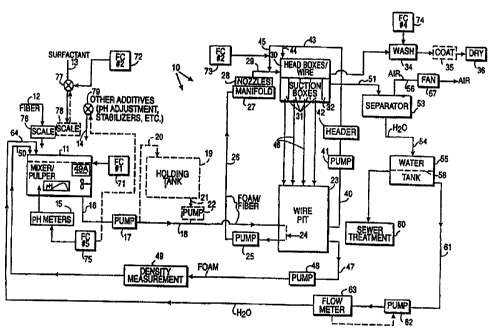
10 An exemplary system for making cellulose and synthetic fiber mats
or webs, according to the: foam process of the invention, is illustrated
schematically at 10 in FIGURE 1. The system includes a mixing tank or
pulper 11 having a fiber input 12, a surfactant input 13, and an input 14
for other additives, such as pH adjustment chemicals like calcium
carbonate or acids, stabilizers, etc. The particular nature of the fibers,
surfactant, and additives is not critical and they may be varied widely
depending upon the exact details of the product being produced
(including ifs basis weight). It is desirable to use a surfactant that can be
fairly readily washed out since a surfactant reduces the surface tension of
the final web if it is still present, and particularly for the Weyerhaeuser
proprietary products mentioned below that is an undesirable feature.
The tank 11 is per se entirely conventional, being the same type of
tank that is used as a pulper in conventional paper making systems using
the water-laid process. The only differences are that the side walls of the
mixer/pulper 11 are extended upwardly about three times the height in the
water-laid process since i:he foam has a density about a third that of
CA 02336616 2001-O1-04
WO 00/01882 PCT/FI99/00579
11
water. The rpm and blade configuration of the conventional mechanical
mixer in the tank 11 is varied depending upon the particular properties of
the product being produced, but is not particularly critical, and a wide
variety of different components and variables may be employed. Brakers
may also be provided o~n the walls. There is a vortex at the bottom of the
tank 11 from which the foam drains, but the vortex is not visible once start
up occurs because the tank 11 is filled with foam and fiber.
The tank 11 also preferably includes therein a large number of pH
meters 15 for measuring the pH at a number of different points. pH
affects surface tension, and thus needs to be accurately known. The pH
meters 15 are calibrated daily.
At initial start up, water is added with the fiber from line 12, the
surfactant from line 13, and other additives in line 14; however, once
operation commences no additional water is necessary and there is
mainly foam maintenance in the tank 11, not only foam generation.
The foam exits the bottom of the tank 11, in a vortex, into line 16
under the influence of the pump 17. The pump 17, like alt other pumps in
the system 10, preferably is a degassing centrifugal pump. The foam
discharged from the pump 7 passes in line 18 to further components.
FIGURE 1 illustrates an optional holding or buffer tank 19 in dotted
line. The holding or buffer tank 19 is not necessary but may be desirable
to ensure a relatively even distribution of the fiber in the foam in case
there is some variation I:hat is introduced into the mixer 11. That is, the
holding tank 19 (which is small, typically only on the order of five cubic
meters) acts more or less like a "surge tank" for evening out fiber
distribution. Because the total time from mixer 11 to the headbox is
typically only about 45 seconds in the practice of the process of the
CA 02336616 2001-O1-04
WO 00/01882 PCT/FI99/00579
12
invention, the holding tank 19 -- used -- provides time for variations to
even out.
When the holding tank 19 is used foam is fed from the pump 17 in
line 20 to the top of the 9:ank 19, and exits the bottom of the tank in line
21
under the influence of a pump, preferably centrifugal pump 22, then
leading to line 18. That is, when the holding tank 19 is used the pump 17
is not directly connected to the line 18, but only through the tank 19.
The line 18 extends to the wire pit 23. The wire pit 23 is per se a
conventional tank, again the same as in the conventional water-laid paper
process system, but with higher side walls. It is important to make the
wire pit 23 so that there .are no dead corners and therefore the tank 23
should not be too large. The conventional structure 24 which allows the
foam and fiber mixture in line 18 to be introduced into the pump 25 (which
is operatively connected adjacent the bottom of the wire pit 23) will be
described further with reaped to FIGURE 2. In any event, the pump 25
pumps the foam/fiber mixture in line 18, introduced by mechanism 24,
and additional foam from the wire pit 23, into the line 26. Because a fairly
large amount of foam is .drawn into the pump 25 from the wire pit 23,
typically the consistency in line 26 is significantly less than that in line
18.
The consistency in line 18 is typically between 2-5% solids (fibers), while
that in line 26 is typically between about 0.5-2.5%.
In the wire pit 23 there a no significant separation of the foam into
layers of different density. While there is a minimal increase toward the
bottom, that degree of increase is usually small and does not affect
operation of the system.
From the line 26 the foam/fiber passes to the manifold 27 which
has foam generating no~:zles 28 associated therewith. Preferably the
nozzles 28 -- which are conventional foam generating nozzles (which
CA 02336616 2001-O1-04
WO 00/01882 PCT/FI99/00579
13
agitate the foam greatly) as used in the patents 3,716,449 and 3,871,952
-- are mounted on the manifold 27, and a large number of the nozzles 28
are mounted on the manifold 27. Extending from each nozzle 28 is a
conduit 29 which leads to the headbox 30 of the former, through which
former a conventional paper malting wire or wires (foraminous elements)
passes or pass.
The headbox 30 has a plurality of suction boxes (typically about
three to five) 31 which withdraw foam from the opposite side of the wire
from the introduction of the foam/fiber mixture, and a final separation box
32 is at the discharge end of the formed web 33 from the headbox 30.
The number of suction boxes 31 provided in the suction table to control
drainage are increased for denser products, or for higher speed
operation. The formed web 33, which typically has a solids consistency of
about 40-60% (e.g. about 50%), is preferably subjected to a washing
action as indicated schematically by wash stage 34 in FIGURE 1. The
wash stage 34 is to remove the surfactant. The high consistency of the
web 33 means that a miinimum amount of drying equipment need be
utilized.
The web 33 passes from the washer 34 past one or more optional
coaters 35, to the conventional drying station 36. In the conventional
drying station 36 when synthetic sheath/core fibers (such as Cellbond)
are part of the web 33, the dryer 34 is operated tn raise the web
temperature above the melting point of the sheath material (typically
polypropylene) while the; core material (typically PET) does not melt. For
example where a Cellbond fiber is used in the web 33, the temperature in
the dryer is typically about 130°C or slightly more, which is at or
slightly
above the melting temperature of the sheath fiber, but well below the
approximately 250°C melting temperature of the core fiber. In that way
a
CA 02336616 2001-O1-04
WO 00/01882 PCT/FI99/00579
14
binding action is provided by the sheath material, but the integrity of the
product (provided by the core fiber) is not compromised.
While it is not always necessary, the process of the invention
contemplates the addition of pure foam to or immediately adjacent the
headbox 30 for a number of advantageous purposes. As seen in
FIGURE 1, the pump, preferably the centrifugal pump 41 draws foam
from the wire pit 23 into line 40. The foam in line 40 is pumped to a
header 42 which then distributes the foam to a large number of different
conduits 43, toward the headbox 30. The foam may be introduced -- as
indicated by line 44 -- directly underneath the roof of the headbox 30
(where it is an incline wire headbox), and/or via conduits 45 to the lines 29
(or nozzles 28) for introducing foamlfiber mixture into the headbox 30.
The details of the foam introduction will be described with respect to
FIGURES 3 through 6.
The suction boxe:> 31 discharge the foam withdrawn from the
headbox 30 in lines 46 into the wire pit 23. Typically no pumps are
necessary, or used, for that purpose.
A significant amount of the foam in the wire pit 23 is recirculated to
the pulper 11. The foam is withdrawn in line 47 by a pump, preferably
centrifugal pump 48, andl then passes in conduit 47 through the
conventional in-line density measurement device 49 for introduction - as
indicated schematically at 50 -- back into the tank 11. In addition to
providing density measurement for the foam in line 47 at 49, as
schematically illustrated iin FIGURE 1 one or more density measuring
units (such as denseomeaers) 49A may be mounted directly in the tank
11.
In addition to foam recycle, there is also typically water recycle.
The foam withdrawn from the last suction box 32 passes via line 51 to a
CA 02336616 2001-O1-04
WO 00/01882 PC'TJF199/00579
conventional separator .53, such as a cyclone separator. The separator
53 -- e.g. by vortex action -- separates air and water from the foam
introduced into the separator 53 to produce water with very little air in it.
The separated water passes in line 54 from the bottom of the separator
5 53 to the water tank 55. The air separated by the separator 53 passes in
line 56, with the assistance of the fan 57, from the top of the separator 53
and is discharged to atmosphere, or used in a combustion process or'
otherwise treated.
A liquid level 58 is established in the water tank 55, with some
10 liquid overflowing to sewer or treatment, as indicated schematically at 60
in FIGURE 1. Water is .also taken from below the level 58 in the tank 55
via line 61, and under the influence of a pump, preferably a centrifugal
pump 62 is pumped in line 61 through a conventional flow meter 63
(which controls the pump 62). Ultimately, the recycled water is introduced
15 - as indicated schematically at 64 in FIGURE 1 - to the top of the mixer
11.
Typical exemplary flow rates are 4000 liters per minute foam/fiber
in line 18, 40,000 liters per minute foamlfiber in line 26, 3500 liters per
minute foam in line 47, and 500 liters per minute foam in line 51.
The system 10 also includes a number of novel control
components. A first fuzzy controller, 71, controls the level of foam in the
tank 11. A second fuzzy controller 72 controls the addition -~f surfactant
in line 13. A third fuzzy controller 73 controls web formation in the
headbox 30 area. A fourth fuzzy controller 74 is used with the washer 34.
A fifth fuzzy controller 7;i controls the pH meters 15, and possibly controls
addition of other additivEa in line 14 to the mixer 11. Fuzzy control is also
used for surfactant and formation control. A multi-variable control
system, and a neural net control system (see FIGURE 18), also are
CA 02336616 2001-O1-04
WO 00!01882 PCT/FI99100579
16
preferably provided overlaying the other controls. The multi-variable
control also is used for c;ontrolling the efflux ratio at web formation. The
variables can be changE;d depending upon their effect on desired process
regulation, and end result.
In order to facilitate control of the various components, typically a
scale 76 is associated with the fiber introduction 12 in order to accurately
determine the amount of fiber being added, per unit time. A valve 77 in
line 13 may be provided for controlling the introduction of surfactant, as
well as a scale 78. A valve 79 may also be provided in the line 14.
The system 10 is believed unique among foam-laid systems
because essentially no valves are provided for intentionally contacting the
foam at any point during its handling, with the possible exception of
valves provided in lines ~46, which will be described with respect to
FIGURE 11.
Also, during the entire practice of the process of the system of
FIGURE 10 the foam is .kept under relatively high shear conditions. Since
the higher the shear the lower the viscosity, it is desirable to maintain the
foam at high shear. The foam/fiber mixture acts as a pseudo-plastic,
exhibiting non-Newtonian behavior.
The use of the fo<~m-laid process has a number of advantages
compared to the water-I<~id process particularly for highly absorbent
products. In addition tc~the reduced dryer capacity because of the high
consistency of the web 33, the foam process allows even distribution of
virtually any type of fiber or particle (without excessive "sinking" of high
density particles while low density particles do "sink" somewhat - they do
not sink at all in water) into the slurry (and ultimately the web) as long as
the fibers or particles have a specific gravity between about .15-13. T'he
foam process also allows the production of a wide variety of b«sis weight
CA 02336616 2001-O1-04
WO 00/01882 PCT/FI99/00579
17
webs, a product with increased uniformity and higher bulk compared to
water-laid process products, and a very high level of uniformity. A
plurality of headboxes may be provided in sequence, or two strata may be
made at the same time within a headbox with a double wire, and/or the
simple coaters 35 may be utilized to provide additional layers with great
simplicity (like coating).
Details of the components from the system of FIGURE 1, if
anything other than entirely conventional, are described with respect to
FIGURES 2 through 16.
FIGURE 2 show, the introduction of foam/fiber mixture, and foam,
to the pump 25 associated with the wire pit 23. The structure 24 is known
from the prior art Wiggins Teape process, and the foam/fiber p:3ssing in
line 18 is caused to be redirected as illustrated by the bent conduit 83 so
that from the open end 84 thereof the foamlfiber mixture is discharged
directly into the intake 85 of the pump 25. Foam from the wire pit 23 also
flows into the inlet 85, ass illustrated by arrows 86. Operation of pump 48,
done under fuzzy control; controls the level in wire pit 23.
Where the fibers to be used to make the foam are particularly long,
that is on the order of several inches, instead of directing the line 18 to
the suction inlet 85 of the pump 25 (as seen in FIGURE 2) the line 18
terminates in the line 26 downstream of the pump 25. In this case the
pump 17 must of course provide a higher pressure than it otherwise
would, that is sufficient pressure so that the flow from 18 is into the line
26
despite the pressure in line 26 from the pump 25.
FIGURE 3 illustrates the details of one form of the novel additional
foam introduction ,spec, of the Ahlstrom process. FIGURE 3 illustrates
foam per se from line 4.5 being introduced into the foamlfiber mixture in
the conduit 29 just prior' to the headbox 30. In other words, pure foam is
CA 02336616 2001-O1-04
WO 00/01882 PCT/F199/00579
18
added to the fiber/foarn mixture coming from the manifold 27 via nozzles
28. When foam injection lines 45 are utilized they need not inject foam
into all of the lines 29, just enough of them to achieve the desired results.
FIGURE 4 illusi:rates an exemplary incline wire former and its
headbox, 301, which utilizes two different forms of foam injection (the form
illustrated in FIGURE 3 plus another). In the headbox 301 of FIGURE 4
the inclined conventional forming wire 90 moves in the direction of the
arrow, and with foam injection at 45 the foam/fiber mixture is dispersed in
to the headbox 301 from the conduits 29 generally as illustrated in
FIGURE 4. Foam is also introduced into headbox 301 via conduit 44 so
that the foam flows generally as illustrated at arrow 92 in FIGURE 4. That
is the foam flowing in l:he direction of arrow 92 flows against the bottom of
the roof 93 of the headbox 301. A baffle 94 may be provided in the
headbox 301 to ensure the initial flow of the foam in the direction 92 from
each of a plurality of the conduits 44.
The foam introduced in conduit 44 is for the purpose of providing
less shear of fibers in 'the headbox 301 preventing the shear between the
fibers and the roof 93 ~of the headbox 301 from turning the fibers.
unidirectional, i.e. in the direction of the movement of the wire 90. Under
basic fluid dynamic principles, if the foam/fiber mixture is against the roof
93 there will be disturtaance at the boundary layer of the fiber orientation,
which is undesirable. The foam introduced to flow in the direction 92
eliminates that boundary layer problem. Also the foam introduced in line
44 flowing in direction 92 keeps the bottom of the roof 93 clean, which is
also desirable.
The introduction of the foam in conduits 45 (typically at an angle of
between about 30-90°), as illustrated in both FIGURES 3 and 4, is for a
different purpose. FIGURE 5 is a schematic top view (showing only three
CA 02336616 2001-O1-04
WO 00/01882 PCT/F199100579
19
conduits 29, whereas normally very many are provided) of the headbox
30 (e.g. 301) showing the difference pure foam injection makes. Without
the injection of the substantially fiber-free foam at 45 the foam/fiber
mixture introduced by conduits 29 is distributed generally as indicated by
lines 91 in FIGURES 4 and 5. However when there is foam injection at
45, the basis weight profile is changed because there is a greater
dispersion of the foam fiber mixture, as schematically indicated by fines
96 in FIGURE 5. The effect on the basis weight profile is seen in the
schematic illustration in FIGURE 6. The normal basis weight profile
{when there is no foam injection), illustrated by line 91A, includes a large
bulge 97. However when there is foam injection, as indicated by line 96a
the bulge 98 is much smaller. That is the basis weight is more uniform.
Profile control is effected by diluting foam at the manifold main flow, just
before or just after the tubes 29 (just before being seen at 45 in.Figure 4).
If desired the tubers 29 can lead the foam from the foam nozzles 28
to an explosion chamber in the headboxes 301, 30V. However there is no
real reason to use an explosion chamber in the headboxes for practicing
the Ahlstrom process. If used, an explosion chamber is solely for
security.
FIGURE 7 illustrates an alternative configuration of headbox that
may be utilized in the system 10. The entire former as well as the
headbox 30V have features in common with a conventional water-laid
process dual forming wire; vertical former and headbox, and includes the
forming wires 90, 90A. In the exemplary embodiment illustrated in
FIGURE 7 a suction roller 100 is shown at the discharge end of the
former, and rollers 101, 101A are provided for guiding the wires 90, 90A.
In one embodiment the wire 90A may also be guided by the suction roller
100 as indicated in dotted line, although in normal operation the wire 90A
CA 02336616 2001-O1-04
WO 00/01882 PCT/FI99/00579
travels over the top roller 101 along with the web 33 after discharge.
Suction tables are less expensive than suction rollers, and are preferred,
although suction rollers may be utilized such as indicated at 100 in
FIGURE 7.
5 The headbox 30V includes a bottom 102 and side walls 103, 104.
Defined between the side walls 103, 104, and a central wall structure 110
are the foam/fiber volumes 105, 106. While the same foam/fiber mixtures
may be introduced into the volumes 105, 106, typically they are entirely
different mixtures which form two distinct strata in the web 33. One foam
10 fiber mixture is introducE:d from manifold 27 through nozzles 28 for
example via line 29 through the bottom 102 of the headbox 30V as
indicated by inlet 107, while the other foam/fiber mixture comes from
manifold 27A, passing through nozzles 28A and being introduced into
inlet 107A in the bottom 102 of the headbox 30V. Alternatively, or in
15 addition, the foam/fiber mixtures may flow in the conduits 29' and 29'A
through the inlets 108, 108A, respectively, in the side walls 103, 104,
respectively. In any event the introduced foamlfiber mixture flows
upwardly in the chambers 105, 106 into contact with the wires 90, 90A,
with suction being appliE:d by the conventional suction boxes 31, 31A.
20 The wall structure: 110 in the headbox 30V is illustrated also in
FIGURE 8. The wall structure 110 is used not only to separate the
volumes 105, 1.06 but also to introduce additional materials into the
suspension so that the materials do not come into direct contact with the
wires 90, 90A. This is important for some materials, such as SAPs
(Super Absorbent Products), will foul the wires 90, 90A if they contact
them. By providing introduction utilizing the wall structure 110, the
introduced materials (such as SAPs) are provided just prior to actual web
CA 02336616 2001-O1-04
WO 00/01882 PCT/FI99/00579
21
formation, and do not have a chance to contact the wires 90, 90A, or
otherwise interfere with the processing.
With particular regard to FIGURE 8, the interior of the structure 110
includes a plurality of conduits 113 through which additive material -- such
as a SAP from source 111 at a solids consistency of about 10-20% -
flows upwardly until it is discharged through the enlarged triangular
shaped end 114 of the conduit 113. Between the tubes 113 with their
flared end terminations 114 may be provided plates 115 which hold the
tubes 113 in position. Plates 116 (see FIGURES 7 and 8) are provided
on the opposite sides oi' the tubes 113 to define a pathway for the
foam/fiber mixture in thE: chambers 105, 106. The SAP, or other material,
is discharged as indicated at 117 in FIGURE 8, at a point past at least the
first suction box 31, 31A, and substantially into the center of the
foam/fiber mixture at that point, so that there is almost no possibility that
the material discharged at 117 will directly contact the wires 90, 90A.
The conduits 113 are preferably circular in cross-section, while the
flared ends 114 have flat sides, and a substantially rectangular.opening
configuration where the material 117 is discharged. The flared ends 114
extend over substantially the entire top of the structure 116, as seen in
FIGURE 8.
The product produced utilizing the headbox 30V typically has two
or more different strata which are integrally provided together in the web
33, and where the material 117 is introduced it is introduced so that it is
essentially between the strata, and extending partially into each strata.
FIGURE 9 shows., as a sectional view perpendicular to the
machine direction an exemplary construction of a suction box 31 of the
former or headbox 30 that is presently (and has been for years) used in
glass tissue manufacture, and which also likely will be employed in the
CA 02336616 2001-O1-04
WO 00/01882 PCT/FI99/00579
22
manufacture of the webs 33 according to the Ahlstrom process. As can
be seen in FIGURE 9, i:he forming wire 90 extends over the toy of the
suction box 31, which bias side walls 118. Openings or tubes 119 are
provided in the side walls 118 to allow air to flow into the suction box 31
beneath the wire 90, in addition to the foam 120 pulled from the
foamlfiber mixture that is on the opposite side of the wire 90 from the
walls 118. The air freelly moves through the tubes 119 as a result of the
suction that exists in the suction box 31, provided in the conventional
manner. However, the tubes 119 are provided with valves the opening of
which is automatically, or at least manually, controllable. The foam then
passes through the conduit 46 to the wire pit 23. Since air has been
introduced through the conduits 119, however, it is desirable to remove
the excess air that has been introduced (but not to significantly change
the airlliquid ratio of thE: foam from what it was in the foam/fiber mixture).
To this end a conduit 121 is connected to the conduit 46, and a fan 122
exhausts air through the conduit 121.
FIGURE 10 is a schematic representation of the vertical former
including headbox 30V of FIGURE 7 shown in association with the other
components of the fornner, including a wide variety of rollers that are used
for guiding and/or powE:ring the wires 90, 90A, as well as a washing
section 34 and a dryer 36. The particular features of FIGURE 10 that are
of significance are the provision of the conduits 124 which lead to
collectors 125, which are in turn connected to the conduits 46. The
conduits 124 are connE~cted to both the suction boxes 31, 31A. FIGURE
11 schematically illustrates the connection of a plurality of the conduits
124 to a collector 125, and the connection of the collectors 125 to the wire
pit 23.
CA 02336616 2001-O1-04
WO 00/01882 PCT/F199/00579
23
FIGURE 11 shows one way in which the foam level 128 in the
collectors 125 may be controlled. A remotely actuated (e.g. solenoid)
valve 127 is provided in each of the conduits 46 extending from a
collector 125 toward wire pit 23, controlled by controller 129. If the valve
127 is closed, or partially closed, foam can back up into the collector 125
as illustrated in FIGURE. 11. This allows the level 128 in the collector 125
to be controlled. When the valves 127 are completely open the foam
freely flows through the conduits 46 into the wire pit 23 below the level of
the foam therein.
In all of the embodiments of the system 10 it is preferred that there
be no pumps provided in conduit 46 for withdrawing the foam; rather the
foam merely flows freely under the force of gravity to the wire pit 23.
FIGURE 12 schematically illustrates wash and coater stations
which may be provided in the system 10. Wash liquid is introduced
through the wash box 3~4 at the top of the web 33, and suction is applied
to the bottom 130 via the fan 131 to remove the wash liquid after it has
passed through the web, primarily removing the surfactant from the web
33. The wash box 34 may be of any conventional construction, such as
used at the present timE; to remove binder (using chemicals instead of
water) in the Ahlstrom glass tissue manufacturing process.
The process of the invention allows additional layers to be readily
applied to the web 33 without requiring additional headboxes. While
other headboxes may b~e used for that purpose, it is much simpler to use
one or more coaters 35 downstream of the washer 34 to apply different
materials, such as indic;3ted by the layer 132 applied by the simple coater
35. The simple coater 35 is an entirely conventional piece of equipment
that lays down a layer 132 of desired thickness of any other material
(which could include another fiber mixture) on top of the web 33.
CA 02336616 2001-O1-04
WO 00/01882 PCT/F199/00579
24
Downstream of the coai:er 35, i.e. after the layer 132 has been applied, a
dewatering device 133 is provided which comes into contact with the layer
132 to dewater it.
As is conventional a perforated belt or forming wire 134 'guided by
the rollers 135 moves in the same direction as the web 33 past the
suction box 136. The box 136 withdraws the excess fluid from the layer
132 while the web 33 is supported at the bottom by conventional rollers
137, a conveyor belt, etc. It is important that the suction box 136 be on
the opposite side of the layer 132 from the web 33 in order to properly
remove the excess fluid. The belt 134 and rollers 137 (or other belt)
provide a nip which assists in dewatering the layer 132.
After the dewatering station 133 it is desirable to use, as part of the
conventional dryer 36, a blower 139 to blow air through the layer 132/web
33 from the top, which Exits through the conduit 140, which may
connected to a suction ource to assist the air movement from the blower
139. The dryer 36 may also have other features, as is conventional.
Any number of c~oaters 35, 35' may be provided, with either a
dewatering station 133 associated with each coater 35, 35', or a number
of coaters provided before the dewatering station 133, depending upon
the particular layers being coated onto the web 33.
FIGURES 13 through 16 indicate the various inputs that are
provided to the fuzzy controllers 71 through 74 in order to provide precise
control of the system 10, and FIGURE 17 shows the relationship of the
fuzzy controls to other controls. This precise control of the system 10 is a
major factor that allows the process of the invention to succeed where
others have failed in thc: production of commercial cellulose and synthetic
fiber webs, and enhanced production of glass or aramid fiber webs.
CA 02336616 2001-O1-04
WO 00/01882 PCT/F199/00579
As illustrated in FIGURE 13, the fuzzy controller 71 controls the
level of foam in the mixerlpulper 11. The inputs to the fuzzy controller 71
comprise the foam den:;ity (from either the in-line denseometer 49 or the
denseometer 49A in they mixer/pulper 11, but not both), the pH measured
5 by the pH meters 15, the flow rate of recycled foam in line 47, as
determined by the rpm of the centrifugal pump 48 (measured by
conventional means), the level 128 of the wire pit 23, and the fiber flow
from line 12 into the mix:er/pulper 11, or other flow variables. The fiber
flow in line 12 is accurately determined utilizing the scale 76 which
10 measures the amount of fiber per unit time being added to the pulper 11.
FIGURE 14 shows the inputs to the second fuzzy controller 72
which is used to control the valve 77, and/or the dumping of a scale 78, or
other mechanism which controls the addition of surfactant to the pulper
11. The inputs to the fuzzy controller 72 are the surfactant flow rate, such
15 as determined by the scale 78, the pressure in the manifold 27 (which
typically is between 1-1..8 bar, depending upon the product produced), the
level 128 of foam in the wire pit 23, the pH as determined by the pH
meters 15, the fiber flow rate, as determined by the scale 76, and the flow
rate of recycled water in line 61, as determined by the flow meter 63.
20 FIGURE 15 illustrates the inputs to the third fuzzy controller 73,
which is used to control the aiNfoam ratio for formation of the web in the
headbox 30 (such as controlling the wire speed or the pressure in the
former headbox). Inputs to the third fuzzy controller 73 include the
headbox 30 pressure, the level 128 of foam in the wire pit 23, the volume
25 of foam removed from the headbox with suction boxes 31, the foam
density as measured by the denseometers 49 or 49A, the web 33 basis
weight (after the web formation, or after the dryer 36), and the level of
CA 02336616 2001-O1-04
WO 00/01882 PCT/FI99/00579
26
suction at each suction box 31 (or 31A). The headbox 30 pressure is
controlled by controlling the rpms of the pump 25.
FIGURE 16 shows the inputs for the fourth fuzzy controller 74,
which controls the washer 34, namely the wash liquid flow rate and the
suction. The inputs to the fourth fuzzy controller 74 include the web 33
basis weight, the suction fan 131 speed, the pressure at the washer 34,
the wash liquid temperature, and the speed of web formation (the speed
of the wires 90, 90A).
In the short transit time (about 45 seconds) from the pulper 11 to
the headbox 30 the fo;am/pulp mixture is preferably kept in a high level of
agitation/shear. The shear is primarily controlled by the level of foam in
the pulper 11, where tlhe foam is agitated by the conventional rotating
blade; the pressure drop over the foam generation nozzles 28; the
headbox 30 location (position); primary drainage control such as by
controlling the vacuum for the slots for both the vertical and the incline
headboxes 30V, 301; and by the speed of the centrifugal pumps 17, 25,
and 48. Except for thE~ valves 127 in FIGURE 11 (if utilized) the entire
system 11 is valveles:>, and there are no valves used to intentionally
contact the foam. ThE: recycle pump 48 amperage and rpm are
measured, as is the pressure drop across the nozzles 28. If the
amperage of the recycle pump 25 changes while the density (as
measured at 49) is the: same, then the bubble size distribution has ..
changed. It is then necessary to change the surfactant addition (either by
adding more surfactant or reducing the amount added) through line 13 to
return the bubble size to the desired distribution.
A multi-variablE: controller gives the computer set points to all of the
fuzzy controllers 72 through 75, as seen in FIGURE 17, and neural net
control 145 of FIGURE 17 takes data from quality measurements and
CA 02336616 2001-O1-04
WO 00/01882 PCT/FI99/00579
27
process parameters 14!3 and provides long term regulations and
predictions, and set points.
FIGURE 17 shoves, schematically, a conventional neural net
control 145 operative connected to provide and receive data and controls
to and from a conventional multi-variable control 146 and fuzzy logic
controls 147, 148. Quality parameters from laboratory testing at 149
(which typically are cornducted off line -- such as for foam stability) are
input the neural net control 145 so that set points for long term regulation
and prediction may be provided. An example of one of such
measurements is foam stability, discussed hereinafter.
The foam must remain stable and substantially uniform throughout
the entire process. Foam stability is measured in a simple test, typically
conducted off line. A liter container having graduation marks along the
side is filled with foam up to the top, and any foam extending above the
top of the container scraped off. As soon as the foam is placed in the
container a timer is started. The net weight of the foam in the container is
measured (in grams), and that is divided by two. The timer continues to
run until enough water drains from the foam to reach the level (in
milliliters) along the graduations on the container corresponding to the
weight of the foam divided by two. (In doing this test the assumption is
made that all the weighl: is due to the water, that is that the air has zero
weight.) As an example:, the one liter of foam might weigh 320 grams.
320 divided by two is 180. Once the water level in the container reaches
160 milliliters, the timer is stopped. The optimum stability of th:; foam is
when it takes approximately seven minutes for half the water to drain. If
the time of the test is outside of the range of 4-10 minutes, the foam does
not have acceptable stability.
CA 02336616 2001-O1-04
WO 00/01882 PCT/FI99/00579
28
The foam-laid process of the invention is practiced utilizing the
parameters in the following Table I. While a number of these parameters,
such as the pH and manifold pressure, are product dependent, the values
given are the initial values proposed for making two Weyerhaeuser
proprietary products known as Unitary Stratified Composite (USC) and
Reticulated Storage Core: (RSC). These proprietary products of
Weyerhaeuser are combinations of synthetic and cellulosic fibers. Other
parameters may be used for glass web production.
TABLE 1
Example of typical foamlprocess parameters
(The range of parameters can be wider if the product range is
wider)
PARAM ETER VALU E
pH (substantially entire About 6.5
system)
temperature About 20-40°C
manifold pressure 1-1.8 bar
consistency in mixer 2.5%
consistency in headbox.5-2.5%
SAP additive consistencyAbout 10-20%
consistency of formed About 40-60%
web
web basis weight variationsLess than %Z%
foam density 250-450 grams per liter
at 1 bar
foam bubble size .3-.5 mm average diameter
(a
Gaussian distribution
CA 02336616 2001-O1-04
WO 00/01882 PCT/FI99/00579
29
foam air content 25-75% (changes with
pressure in the process)
viscosity there is no "target" viscosity,
but typically the foam has viscosity on
the order of 2-5 centipoises under
high shear conditions, and
200 k - 300 k centipoises at low shear
conditions
web formation speed initially about 200 meters per
minute, target 500 m/min.
specific gravity of fibers or anywhere in the range of .15-
additives 13
surfactant concentrationdepends on many factors,
such as water hardness,
pH, type of
fibers, etc. Normally between
0.1-
0.3% of water in circulation
forming wire tension between 2-10 N/cm
exemplary flow ~rafe
- mixer to wire pit 4000 liters per minute
- wire pit to headbox 40,000 liters per minute
- foam recycle conduit 3500 liters per minute
-- suction withdrawal 500 liters per minute
to water
recycle
CA 02336616 2001-O1-04
WO 00/01882 PCT/FI99/00579
In a complete, complex system according to the invention (e.g. for
production of glass fiber non-woven webs) items that may be controlled
by fuzzy logic control (aindlor multivariable, andlor neural net control),
5 include:
- Total basis weight (having as input parameters at least some
(e.g. two) of, and preferably all of, fiber mass flow, fiber mass moisture,
binder suction, binder flow, suction before binder feeding, binder content,
binder viscosity, binder pH, binder temperature; and machine speed).
10 -- Binder tank level (having as input parameters at least some (e.g.
two) of, and preferably all of, binder feeding, binder formulation, binder
dry content, suction before binder feeding, wire speed, binder pH, and
binder air content). Binder can also be provided and controlled at the
washing and chemical addition stages.
15 - Wire pit (23) level (having as input parameters at least some
(e.g. two) of, and preferably all of, level control pump, suction in suction
boxes (formation), run pump (rpm), run pump energy, manifold pressure,
head box pressure, suction tube flows, and foam density).
- Mixing tank (11) level (having as input parameters at least some
20 (e.g. two) of, and preferably all of, manifold pressure, foam density in
the
mixing tank, pH of foann, foam back feed from the wire pit or short
circulation, feed of surfactant, water back flow, foam density o' the short
circulation, mass feed, level of the buffer tank, level of wire pit, agitator
energy, and foam temperature).
25 -- Manifold (27) pressure (having as input parameters at least
some (e.g. two) of, and preferably all of, pump (25) rpm, manifold outlet
valve, former suction pressure, foam density, foam stability, surfactant
feed, mixing tank level, buffer tank level, wire pit level, foam pH, mass
CA 02336616 2001-O1-04
WO 00/01882 PCT/FI99/00579
31
feed, water back flow, mixing tank density, wire shower pressure, wire
water control suction, suction of dry suction box, suction of former outlet,
overflow from former, and foam temperature).
- Foam density (having as input parameters at least some (e.g.
two) of, and preferably all of, surfactant feed, all tank levels, temperature,
pH, water back flow, mass feed, wire water control suction, manifold
pressure, line speed, and pump and blender energy).
-- Efflux ratio (having as input parameters at least some (e.g. fiwo)
of, and preferably all of, manifold pressure, foam density, head box
pressure, all former suctions, mass feed, wire pit level, wire speed,
temperature, and former overflow).
-- Surfactant feed (having as input parameters at least some (e.g.
two) of, and preferably .all of, foam density, foam temperature, fiber mass
feed, and foam stability).
The fuzzy controllers, neural net control, and multi-variable controls
utilized according to the' invention are all conventional off the shelf items,
such as available from Honeywell-Alcont.
The MultivariablE: Control typically measures the web profile and
controls the dilution in or to separate distribution tubes, and gives the set
point to variable fuzzy controls. The Neural Net Control takes data from
the quality measurements and process data and gives set points for long
term regulation and prediction. All of the variables can be changed
depending on which of them has more weight to effect proper regulation,
and are most important for the end product production.
FIGURE 18 illustrates, schematically, various interrelationships
between control components according to the invention, using the neural
net 145 (which receives the lab values as from 149 in FIGURE 17). 'There
are three different segments controlled by the neural net 145, the
CA 02336616 2001-O1-04
WO 00/01882 PCT/FI991005'79
32
formation part of the web, illustrated schematically at 150 in FIGURE 18,
the binder system 151 (typically used only when the majority of the fibers
to make up the web are glass or aramid fibers or the like), and the drying
system 152. There arE: three basic subsystems connected to the neural
net 145, an optimization control 153, the horizontal multi-variable
predictive control (HMf'C) 154 (a conventional multi-variable type
controller), and the statistical process control (SPC) 155. The former
control is indicated schematically at 156 with all the various inputs and
self controls associated therewith schematically illustrated below the
reference numeral 15E~ in FIGURE 18. Similarly, for the binder 157 and
the dryer 158.
That is on the first level control of the foam process of the invention
is a neural net model 145 that is active in the quality control of
substantially the wholE; production process. Any of the versions 1-3 of
Model-CC, PROP (proportion)-algorithm model, evolution algorithm
(ENZO) or a combination of the above can be used as the core, teaching
algorithm, prediction code, simulation code and optimization code of the
neural net model 145. Also newer versions of the above as well as totally
new cores, teaching algorithms, prediction codes, simulation codes and
optimization codes of the neural net model can be used. _
The INPUTs of the neural net model are the quality parameters of
the process, such as basis weight, glass weight, binder percentage,
thickness, porosity, tear strength, strength, fiber orientation, high
temperature tensile strength, oil porosity, opacity, wet tensile strength,
foam stability, etc. from off line measurement (e.g. 149 in FIGURE 17), or
on-line determination:..
The OUTPUTs of the model 145 are the control or set values of the
process parameters. These include, among other things, fiber feed 145,
CA 02336616 2001-O1-04
WO 00/01882 PCT/FI99/00579
33
manifold (27) pressure, puiper (11 ) level, buffer tank (19) level,
circulation
pressure (e.g. pumps 25, 48 and/or 62), and formation (31) suction.
During test runs, a combination of evolution algorithm (ENZO) and
PROP yielded, with respect to basis weight, with a confidence level of
95%, a result of <1.4 g/rn2.
The machine direction profile or the cross direction profile of the
final web 33 from the production process can be controlled by means of
either an HMPC (Horizon Multivariable Predictive Control) controller 154,
based on ON-L1NE measurements, or a predictive multivariable controller.
These controls can also be used for controlling any other part of the
process, the control problems of which are too complex for conventional
control methods (PID controller).
The HMPC control 154 is desirably used for controlling the web 33
profile in the machine direction. The control unit for the machine direction
comprises a model-based, predictive multivariable algorithm. The~HMPC
controller 154 is a multi-inputlmulti-output matrix type control algorithm,
and it is used for predicting the steadying state of the process by means
of a certain process model. The HMPC controller 154 also takes into
consideration the limiting states of the actuators and the optimization
functions of adjustable variables.
The multivariablE: control unit (HMPC 154) considers the interaction
between variables to bf: controlled (measurable variables to be
maintained at their set values, such as basis weight, speed, and humidity)
and the process variablles (actuator variables, such as speed and pulp
flow). Table II shows the control matrix model of a machine directional
HMPC control.
CA 02336616 2001-O1-04
WO 00/01882 PCT/F199/00579
34
TABLE II
Control matrix model of a machine directional HMPC control
Filler feed Binder suction Speed
Amount of glass
Amount of binder
Speed
The control 154 adjusts multiple outputs simultaneously and
maintains the controlled variables at desired values. The HMPC
controller 154 also considers disturbance variables. Such disturbance
variables are taken into consideration, for instance, when the machine
(whole process) is started or when the grade is changed (for example the
basis weight is changed). They are measurable variables that have an
influence on the controlled variables but are not controlled by the control
154. Disturbance variables can also be used for feed-forward control.
The control 154 predicts, how disturbance variables affect the controllable
variables. The predictions are then used for effecting the necessary
corrections to the outputs of the control 154.
One of the advantages of the control unit 154 is the prediction for
the steadying state of the process. These prediction values inform the
user in more detail about the future situation. The final situation of the
control will also be displayed to the user. The HMPC controller 154 is
also able to predict the point at which the control is driven to the
operational constraint of the actuator and is able to adjust the control
strategy according to the: situation. Predictability enables weighted
factors to be set for the control, so that function prioritization is used for
CA 02336616 2001-O1-04
WO 00/01882 PCT/F199/00579
optimizing the state of the machine. For example, the control can
automatically lower the aet value of basis weight, if binder percentage
needs to be increased for increased thickness and the basis weight is
already on the upper constraint of operation.
5 In one example o~f the foam process of the invention, the control in
machine direction utilizes a 3 x 3 matrix. However, depending upon the
number of variables, it is alsa possible to use other types of matrices, for
instance, a 10 x 10 matrix (10 inputs and 10 outputs). The controllable
variables are amount of glass (or other fber), amount of binder (if used),
10 and speed. Actuator variables are fiber feed, binder suction, and speed.
In test runs, it has been possible to decrease the basis weight, glass
weight and binder percentage scatter by 50% in machine direction, by
using the controls according to the invention in the manufacture of glass
webs.
15 The purpose of optimization control (153 in FIGURE 18) is to
minimize costs, to maxirnize yield, or to eliminate a production bottleneck
in a part of the process. An example of optimization is interactively
optimizing the material flow, chemical feed, energy consumption,
production quality goals" and production capacity for each case. The best
20 possible way of running the process has been established by means of
optimization of the process according to both the set goal and the process
constraints.
An SPC (Statistical process control method) 155 may also
optionally be employed.
25 Process control is performed by using fuzzy logic neural nets, PID
controllers, or a combination thereof. That is, the foam process of the
invention utilizes fuzzy logic, neural nets, PID controllers, or a
combination thereof for controlling the former section 156, the binder
CA 02336616 2001-O1-04
WO 00/01882 PCT/FI99100579
36
section 157, and the dryer section 158 of the process. In the former
section 156, the procesa can be controlled by using fuzzy logic, neural
nets, PID controllers or a combination. The following items can be
controlled in the former section 156: foam density in the wire pit 23,
pulper 11 foam density, fiber orientation, pulper 11 level, wire pit 23 level,
headbox 27 pressure, height of the slice opening of the headbox 30 (the
thickness of the web at the headbox 30 exit), glass weight (mass flow
weight of the glass or other fiber -- 12, 76 in FIGURE 1), pH, buffer tank
19 level, surfactant flow 13, formation profile (the suction or drainage
profile, using 31, 32), speed of the wire 30, the basis weight of the fiber
feed (kg/min. -- mass flow), suction box 31 pressure, manifold 27
pressure, total suction of formation sections (flow, suction levels, suction
box 31 pressure, etc.), trailing edge suction (after web formation), dry
suction (after high pressure suction), change of formation suction
difference variable (dP for upper side - lower side), thickness of the web
33, and porosity of the web 33.
In further explanation of some of the parameters set forth above,
fiber orientation can be considered to correspond to the strength ratio, i.e.
the strength of the web 33 in the machine direction versus the strength
thereof in the cross machine direction. This is controlled by the wire 30
velocity, flow into the headbox 30, pressure, foam density, and profile of
the suction from the suction boxes 31. Pressure at the pump, the
drainage time of the foam, the density of the foam, the pH, and other
factors also may play a part. Ultimately, the efflux ratio is calculated,
which is the velocity of the foam compared to the velocity of the wire. The
velocity of the wire is normally held constant for any particular process.
Control is provided at each suction box 31, 32 position.
CA 02336616 2001-O1-04
WO 00/01882 PCT/FI99/00579
37
The trailing edge suction which is after web formation and the
normal suction boxes 3'1, is a pressure that is higher than the suction box
pressure. This sucks air with the foam, as indicated at 32 in FIGURE 1,
which utilizes the separator 53 for the air.
The dry suction is typically after, e.g. liquid ring vacuum pumps,
such as Nash pumps, or other high pressure suction devices. This is
typically water removal that is effected just before drying (see 36 in
FIGURE 1).
The binder section 157 of the process can be controlled by using
fuzzy control, neural net, PID control or a combination of these. At least
the following items can be controlled: binder percentage in the web 33
(binder formation suction, after the binder additive controls control the
addition of binder at 157), pH of the binder, basis weight and binder
formation suction, binder circulation tank level, binder temperature, and
suction speed.
The dryer section 158 of the process can be controlled by using a
fuzzy controller, neural net, PID control or a combination thereof. At least
the following items can be controlled: drying temperature at various
points along the dryer, web 33 speed, energy fed to the dryer 36,
moisture in the dryer, and the pressure difference (above and below the
web 33 at different points along the dryer).
An example of the use of fuzzy logic in accordance with the
present invention for foam density control is seen in FIGURES 19 and 20.
FIGURE 19 showy the foam density controller 160 schematically
connected to fuzzy control 161, and process 162. The foam density set
point is input to the controller 160, while other parameters are input to the
fuzzy controller 161 and the process 162, which ultimately provide the
measured density of the foam. The set point minus the measured density
CA 02336616 2001-O1-04
WO 00!01882 PCT/FI99/00579
38
is the difference betweE:n them. This data is utilized as illustrated in the
foam density schematic: control diagram of FIGURE 21.
As illustrated in f=IGURE 20, various inputs 163 are provided at
fuzzification 164, which applies the rule base 165, which provides the
defuzzification output 166 to control the process metering. The
operations 164-166 together provide the conventional fuzzy controller
167. Inputs provided at 163 desirably include the foam density
measurement, such as from 49, the holding tank 19 overflow, the foam
pH (as measured by pHl meters 15 for example), the fiber feed (as at 12,
76 in FIGURE 1 ), the foam temperature, the density of the foam in the
pulper 11, the differencE: between the foam density set point and the
measured density, return water flow, foam viscosity, fiber quality, the
drainage time of the foam (determined by the test as described above),
the water quality (such <~s pressure and hardness), the suction after
cleaning of the wire (suc;king out water from the wire), the surfactant
chemistry (the Z potential) which can be dependent upon the surfactant,
its pH, the particular fibers used, and water hardness among others, and
the surfactant feed rate (13, 77, 78 in FIGURE 1).
The pulper 11 foam density (static pressure + level), or short
circulation density (from 49), value is used as the actual value for the
fuzzy controller (164-16Ei). In this example, short circulation density (from
49), has been used as the actual value. Pulper~density is used as a
reference value, and the change of its difference variable, compared to
the foam density, is used as one of the INPUT 163 values of the control.
The input and disturbance variables of a fuzzy control can be
improved with SPC or a neural net or a PID control. In this case, either
the value of the process measurement is set as a constant by using a PID
control, or the input value is improved by using a neural net as an input.
CA 02336616 2001-O1-04
WO 00/01882 PCT/FI99/00579
39
In the first stage the inputs of a fuzzy control are fuzzified164.
Fuzzification can take place in either three or five stages. In fuzzification,
the numeric value of a variable is transformed into membership of a set,
i.e. a non-dimensional comparable value. In the example, the application
has been carried out so i:hat it is easy to move from three-stage
fuzzification to five-stage fuzzification, or vice versa. FIGURE 21
illustrates the principle of fuzzifying a process measurement into
memberships in five fuzzy groups. Fuzzification 164 is defined by
membership level functions that indicate the membership of each fuzzy
set as a function of the numeric value of the variable.
FIGURE 22 schematically illustrates the fuzzification of foam
density process increment values, e.g. the membership level functions of
foam density measurement.
VE is the difference variable of the foam density i.e. VE = SET ~-
MET (set point minus measured value, from FIGURE 19). The
membership level outputs are:
BPO is big positive
POS is positive
ZER is zero
NEG is negative
BNE is big negatiwe
The t~!.ning variables for regulating are:
FBPO is the tuning variable for group BPO
FPOS is the tuning variable for group POS
FZER is the tuning variable for group ZER
FNEG is the tuning variable for group NEG
FBNE is the tuning variable for group BNE
CA 02336616 2001-O1-04
WO 00/01882 PCT/FI99/00579
In FIGURE 22 the horizontal axis represents the difference variable
of foam density VE (g/l) (VE = SET - MES; shown from -30g/l to +30 g/l)
and the vertical axis the weighing factors (from 0 to 1.0) for the
membership level funci,ions. To the zero point of the difference variable of
5 foam density VE = 0 on the horizontal axis is positioned FZER function
represented by two inclined lines starting from FZER = 1Ø The lines
intersect the horizontal axis (FZER = 0) at such a points where FNEG = 1
(to the left from VE = 0) and FPOS = 0 (to the right from VE = 0). In a
similar manner function FPOS is represented by two inclined lines starting
10 from FPOS = 1. The lent hand side line intersects horizontal line (FPOS =
0) at FZER = 0 and the right hand side line at FBPO= 0. Further function
FBPO is represented by two lines starting from FBPO = 1. The left hand
side line is inclined and intersects the horizontal axis (FBPO = 0) at FPOS
= 1, and the right hand side line is horizontal at a level FBPO = 1. A
15 similar description holds true to the functions FNEG and FBNE. In other
words, Fig. 22 includes five different functions and their respective
graphical representations. According to FIGURE 22, the interpretation of
the difference variable of foam density VE = 20 g/1 is defined such that at
a point on the horizontal axis where VE = 20 g/I a vertical (dotted) line is
20 drawn and through the points where the vertical line intersects the
graphical representations of functions FBPO and FPOS horizontal
(dotted) lines to the vertical axis are drawn. The intersections of the
horizontal lines and the vertical axis show that the difference variable of
foam density VE = 20 g/i is interpreted as a big positive on level BPU =
25 0.2, and as a positive on level POS = 0,8. The value of the rest of the
membership levels is 0 since the vertical dotted line at VE = 20 gll
intersects only the illustrations of functions FBPO and FPOS.
CA 02336616 2001-O1-04
WO 00/01882 PCT/FI99/00579
41
In short, the blocks in FIGURE 22 are triangular membership level
functions, the peak and angle points of which are defined by tuning
variables as indicated in FIGURE 22. Thus, only two levels can
simultaneously receive a non-zero value (the sum of two levels must also
be one). Tuning variables can either be set or user-controllable variables.
Dynamic values can also be hidden inside the tuning variables for
carrying out adaptivity functions.
The function of fuzzy logic is defined by creating a rule base (165
in FIGURE 20), i.e. the function logic. FIGURE 23 schematically
illustrates operating principle of the rule base. The cycle of the control
and other tuning parameters are determined from step function response
tests and by analyzing measurement data. The function speed of the
control is defined by its cycle, measurement filtering, and control gain.
The control gain is deferred on the basis of both fuzzification parameters
and defuzzification parameters. These factors are defined in step
function response tests.. .
Each of the rules is applied with a weighing factor which is the
same as the input membership level mentioned in the condition part of the
rule. For example, the rule "if VE (foam density difference variahle) is
NEG "zero" and VDE (change of foam density difference variable) is NEG
"negative" and DPY (buffer tank overflow change) POS "positive", then
01 (control to dispersant feed) is ZER "zero", is applied using the
measurement membership value of zero as a weighed value among the
values. All other rules are applied respectively, using their own weighed
values. The compound effect of the rules is calculated by way of an
algorithm called interference. The outputs are five values FDN, DN, ZER,
UP and FUP fluctuating between 0 and 1, the values defining the control
CA 02336616 2001-O1-04
WO 00/01882 PCT/F199/00579
42
output value as membership levels, fast down (FDN), down (DN), zero
(ZER), up (UP), and fasvt up (FUP), in the output value groups.
The concept of fuzzy logic is to define the behavior of the control
as desired reactions in various situations, not as functions operating with
direct numerical values. In the following example, the input variables of
the control are the foam density difference variable and its rate of change,
and the change rate of buffer tank overflow. The apostrophe in the
connection with a variable indicates a value measured on the following
control round:
Foam density difference variable: VE=MES-SET
where VE is foam density difference variable (g/l),
SET is set value (gll),
MES is m~:asurement value (g/l).
Change of the foam density difference variable: DVE=VE-VE'
where DVE is change of the foam density difference variable
[(g/l)/h],
VE is foam density difference variable [(g/l}/h],
VE' is foam density difference variable measured on the
following control round [(gll)Ih].
Change of buffer tank overflow: DPY=PY-PY'
where DPY is change of buffer tank overflow [(I/s)/min],
PY is buffer tank overflow [(I/s)/min],
PY' is buffer tank overflow measured on the following cantrol
round. [(I/s)/min].
Table I11 illustrates some examples of the rule of fuzzy control. The
table presents also the fuzzification of the change of buffer tank overflow,
but it has not been used in the first stage of the rules logic.
CA 02336616 2001-O1-04
WO 00/01882 PCT/FI99/00579
43
TABLE III
Exemplary e fuzzy
lines control
of the
rule
table
of th
Rule VE Condition DVE Condition DPY 01
A NEG __.. ___ ___ ___ DN
B POS __.. __ ..~ __ UP
A' ZER AND NEG AND POS ZER
B" POS AND POS AND POS FUP
B"' POS AND NEG AND POS ZER
FIGURE 23 illustrates rule Table III used to assist in the design,
which rule table discloses the operating principle of the rule base.
FIGURE 23 helps to understand better the function logic of the control. In
FIGURE 23, the X-axis denotes time (h) and the Y-axis denotes the foam
density difference vari<~ble (g/l) up or down from the target value. On the
X-axis, the foam density difference variable is 0 g/I, and when moving
upwards, the foam density difference variable is positive, i.e. above the
target value, and when moving downwards, the difference variable is
negative. For instance, when according to rule A and FIGURE 23 (at
point A), the foam den city difference variable (VE) is negative (NEG,
below target value), and the change rate of the foam density diference
variable (DVE) and the change rate of the buffer tank overflow (DPY) is
not con;:;dered at all, then the dosage circuit of the dispersant feed has
the control value 01 down (DN) which means that the feed of the
dispersant is reduced, and thus the foam density starts rising towards the
target value. According to rule B" of Table III and point B" in FIGURE 23,
when the foam density difference variable (VE) is positive (POS, above
target value), the change rate of the buffer tank overflow (DVE) is positive
(POS, which means that the direction of the change is towards heavier
CA 02336616 2001-O1-04
WO 00/01882 PCT/F199/00579
44
foam) and the change rate of buffer tank overflow (DPY) is positive (POS,
meaning that more fresh water is constantly entering the system, leading
to an increase in the foam density), then the dosage circuit of the
dispersant feed has the control value (01) fast up (FUP) meaning that the
feed of the dispersant is to be increased considerably. The cy~~:le of the
control and other tuning parameters are found out from step function
response tests and by analyzing measurement data. The filtering of
measurement data connected with fuzzification is defined on the basis of
measurement data. The function speed of the control is defined by its
cycle, measurement filtering and control gain. The control gain is defined
on the basis of both fuzzification parameters and defuzzification
parameters. These factors are defined in step function response tests.
Table IV illustratfa the rule base of Table III in a slightly different
form and it consists of some exemplary lines of the total of 25 rules. The
rule base of Table lV does not include the change of buffer tank overflow
but it has been modified into the first phase. The first phase variables are
the foam density difference variable (VE) and change of the foam density
difference variable (DVI=). These conditions make up the control value.
TABLE IV
Some examples of the first phase rule base
1. If (VE is BPD;) and {DVE is BNE) then (O1 ZER)
2. If (VE is BPO) and (DVE is NEG) then (01 is UP)
~3. If (VE is POS) and (DVE is BNE) then (01 is DN)
4. If {VE is POS) and (DVE is NEG) then (01 is ZER)
Table IV can be presented in a form that is simpler and easier to
interpret. The simplified form of the rule base of Table IV is presented in
Table V.
CA 02336616 2001-O1-04
WO 00/01882 PCT/FI99/00579
TABLE V
The rulE~ base of the example in a simpler form
DVE/VE BNE NEG ZER POS BPO
BPO _- ___ ___ __ ___
POS ___ ___ __ ~ ___
ZER ___ ___ __ __ __
NEG -- --- --- Zer Up
BNE -- -- --- Dn Zer
Tabie V illustrates in the horizontal row the foam density difference
5 variable (VE) and in the vertical columns the change rate of the foam
density difference variable (DVE). The direction of the control (01} is
presented at the intersection of the both axes. For instance, if the
measurement of the foam density difference variable (VE) is interpreted
as positive (POS) on level 0.2 and big positive (BPO) on level 0.8 and the
10 measurement of the change rate of the foam density difference variable
(DVE) is interpreted as negative (NEG) on level 0.9 and big negative
(BNE) on level 0.1, then the following outputs are given as the control of
dispersant feed (01 ) acc:ording to the rule base of Table V.
ZER=0.2 UP=0.8
15 Dn=0.1 Zer=0.1
When defining the output values, it is to be taken into consideration
that the output value will always be the smaller value, e.g, at a ;point
where the change rate of foam density difference variable (DVE) is
NEG = 0.9 and the foam density difference variable (VE) is POS = 0.2,
20 the control value is Zer == 0.2
CA 02336616 2001-O1-04
WO 00/01882 PCT/FI99/00579
46
After this the final output values of the rule base are defined for the
defuzzification. Based on the rule base the following output values are
obtained:
FUP = 0
UP=0.8
ZER = 0.2
DN=0.1
FDN=0
In the example as a result of the logic, Zer will have two values,
Zer = 0.2 and Zer = 0.1, of which the greater one will always be effective,
i.e. Zer = 0.2.
In addition, the change rate of buffer tank overflow {DPY) will be
considered. Examples of a rule table modified into two phases are
presented in Table VI.
TABLE VI
Rules table modified in two phases
Rule O'1 Condition DPY 02
22 FUP AND POS FUP
23 FUP AND ZER FUP
24 UI' AND ZER UP
According to rule 22, 01 = FLi~P (foam density control is fast up)
and DPY = POS (holding tank overflow change is positive), then 02 =
FUP (foam density control is fast up). The set of control output values
(02) to be defuzzified is composed in this case of the rule base including
the control (01 ) and change rate of the buffer tank overflow (DPY). If
necessary, other rules can also be added to the basic rules of Tables
CA 02336616 2001-O1-04
WO 00/01882 PCT/FI99/00579
47
III - VI including foam temperature, pH, fiber feed, or foam viscosity. The
"conditions" in Table VI may, instead of "AND", be other conventional
logic operations, such as "IF", or "OR", or "AND/OR".
In the last phase of the fuzzy control, the control is assigned a
precise numeric value that can be used as an input to the actuator. This
is achieved according to the defuzzification (166 in FIGURE 20) principle,
which is illustrated in more detail in FIGURE 24.
The defuzzification algorithm may be an algorithm like the one in
FIGURE 25. There is a weight column for each fuzzy group of the output
value. The height of the column is 1, and its location on the X-axis can be
tuned. When calculating the momentary output value, the height of each
weight column is scaled according to respective membership level inputs,
which is represented by the bold type lower parts of the columns. The
numeral output value is 'the projection of the compound center of gravity
of the scaled weight columns on the X-axis. For example in FIGURE 25;
Output variables:
01 or 02 is the numerical output value for the dispersant feed.
Membership levell inputs are the same as earlier indicated. That is:
BPO is "big positive"
POS is "positive"
ZER is "zero"
NEG is "negative" and
BNE is "big negative".
Tuning variables:
FBPO is the tuning variable for set "big positive"
FPSO is the tuning variable for set "positive"
FZER is the tuning variable for set "zero"
CA 02336616 2001-O1-04
WO 00/01882 PCT/FI99/00579
48
FZER is the tuning variable for set "zero"
FNEG is the tuning variable for set "negative"
FBNE is the tuning variable for set "big negative".
Feedforward controls regulating the control output are used for
adjusting the control circuit. The feedforward control changes the control
output with 0.1 % units or a desired step upwards or downwards. Fuzzy
logic studies the direction and the speed of the change in disturbance
variable and adjusts thE: foam density control by means of the rule base of
fuzzy logic. The control diagram in FIGURE 20 illustrates the principal
operation of the feedforward control of disturbance variables in fuzzy
control. The following diisturbance variables are used as feedforward
control factors in the control of the foam density: foam density, 'measured
difference variable, buffer tank overflow, foam pH, fiber feed, foam
temperature, the change of the difference variable between pulper density
and foam density, return water flow, foam viscosity, system activity, fiber
quality, foam half period, water quality (pressure, hardness), wire
suctions, surface chemistry (Z-potential), and amount of dispersant.
In the foam procEas according to the invention, the control of the
former 156 is preferably carried out using a neural net 170, 145 for
controlling the fiber orientation. The principle of the neural net control
170, 145 is to achieve ai more stable fiber orientation which can also be
easily duplicated. The neural net 170, 145 is used for controlling the
formation suction lengtf i profile (vacuum level), which is utilized for
forming the fiber orientation of the web 33. The measurement also uses
the upper suctions of the former as references. The suction length profile
level is adjusted using tlhe height of trailing edge. The suction length
profile level control is carried out either as a fuzzy controller 167 (FIGURE
20) or a PID controller 171.
CA 02336616 2001-O1-04
WO 00/01882 PCT/F199/00579
49
It has been possible to reduce the variation in foam density by half
with fuzzy control in comparison with the PID control that was used
earlier. Furthermore, the: control of the process during the start and the
termination of the process has improved considerably. Today the process
can be brought to balance 1 hour sooner that before.
It will thus be seen that according to the present invention the
control of the foam process for producing fibrous non-woven webs is
effected in a highly advantageous manner so as to allow production of a
wide variety of different hypes of non-woven webs, using different types of
fibers or fiber blends, including fillers or binders if necessary or
desirable,
and with optimum foam stability and resulting web uniformity and
strength. While the invention has been herein shown and described in
what is presently conceived to be the most practical and preferred
embodiment thereof, it will be apparent to those of ordinary skill in the art
that many modifications may be made thereof within the scope of the
invention, which scope is to be accorded the broadest interpretation of the
appended claims so as i.o encompass all equivalent methods and
systems.