Note: Descriptions are shown in the official language in which they were submitted.
CA 02336738 2001-O1-05
WO 00/01431 PCT/US99/15224
_ SELF-CYCLING BREAST PUMP
BACKGROUND OF THE INVENTION
Field of the Invention
The present invention relates to a self cycling breast
pump and more particularly pertains to <~utomatically venting a
vacuum afforded by a breast pump at a predetermined rate.
Description of the Prior Art
The use of breast pumps is known in the prior art. More
specifically, breast pumps heretofore devised and utilized for
the purpose of extracting milk from a human breast are known
to consist basically of familiar, expected and obvious
structural configurations, notwithstanding the myriad of
designs encompassed by the crowded prior art which have been
developed for the fulfillment of countless objectives and
requirements.
By way of example, the prior art includes U.S. Patent
Number 3,782,385 to Loyd; U.S. Patent Number 4,323,067 to
Adams; U.S. Patent Number 4,263,912 to P,dams; U.S. Patent
Number 4,573,969 to Schlensog et al; U.~'~. Patent Number
3,824,709 to Knapp et al.; U.S. Patent Number 4,583,970 to
Kirchner; 4,740,196 to Powell; 4,772,262 to Grant et al.; U.S.
Patent Number 4,586,612 to Dahan; U.S. Patent Number 4,759,747
to Aida et al; U.S. Patent Number 5,295,957 to Aida et a:L.;
U.S. Patent Number 5,071,403 to Larsson; U.S. Patent Number
4,964,851 to Larsson; U.S. Patent Number 4;961,726 to Richter;
U.S. Patent Number 4,9291,229 to Larsson; U.S. Patent Number
4,911,405 to Weissgerber; U.S. Patent Number 5,542,921 to
Meyers et al; U.S. Patent Number 4,673,388 to Schlensog et
al.; and U.S. Patent Number 1,847,658 to Lasker.
In this respect, the self cycling breast pump according
to the present invention substantially departs from the
conventional concepts and designs of the prior art, and in so
SUBSTITUTE SHEET (Rule :;6)
CA 02336738 2001-O1-05
- WO 00/01431 PCT/US99/15224
doing provides an apparatus primarily developed for the
purpose of automatically venting a vacuum applied by a breast
pump at a predetermined rate.
Therefore, it can be appreciated that there exists a
continuing need far a new and improved self cycling breast
pump which~can be used for automatically venting a vacuum
applied by a breast pump at a predetermined rate. In this
regard, the present invention substantially fulfills this
need.
SUMMARY OF THE TNVENTION
In view of the foregoing disadvantages inherent in the
known types of breast pumps now present in the prior art, the
present invention provides an improved self cycling breast
pump. As such, the general purpose of the present invention,
which will be described subsequently in greater detail, is to
provide a new and improved self cycling breast pump which has
all the advantages of the prior art and none of the
disadvantages.
To attain this, the present invention essentially
comprises a nurser bottle with a circular opening formed on a
top face thereof. As shown in Figure 1, the nurser bottle has
a peripheral lip integrally formed about the top opening with
a plurality of coaxial threads formed thereon. Further
provided is a suction assembly having a:n outboard extent with
a frusto-conical configuration. The outboard extent has a
large opening and a small opening. The ;suction assembly
further includes an inboard extent having a cylindrical
configuration integrally formed in coaxial relation with the
small opening of the outboard extent. With reference still to
Figure 1, a cap assembly is included wii~h a top face and a
periphery integrally formed thereto and depending downwardly
therefrom. The periphery has a plurality of threaded grooves
formed in an inner surface thereof. The top face of the cap
2
SUBSTITUTE SHEET (Rule 26)
CA 02336738 2001-O1-05
WO OOI01431 PCT/US99/15224
assembly has an aperture formed in a central extent thereof.
For allowing connection of the suction assembly thereto, the
cap assembly further includes a mounting tube integrally
coupled at first end thereof to the top face of the cap
assembly and in communication with an interior thereof. By
this structure, the inboard extent of tine suction assembly may
be frictiorially engaged with the mounting tube. A reservoir is
included with an upper extent formed of a bottom face with an
aperture formed therein. A cylindrical periphery is integrally
formed with the bottom face and extended upwardly therefrom to
define a top apening. For reasons that will become apparent
later, a plurality of grooves are formed in the periphery
adjacent the top opening of the reservoir: An annular flange
is formed along the periphery of the re~aervoir contiguous with
the top opening thereof for resting about the peripheral lip
of the nurser bottle such that the cap assembly may be
threadedly secured to the nurser bottle. The reservoir further
includes a lower extent formed of a vertically oriented tube
integrally coupled to the bottom face of: the upper extent
about the aperture thereof. Coupled to t:he lower extent of the
reservoir is a one way valve for allowing liquid received from
the suction assembly to pass therethrouc~h to the nurser
bottle. As generally, shown in Figure 2, electric pump means
is included for generating a vacuum at a.n inlet thereof upon
the activation thereof. Associated therewith is electronic
vacuum control means adapted for allowing the manual governing
of the level of vacuum generated by the electric pump means.
Further provided is electric vent valve means adapted to vent
the vacuum created by the electric pump means upon the
activation thereof for releasing said vacuum. As can be seen
in Figures 3 & 4, the electric pump means and vent valve means
comprise an upper housing with a planar top face and a planar
bottom face. The upper housing has a circular inset portion
with a plurality of apertures situated in a first half
thereof. Such apertures extend between a bottom of the
circular inset portion and the bottom face of the upper
housing. Associated therewith is a semicircular cut out formed
3
SUBSTITUTE SKEET (Rule 2;6)
CA 02336738 2001-O1-05
WO 00/01431 PCT/~US99/15224
in a second half of the circular inset portion. The
semicircular cut out also extends between. the top face and the
bottom face of the upper housing. Further provided is an
atmospheric ver_t formed of a square aperture extending between
the top face and the bottom face of the upper housing. A pair
of vent apertures are formed through thf= upper housing and are
connected via a vent crossover tube situated on the top face
of the upper housing. As best shown in 1?figure 3, a vent valve
passage is defined by a groove formed in the bottom face of
the upper housing which is in communication with one of the
vent apertures and extends to a point adjacent the atmospheric
vent. The electric pump means and the vent valve means further
includes a lower housing positioned beneath the upper housing.
Thelower housing has a bottom face and a planar top face. A
first compartment is situated on the bottom face in
communication with the inlet of the pump means. A second
compartment is situated on the bottom face in communication
with an exhaust port. Formed in the top face in communication
with the second compartment is a semicircular cut out. Such
semicircular cut out is situated directly beneath the
plurality of apertures which are positioned in the circular
inset portion of the upper housing. Associated therewith is a
plurality of apertures formed in the top face of the lower
housing and in communication with the first compartment. The
plurality of apertures of the lower hou~~ing are situated
directly beneath the semicircular cut out situated in the
circular inset portion of the upper hou~~ing. A vent aperture
is formed in the top face of the lower rousing. Such vent
aperture is designed to remain in communication with the first
compartment of the lower housing and the: vent aperture, of the
upper housing which is not in communication with the groove. A
circular cut out is formed in the lower housing and extended
between the top fact and the bottom face thereof. Still yet
another component of the electric pump means and the vent
valve means is a planar elastomeric sheet. Such sheet is
situated between the upper housing and the lower housing.
Formed in the sheet of elastomeric material is a plurality of
4
SUBSTITUTE SHEET (Rule 26)
CA 02336738 2001-O1-05
WO 00/01431 PCTIUS99/I5224
flaps situated over the apertures of the' lower housing and the
apertures located in the circular inset portion of the upper
housing. It should be noted that the elastomeric sheet further
resides between the circular cut out of the lower housing and
the pair of apertures and atmospheric vent of the upper
housing. The elastomeric sheet has an aperture formed therein
for allowing communication between the vent aperture of the
lower housing and the associated vent aF>erture of the upper
housing. As shown in Figure 4, the elect;ric pump means further
includes a diaphragm sealed about the circular inset portion
of the upper housing. The diaphragm has a tab centrally
coupled to a top face thereof with a bore formed therein. The
electric pump means further has a motor with an eccentrically
configured post coupled to a rotor thereof. As such, the post
may be rotatably situated within the bore of the tab and upon
the actuation of the motor, the tab and the diaphragm are
moved up and down. This effects' the suction of air through the
apertures of the lower housing and expelling of air through
the apertures of the upper housing thus creating a vacuum at
the inlet of the electric pump means. With reference still to
Figure 4, the vent valve means also includes a plunger with a
cylindrical configuration slidably situated within the
atmospheric vent for biasing the blastomeric sheet within the
circular cut out of the lower housing upon the actuation
thereof. Upon such biasing, a vacuum residing in the fir:at
compartment is released through the atmospheric vent via the
vent crossover tube and groove:
There has thus been outlined, rather broadly, the more
important features of the invention in order that the detailed
description thereof that follows may be better understood, and
in order that the present contribution to the art may be
better appreciated. There are, of course, additional features
of the invention that will be described hereinafter and which
will form the subject matter of the claims appended hereto.
SUBSTITUTE SHEET (Rule 2;6)
CA 02336738 2001-O1-05
WO 00/01431 PCT/US99/15224
In this respect, before explaining at least one
embodiment of the invention in detail, it is to be understood
that the invention is not limited in it:a application to the
details of construction and to the arrangements of the
components set forth in the following de=scription or
illustrated in the drawings. The invention is capable of other
embodiments and of being practiced and carried out in various
ways. Also, it is to be understood that the phraseology and
terminology employed herein are for the purpose of description
and should not be regarded as limiting.
As such, those skilled in the art will appreciate that
the conception, upon which this disclosure is based, may
readily be utilized as a basis for the designing of other
structures, methods and systems for carrying out the several
purposes of the present invention. It i~~ important, therefore,
that the claims be regarded as including such equivalent
constructions insofar as they do not depart from the spirit
and scope of the present invention.
It is therefore an object of the present invention to
provide a new and improved self cycling breast pump which has
all the advantages of the prior art breast pumps and none of
the disadvantages.
It is another object of the present invention to provide
a new and improved self cycling breast pump which may be
easily and efficiently manufactured and marketed.
It is a further object of the present invention to
provide a new and improved self cycling breast pump which is
of a durable and reliable construction.
An even further object of the present invention is to
provide a new and improved self cycling breast pump which is
susceptible of a low cost of manufacture with regard to both
materials and labor, and which accordingly is then susceptible
6
SUBSTITUTE SHEET (Rule :!6)
CA 02336738 2001-O1-05
WO 00/01431 PCT/US99/1S2x4
of low prices of sale to the consuming public, thereby making
such self cycling breast pump economically available to the
buying public.
Still yet another object of the prEaent invention is to
provide a new and improved self cycling breast pump which
provides in the apparatuses and methods of the prior art some
of the advantages thereof, while simultaneously overcoming
some of the disadvantages normally associated therewith.
Still another object of the present: invention is to
automatically vent a vacuum applied by a breast pump at a
predetermined rate.
Yet another object of the present invention is to allow
manual adjustment of a level of suction afforded by the :pump
by means of controlling the speed of the. motor which operates
the pump.
Another object of the present invention is to provide an
self cycling means which operates independently with respect
to slight variations in power supplied thereto.
Still yet another object of the present invention i;s
provide a breast pump that operates in.a more efficient
manner.
Lastly, it is an object of the present invention to
provide a new and improved self cycling breast pump including
a nurser bottle and a suction assembly adapted to be situated
on a breast of a human for delivering milk to the nurser
bottle upon the application of a suction thereto. F'urther_
provided is an electric pump adapted to generate a vacuum at
an inlet thereof upon the activation thereof. The inlet of the
electric pump is connected to the suction assembly. Also
included is an electronic vent valve adapted to vent the
vacuum created by the electric pump upon the activation
7
SUBSTITUTE SHEET (Rule 2;6)
CA 02336738 2001-O1-05
WO 00/01431 PCT/US99/15224
thereof for releasing the vacuum. Associated therewith is vent
control circuitry for determining a rate of activation of the
electric vent valve thereby creating a ~~ycling suction at the
inlet of the electric pump. Vacuum control circuitry is
provided for allowing the manual govern:i.ng of the level of
vacuum generated by the electric pump m~aans. This is
accomplished by controlling the speed o:E a motor associated
with the pump.
These together with other objects of the invention, along
with the various features of novelty which characterize the
invention, are pointed out with particularity in the claims
annexed to and forming a part of this d_LSClosure. For a better
understanding of the invention, its ope~:ating advantages and
the specific objects attained by its uses, reference should be
had to the accompanying drawings and de:~criptive matter in
which there is illustrated preferred embodiments of the
invention.-
BRIEF DESCRIPTION OF THE DRAWINGS
The invention will be better under>tood and objects other
than those set forth above will become s~pparent when
consideration is given to the following detailed description
thereof. Such description makes reference to the annexed
drawings wherein:
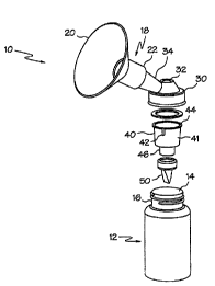
Figure 1 is a perspective illustration of the preferred
embodiment of the self cycling breast pump constructed in
accordance with the principles of the present invention.
Figure 2 is a perspective illustration of the electric
pump means and electric vent valve means of the present
invention.
Figure 3 is a side elevational view of the upper housing
and motor of the electric pump means of the present invention.
8
SL1ESTITUTE SHEET (Rule a6)
CA 02336738 2001-O1-05
WO 00/01431 PCT/1JJS99l1S224
Figure 4 is an exploded view of the present invention
depicting the upper housing, lower housing, elastomeric sheet,
and various other components thereof.
Figure 5 is a schematic diagram of the vent valve control
means and the low battery indicator means of the present
invention.'
Figure 6 is a schematic diagram of the electronic vacuum
control means.
Similar reference characters refer to similar parts
throughout~the several views of the dravrings.
DESCRIPTION OF THE PREFERRED EMBODIMENT
With reference now to the drawings, and in particular to
Figure 1 thereof, a new and improved self cycling breast pump
embodying the principles and concepts of the present invention
and generally designated by the reference numeral 10 will be
described.
The present invention, the new and. improved self cycling
breast pump, is comprised of a plurality of components. .Such
components in their broadest context include a purser bottle,
suction assembly, cap assembly, reservoir, one-way valve,
electric pump means, electronic vacuum control means, electric
valve vent means, electronic valve vent control means, and low
battery indicator means. Such components are individually
configured and correlated with respect to each other so as to
attain the desired objective.
More specifically, it will be noted that the system 10 Of
the present invention includes a purser :bottle 12 with a
circular opening 14 formed on a top face thereof. As shown in
Figure 1. the purser bottle 12 has a peripheral lip 1&
9
SUBSTITUTE SHEET (Rule 2.6)
CA 02336738 2001-O1-05
WO 00/01431 PCTlUS99/15224
integrally formed about the top opening with a plurality of
coaxial threads formed thereon.
Further provided is a suction assembly 18 having an
outboard extent 20 with a frusto-conical configuration. The
outboard extent 20 has a large opening and a small opening.
The suction assembly 18 further includes an inboard extent 22
having a cylindrical configuration integrally formed in
coaxial relation with the small opening of the outboard extent
20.
With reference still to Figure 1, <~ cap assembly 30 is
included with a top face and a periphery integrally formed
thereto and extending dawnwardly therefrom. The periphery has
at least one groove formed in an inner :surface thereof. The
top face of the cap assembly 30 has an aperture 32 formed in a
central extent thereof. For allowing connection of the suction
assembly 18 thereto, the cap assembly 30 further includes a
mounting tube 34 integrally coupled at first end thereof to
the top face of the cap assembly 30 and in communication with
an interior thereof. By this structure, the inboard extent of
the suction assembly 18 may be frictionc~lly engaged with the
mounting tube 34 at predetermined angle of approximately 45
degrees.
A reservoir 40 is included with an upper extent 41 formed
of a bottom face with an aperture formed therein. A
cylindrical periphery is integrally formed with the bottom
face and extended upwardly therefrom to define a top opening.
For reasons that will become apparent later, a plurality of
grooves 42 are formed in an exterior surface of the periphery
adjacent the top opening of the reservoir 40. An annular
flange 44 is formed along the periphery of the reservoir 40
contiguous with the top opening thereof for resting about the
peripheral lip 16 of the purser bottle 12 such that the cap
assembly may be threadedly secured to th.e purser bottle :L2
with an unnumbered gasket situated therebetweeri. Note that the
1a
SUBSTITUTE SHEET (Rule ::6)
CA 02336738 2001-O1-05
WO 00101431 PCT/US99/15224
grooves 42also extend along a lower surface of the flange 44.
When the cap assembly 30 is secured on the nurser bottle, it
is imperative that the grooves 42 providle a passage between
the interior space of the purser bottle and the atmosphere.
The reservoir 40 further includes a lowe::r extent 46 formed of
a vertically oriented tube integrally coupled to the bottom
face of the upper extent about the aperture thereof.
Coupled to the lower extent of the reservoir 40 is a one-
way valve 50 for allowing liquid received from the suction
assembly 18 to pass therethrough to the purser bottle 12.
By this structure, a suction may bE; applied at the
aperture of the cap assembly 30 such that the interior space
thereof and the area within the reservoir 40 may be evacuated.
Evacuation of the purser bottle is prevented by the one-way
valve 50. The evacuation of the cap assembly 30 and reservoir
40 effects removal of milk from a breast: inserted within the
suction assembly 18. when the milk flow~> to the reservoir 40,
it flows through the one-way valve 50 by means of gravity.
Equalization of air within the purser bottle as it is filled
with milk is accomplished via the groove's 42.
As generally shown in Figure 2, electric pump means 60 is
included for affording the above mentioned vacuum. The
electric pump means generates the vacuurn at an inlet 62
thereof upon the activation thereof. It should be noted that
an unillustrated suction tube is conneci:ed between the inlet
62 of the electric pump means and the aperture formed on the
cap assembly 30.
Further provided is electric vent valve means 64 adapted
to vent the vacuum created by the eiect:ric pump means upon the
activation thereof for releasing the vacuum.
11
SUBSTITUTE SHEET (Rule 26)
CA 02336738 2001-O1-05
WO 00l0143I PCT/US99/15224
As can be seen in Figures 3 & 4, the electric pump means
and vent valve means comprise an upper housing 70 with a
planar top face and a planar bottom face. The upper housing 70
has a circular inset portion 72 with a plurality of apertures
74 situated in a first half thereof. Such apertures extend
between a bottom of the circular inset portion and the bottom
face of the upper housing 70. Associated therewith is a
semicircular cut out 76 formed in a se<:ond half of the
circular inset portion 72. The semicircular cut out 76 also
extends between the top face and the bottom face of the upper
housing 70. Further provided is an atmospheric vent 7$ formed
of a square aperture extending between the top face and the
bottom face of the upper housing 70. A pair of vent apertures
80 are formed through the upper housing 70 and are connected
via a vent crossover tube 82 situated on the top face of the
upper housing 70. As best shown in Figure, 3, a vent valve
passage is defined by a groove 84 formed in the bottom face of
the upper housing 70 which is in communication with one of the
vent apertures.80 and extends to a point adjacent the
atmospheric vent 78.
The electric pump means and the vent valve means further
includes a lower housing 90 positioned beneath the upper
housing 70. The lower housing 90 has a bottom face and a
planar top face. A first compartment 92 is situated on the
bottom face in communication with the inlet 62 of the pump
means. A second compartment 94 is situated on the bottom face
in communication with an exhaust port 96. Formed in the top
face of the lower housing and in communication with the second
compartment 94 is a semicircular cut out 100, such
semicircular cut out 100 is situated directly beneath the
plurality of apertures 74 which are pos:i.tioned in the circular
inset portion 72 of the upper housing 70. Associated therewith
is a plurality of apertures 102 formed :in the top face of the
lower housing 90 and in communication w:Lth the first
12
SUBSTITUTE SHEET (Rule 2b)
CA 02336738 2001-O1-05
WO 00/01431 PCT/US99/15224
compartment 92. The plurality of apertures 102 of the lower
housing 90 are situated directly beneath the semicircular
cutout 76 situated in the circular inset portion 72 of 'the
upper housing 70. A vent aperture 104 is formed in the 'top
face of the lower housing 90. Such vent aperture 104 is
designed to remain in communication with the first compartment
92 of the lower housing 90 and the vent aperture, of the upper
housing 70 which is not in communication with the groove. A
circular cut out 106 is formed in the lower housing 90 and is
further extended between the top face and the bottom facie
thereof.
Still yet another component of the electric pump means
and the vent valve means is a planar elastomeric sheet 110.
Such sheet is situated between the upper housing 70 and the
lower housing 90. Formed in the sheet of elastomeric material
is a plurality of flaps 112 situated over the apertures 102 of
the lower housing 90 and the apertures '74 located in the
circular inset portion 72 0~ the upper housing 70. It should
be noted that the eiastomeric sheet 110 further resides
between the circular cut out 106 of the lower housing 90 and
the pair of apertures and atmospheric of=nt 78 of the upper
housing 70. The elastomeric sheet 110 has an aperture lI2
formed therein for allowing continuous communication between
the vent aperture 104 of the lower hous_Lng 90 and the
associated vent aperture of the upper housing 70.
As shown in Figure 4, the electric pump means further
includes a diaphragm 120 sealed about the circular inset
portion 72 of the upper housing 70 by means of a retainer 119.
The diaphragm 120 has a tab 122 centrally coupled to a top
face thereof with a bore formed therein. The electric pump
means further has a motor 124 with an eccentrically configured
post coupled to a rotor thereof. As such, the post may be
rotatably situated within the bore of the tab 122 and upon the
1. 3
SUBSTITUTE SHEET (Role :Z6)
CA 02336738 2001-O1-05
WO 00/01431 PCT/US99/15224
actuation of the motor 124, the tab 122 and the diaphragm 120
are moved up and down. This effects the suction of air through
the apertures 102 of the lower housing 90 and expelling of air
through the apertures 74 of the upper housing 70 thus creating
a vacuum at the inlet 62 of the electric pump means while
expelling air out the exhaust port 96. The flaps of the
elastomeric sheet ensure one-way passage of air through the
respective apertures. Passage of air is afforded by allowing
the flaps to move within the associated semicircular cut out
away from their respective apertures. The exhaust port =~s
ideally situated exterior a housing in which the above
components reside. As such, when the system is flushed with
water, it may be expelled without contacting any of the vital
components positioned in the housing.
With reference still to Figure 4, 'the vent valve means
also includes a plunger 130 with a cylindrical configuration
slidably situated within the atmospheric vent 78 for biasing
the elastomeric sheet 110 within the circular cut out 106 of
the lower housing 90 upon the actuation thereof. This allows
communication between the atmospheric vE~nt 78 and the groove
84. Upon such communication, a vacuum ressiding in the first
compartment 92 is released through the atmospheric vent 78 via
the vent crossover tube 82 and groove 84.
For affording intermittent suction at the inlet 62 of the
electric pump means, electronic vent control means 140 is
provided. The electronic vent control means 140 is adapted for
determining a rate of activation of the electric vent valve
means thereby creating an automatic cyc7_ing suction at the
inlet 62 of the electric pump means. As shown in Figure 5, the
electronic vent control means 140 prefex-ably comprises a 555
timer IC1 designed for a stable operation. The 555 is adapted
to produce a square wave at an output thereof upon the receipt
of power. Such square wave has a duty cycle which is
I4
SUBSTITUTE SHEET (Rule 26)
CA 02336738 2001-O1-05
WO 00/01431 PCTNS99/15224
determined by the selection of resistor R1,' resistor R2, and
capacitor C1, as is commonly known in the art. As will become
apparent hereinafter, the duty cycle is preferably tailored to
effect a suction/release cycle which resembles that of a
child. Such suction/release cycle consists of an approximate 1
second suction and a 1 second release. As shown in Figure 5,
the output of the 555 timer is connected to a diode D1 which
is in turn connected to a base of a transistor Q1. The
transistor Ql is connected at its collector to a solenoid in
which the plunger of the electronic vent control means is
situated to define a transducer. The transistor Q1 operates as
an amplified switch in that upon the receipt of a high pulse,
the solenoid is actuated with a sufficient current thereby
forcing the plunger against the elastomeric sheet 1I0. This,
in turn, vents the vacuum of the first compartment 92. It
should be noted that a diode D2 is coupled between the
collector and the emitter of the transistor to preclude a
reverse polarity voltage across transistor Q1 during
deactivation. As an option, the transistor may be removed in
favor of a substitute for the 555 timer IC1 which is cap;~ble
of producing sufficient current for the proper operation of
the traducer and solenoid combination. Still yet another
option is to utilize a coil L1 with a higher DC resistance in
lieu of the transistor Q1. Both alternatives are feasible and
should be designed with the amount of necessary force afforded
by the plunger in mind.
To manually release the vacuum at the inlet 62 of the
electric pump means, a manual vent control means may be
utilized. Preferably, such manual vent control means includes
a switch S1 connected between a source of power and the base
of the transistor Ql. By this structure, an artificial high
pulse is generated upon the depression of such switch. T:he
function of diode Di now becomes apparent in that it functions
SUBSTITUTE SHEET (Rule 26)
CA 02336738 2001-O1-05
WO 00/01431 PCT1US99/15224
to prevent a short circuit through pin 3 of 555 timer IC1 when
pin 3 of the 555 timer ICl is low.
With reference now to Figure 6, it: is shown that an
electronic vacuum control means 150 is provided. Such
electronic_vacuum control means 150 is adapted for allowing
the manual governing of the level of vacuum generated by the
electric pump means. To accomplish such., the speed of the
motor 124 of the electric pump means is governed. The speed of
the motor 124 is controlled by means of a variable duty
oscillator IC2. The component type of IC2 is the same as IC1.
A~plurality of resistors R4 & R5, diodes D5 & D~, and a
capacitor C3 are configured to dictate the specific operation
of IC2. Also included is a potentiometer VR1 which has an
associated dial 152 available for manipulation by a user. The
potentiometer VRl allows a user to govern the duty cycle of
the pulse which is transmitted from the output of the variable
duty oscillator IC2. The output of the variable duty
oscillator IC2 is in turn connected to the base of a
transistor Q2. Such transistor Q2 is connected at a col7_ector
thereof to the motor 124. In use, the ~,nePr~ of thA mnt"r
and the suction thereby afforded is increased and decreased
upon the variation of the duty cycle via the dial. Tt should
be noted that the average voltage or DC voltage at the output
of the IC2 is proportional to the duty cycle and further the
voltage delivered to the motor 124 is the amplitude of the
output pulse of the oscillator IC2 minus the voltage drop
across the transistor Q2. A diode D4 is connected between the
collector and emitter of the transistor for reasons similar to
that of transistor Q1. The frequency of the pulse at the
output of IC2 has no effect on the speed of the motor 124 and
therefore is deemed not critical except that lower
frequencies(30Hz) result in higher avai7_able motor torque
especially at lower motor speeds. It should be noted that the
potentiometer is of the type equipped with a switch S2 that is
16
SUBSTITUTE SKEET (Rule 26)
CA 02336738 2001-O1-05
WO 00/01431 PCTIUS99/15224
open when the dial 152 is turned entirely in a clockwise
direction. A detent is formed on the shaft of the
potentiometer VR1 to indicate whether the dial is turned
entirely in the clockwise direction. Such switch S2 allows a
user to selectively supply power to the electronic components
of the present invention.
For monitoring a portable power supply such as a battery,
a low battery indication means 160 is provided for alerting a
user upon an available power of the battery falling below a
predetermined level. While the present :invention i° ideally
equipped to accommodate power supplied by a battery, it should
be noted that the present invention may also be powered by a
conventional power receptacle. While noi~ illustrated, the
present invention includes an AC adapter with an associated
switch which disconnects the batteries from the associated
circuitry upon the employment of the AC adapter. As shown in
Figure 5, the low battery indication means includes a chip IC3
which is identical to IC1 & IC2 utilized in the previous
circuits. In use; when the batteries di:>charge to a voltage of
approximately 4 Volts, a light emitting diode D7 actuates such
that it is visible to a user. The ratio of a pair of
associated resistors R7 & R8 along with the zener diode D8
determine the threshold voltage at which the light emitting
diode is actuated. The present invention is equipped with
numerous features for affording high efficiency. The apertures
74 & 202 of the upper and lower housing 90 are .095 in
diameter and the inlet 62 and exhaust part 96 of the electric
pump means are no less than .20 inches, inside diameter. This
is to minimize pressure loss as air passes therethrough.
Further, by the utilization of the reservoir 40, the amount of
the volume required to be evacuated is reduced thus lessening
the amount of power required.
17
SUBSTITUTE SHEET (Rule i:6)
CA 02336738 2001-O1-05
WO 00/01431 PCT/US99/15224
_ As to the manner of usage and operation of the present
invention, the same should be apparent from the above
description. Accordingly, no further discussion relating to
the manner of usage and operation will :be provided.
With respect to the above description then, it is to be
realized that the optimum dimensional relationships for the
parts of the invention, to include variations in size,
materials, shape, form, function and manner of operation,
assembly and use, are deemed readily apparent and obvious to
one skilled in the art; and all equivalf=nt relationships to
those illustrated in the drawings and d<=scribed in-the
specification are intended to be encomp<~ssed by the present
invention.
Therefore, the foregoing is considered as illustrative
only of the principles of the invention" Further, since
numerous modifications and changes will readily occur to those
skilled in the art, it is not desired to limit the invention
to the exact construction and operation shown and described,
and accordingly, all suitable modifications and equivalents
may be resorted to, falling within the scope of the invention.
18
SUBSTITUTE SHEET (Rule :Z6)