Note: Descriptions are shown in the official language in which they were submitted.
CA 02336907 2001-01-09
WO 99/21496 PCT/US98/21033
DEVICE FOR PLASMA INCISION OF MATTER WITH A SPECIFICALLY
TUNED RADIOFREQUENCY ELECTROMAGNE'TIC FIELD GENERATOR
Background - Field of Invention
This invention relates to a plasma generation device employed to place an
incision
into matter with a harmonious plasma cloud, specifically to harmonious plasma
clouds
initiated and sustained by electromagnetic energy waves transmitted from a
radiofrequency signal generator system. This system is impedance matched,
frequency
matched and output power matched to the incising harnlonious plasma cloud
which is
initiated, sustained and controlled by our device and in the process coats the
activated
transmitter incision probe of our invention.
Background - Description of Prior Art
Hardened physical blades, such as a metal blade, a sapphire blade, or a
diamond
blade are the devices most frequently employed to place an incision into
matter. Such
incisions are based on frictional physical interactions between a sharp, acute
edge of
hardened matter against a surface of the matter to be incised. Such purely
physical
methods of one hardened matter attempting to cut through another hardened
matter are
inefficient and therefore experience significant inefficiencies such as
frictional resistance
when the matter being incised is solid and dense such as biologic tissue, wood
products or
even metal. For these reasons, others have resorted to devices such as
electronically
generated incisions, electro-incisions or electrosurgery of matter. When these
types of
CA 02336907 2001-01-09
WO 99/21496 PCT/US98/21033
2
devices are used to place an incision into matter, uncontrolled plasma arcs
induce
substantial burns or volatilization of matter while electrical ohmic
resistance in the matter
to be incised creates a heating effect due to phenomenon such as dielectric
hysteresis and
eddy currents. These last two phenomenon produce an effect known as diathermy
which
may result in a physical reaction that can produce an incision in matter. This
approach has
received limited use since its shortcomings include extensive damage to matter
outside of
the intended incision path with the resultant production of burning and
charring which
frequently causes unpleasant smelling fumes. The inefficiency of classic
electro-incision
units is manifested by the high power needed to produce a, cutting effect at
the incising tip,
usually in excess of 50 watts of power. This relatively high power output
needed in
classic electro-cutting or electrosurgical units is secondary to the cutting
inefficiency of
these units which operate on a combination of classic ohmic diathermy as well
as unstable,
uncontrolled, caustic plasma arcing which is a form of dislharmonious plasma.
Lasers have also been used to incise and cut; however, these units are
expensive
and require a large amount of system input energy to create a laser beam with
sufficient
power to cut or make an incision into matter. Lasers have been used to
generate plasma
and are used in processes such as etching in the field of microelectronics.
Plasma arcing can be found in a number of areas :such as welding arcs, spark
plug
arcs, lightening bolt arcs, neon lights, fluorescent lights, and
electrosurgical arcs.
Uncontrolled arcing, per se, is a form of disharmonious plasma flow and
represents
uncontrolled flow turbulence of ionized atomic particles in plasma with a
substantial level
of atomic particle chaos in the plasma. The atomic particle turbulence in
plasma arcs
represents a form of atomic particle chaos and the uncontrolled nature of the
atomic
particle chaos causes a substantial quantity of energy spillover into matter
outside of the
intended path of incision and thereby may produce excessive heating. This
level of
substantial heating is produced when unwanted arcing occurs with classic
electrocutting or
electrosurgical units. This energy spillover into matter surrounding the
intended path of
incision into matter results in energy exposure and danaage to the surrounding
matter.
Merely reducing the cutting tip power does not by itself significantly reduce
the level of
the plasma atomic particle chaos in as much as it does not greatly decrease
the flow
turbulence of the ionized atomic particles that comprise a plasma arc.
Moreover, our
invention uses an array of physical chemistry principles to minimize the
atomic particle
CA 02336907 2001-01-09
WO 99/21496 PCT/US98/21033
3
chaos of classic disharmonious' plasma arcing as well as control the physical
characteristics of the plasma produced by our device. Our invention minimizes
disharmonious plasma arcing by reducing the atomic particle turbulence in the
plasma
cloud thereby greatly reducing the plasma cloud ator.nic particle chaos and
thereby
creating a harmonious plasma cloud. Harmonious plasma cuts in a more
controlled,
efficient and safer manner because the atomic particle components in a
harmonious
plasma cloud exist in a more stable, balanced, and controlled state with a
higher order of
organization and less atomic particle turbulence than disharmonious plasma.
Our
harmonious plasma cloud is furthermore compressed, conitrolled, contoured and
shaped by
utilizing the Pinch Effect of physics. Our compressed plasma cloud is then
trapped and
contained by the Magnetic Bottle Phenomenon well knovm to physicists and
employed in
fields such as nuclear physics. As opposed to classic electrocutting or
electrosurgical
units, our device cuts with a harmonious controlled plasma cloud rather than
classic ohmic
diathermy.
Objectives and Advantages
Accordingly, several objects and advantages of the present invention are:
(a) to provide an incisional device that uws an inexpensive electronic
radiofrequency signal generator, amplifier, impedance matching and output
conditioning
network, as well as a transmitter probe to generate, amplify, condition and
transmit an
electromagnetic wave.
(b) to employ a solid, non-hollow conductive radiofrequency transmitter probe
to
create.maintain and control plasma. Nonetheless, the transmitter probe, may be
completely
hollow or partially hollow in design.
(c) to produce a plasma cutting blade from an electronic electromagnetic field
generator system which requires lower system input energy relative to other
electrocutting
incisional methods presently in use, even as low as 2 watts of average input
power.
Likewise, this system requires lower system output energy relative to other
electrocutting
incisional methods presently in use, even as low as 1 watt of average output
power.
(d) to create a cutting plasma cloud without the necessity of injecting an
ionizable
gas into the field of cutting as is seen in plasma generating devices such as
plasma torches
and etching systems in plasma chambers.
--- ~
CA 02336907 2001-01-09
WO 99/21496 PCT/US98/21033
4
(e) to create a harmonious plasma cloud with substantially reduced atomic
particle
chaos and turbulence than other plasma cutting devices by irnpedance matching
and
conditioning the energy from our electromagnetic generator system to the
plasma cloud
that surrounds and coats the activated transmitter incising electrode tip.
(f) to create a harmonious plasma cloud with substantially reduced atomic
particle
chaos and turbulence than other plasma cutting devices by frequency matching
the energy
from our electromagnetic generator system to the atomic particle oscillation
harmonics
and precession frequencies of the plasma cloud which coats and surrounds the
activated
transmitter incising electrode tip.
(g) to create a harmonious plasma cloud with subsaantially reduced atomic
particle
chaos and turbulence than other plasma cutting devices by power matching our
electromagnetic generator system output power to the power requirements needed
to
initiate and sustain a harmonious plasma cloud.
(h) to produce a tightly coupled, high efficiency transfer of the
electromagnetic
waveform generator energy into the plasma cloud surrounding and coating the
activated
transmitter incising electrode tip thereby reducing the radiofrequency
generator/amplifier
output power needed to initiate and sustain a harmonious plasma cloud
surrounding the
activated transmitter incising electrode tip.
(i) to utilize the physics principle known as the Pinch Effect in order to
concentrate, compress and contour the harmonious plasma cloud coating the
activated
transmitter incising electrode tip.
(j) to employ the physics principle known as the Magnetic Bottle Effect to
trap and
contain the harmonious plasma cloud and thereby elimiiiate the need. of a
solid, matter
confinement container to encase the plasma cloud. We tllereby eliminate the
need for a
hollow plasma retention chamber near the activated transrniitter incising
electrode tip.
(k) to utilize the physical chemistry principle of Tunnelling to reflect the
electromagnetic wave transmitted by the activated transniitter incising
electrode tip off of
matter surrounding the harmonious plasma cloud and the:reby reflect the
electromagnetic
wave back into the harmonious plasma cloud surrouriding the activated
transmitter
incising electrode tip. In this manner, we are employing the Tunnelling Effect
to create an
electromagnetic shield which minimizes transmitted electromagnetic radiation
from
interacting and penetrating into matter outside of the intended path of
incision. This
CA 02336907 2001-01-09
WO 99/21496 PCTIUS98/21033
system acts to minimize the potential side effects of electromagnetic
radiation exposure.
Furthermore, this electromagnetic radiation reflected back into the plasma
cloud acts to
further energize the harmonious plasma cloud thereby further reducing the
output energy
required from the electromagnetic generator system to sustain the plasma cloud
for
effective cutting.
(1) to use a harmonious plasma cloud condensed around the activated
transmitter
incising electrode tip to focus the kinetic energy of the cutting plasma into
a thinner
cutting path in order to produce a discrete, clean incision into matter with
minimal impact
or side effects to matter outside of the intended path of incision.
(m) to produce an alternative to purely physical energy cutting techniques
such as
knives and metal blades, while also.providing a more efficient, more
effective, more
precise, and cleaner cutting device than other cutting modalities presently
available.
(n) to produce a less expensive cutting device than other high technology
cutting
devices commercially available, such as laser.
Drawing Figures
Two drawings are enclosed in this patent application.
Fig 1 shows a plasma cutting device with a capacitive coupling between the
incising transmitter probe system and the matter into which an incision is
placed.
Fig 2 shows a plasma cutting device with a resistive coupling between the
incising
transmitter probe system and the matter into which an incision is placed.
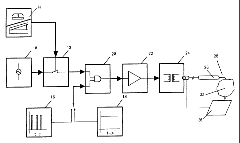
ReferenceNumerals in Drawings
radiofrequency signal generator
12 radiofrequency switch
14 on-off button / on-off switch
16 burst mode duty cycle generator
18 continuous mode free running generator
signal gate
22 power amplifier
24 impedance matching and output conditioning network
26 incising transmitter handpiece
CA 02336907 2001-01-09
WO 99/21496 PCT/US98/21033
6
28 incising electrode tip
30 capacitive coupling plate
32 matter into which an incision is placed
34 resistive coupling electrode
Summary of the Invention
Our device is a specifically tuned radiofrequency generator and power
amplifier
system. Our invention does not require substantially complicated d'esigns for
the
transmitter incising electrode tips nor elaborate plasma control devices such
as a tokamak
or cyclotron. The electromagnetic wave created by our system is a form of
radiant
electromagnetic energy and is transmitted from the active transmitter incising
electrode tip
of our system. This radiant electromagnetic energy is specifically conditioned
to interact
with atoms and molecules at the interface of the active txansmitter incising
electrode tip
and the matter into which an incision is placed. The reaction of radiant
electromagnetic
energy with atoms and molecules at the incising electrode tip surface includes
a
photoelectric effect and thermal ionization which strip electrons from the
atornic orbitals
of atoms at the interface of the active incising electrode tip and the matter
into which an
incision is placed. The radiant energy acts to excite electrons and ions along
the surface of
the active transmitter incising electrode tip. The result of such processes is
atomic
transformation to higher energy ions and electrons. The free charged atomic
particles
move rapidly through space before colliding with electrons of other atoms in
the electrode
interface thereby knocking additional electrons out of the:ir atomic orbitals.
Repeating this
process produces a chain reaction of charged atomic particle collision known
as an
Avalanche Effect which helps trigger the formation of a cloud of plasma along
the active
transmitter incising electrode tip surface. Our device is impedance matched,
frequency
matched, power matched and tuned to the plasma cloud coating the active
transmitter
incising electrode tip. Our device conditions the generated electromagnetic
waveform to
allow a tightly coupled, highly efficient energy transfer to the plasma cloud
in order to
provide maximum energy transfer into the plasma cloud with minimal loss of
radiant
electromagnetic energy into the matter surrounding the intended path of
incision. Physical
chemistry principles are employed to control the shape and characteristics of
the plasma
cloud, including the reduction of atomic particle chaos in the plasma cloud.
In this way,
CA 02336907 2001-01-09
WO 99/21496 PCT/US98/21033
7
our device produces a harmonious, controlled plasma that focuses energy into
the intended
path of incision as opposed to the caustic, disharmonious plasma arcing seen
in classic
electrocutting or electrosurgical units. This cloud of harmonious plasma
manifests lower
atomic particle chaos and produces a more efficient incision in matter than
classic
electrocutting or electrosurgical systems.
Description - Figs. 1 to 2
A typical embodiment of the plasma incision device of the present invention is
illustrated in Fig 1 and Fig 2. An output signal of a radiofeequency signal
generator (10) is
switched on and off with a radiofrequency switch (12) by several means such as
an on:off
button or on-off switch (14). The output signal of the radiofrequency signal
generator is
then slaved through a signal gate (20) to either a burst mode duty cycle
generator (16) or a
continuous mode free running generator (18). The burst mode or continuous mode
radiofrequency output signal is then amplified through a power amplifier (22).
The output
signal of the power amplifier is then conditioned with an impedance matching
and output
conditioning network (24) and is then channeled into an active incising
transmitter
handpiece (26). When activated, an incising electrode tip (28) at the extreme
end of
incising transmitter handpiece (26) is coated with a plasma cloud which is
used to place an
incision path into the matter into which an incision is placed (32). Matter
into which an
incision is placed (32) nia.y be coupled to our plasma cutting system either
by a capacitive
coupling plate (30) or a resistive coupling electrode (34). Active incising
electrode tip
(28) is preferably a solid, non-hollow conductor althougih a partial or
completely hollow
incising electrode tip may be utilized. Incising electrode tip (28) is
preferably linear or
curvilinear in design; however, the shape of incising electrode tip (28) is
not necessarily
specific in design and may even have a loop or polygon design.
Operation - Figs i to 2
Our invention for incising matter is different from a11 prior devices for
incising
matter. An on-off button / on-off switch (14) is used to activate or
deactivate a
radiofrequency switch (12). This therefore regulates the transmission of an
output signal of
a radiofrequency signal generator (10). Output signal of a. radiofrequency
signal generator
(10) is further controlled such that its transmission is activated or
deactivated by a burst
CA 02336907 2001-01-09
WO 99/21496 PCT/US98/21033
8
mode duty cycle generator (16) or by a continuous mode free running generator
(18).
Output signal is amplified by a power amplifier (22) and then conditioned by
an
impedance matching and output conditioning network (24). Output signal is then
channeled through an incising transmitter handpiece (26).. Matter into which
an incision is
placed (32) may be linked to our invention by a capacitive coupling plate (30)
or a
resistive coupling electrode (34). Output signal is transmitted from a plasma
cutting
device by an incising electrode tip (28), creating a cloud of plasma to coat
incising
electrode tip (28). This plasma coat can react with atorns and molecules of
matter and
thereby place an incision path into matter into which an incision is placed
(32).
Our systera has similarities to standard radio transmission systems which are
impedance matched to atmospheric air, whereas our system is impedance matched,
frequency matched, power matched as well as tuned to a harmonious plasma cloud
surrounding the active incising electrode tip (28). Although our invention
bears
similarrties to other electromagnetic wave transmission systems, it employs
and integrates
a substantial number of principles of physics and chemistry in a manner which
allows us
to create a novel device to place a clean and efficient incision into matter.
The production of harmonious plasma around the active incising electrode tip
(28)
of our device results in a visible, organized plasma cloud which may be
initiated, sustained
and modified by our plasma cutting system. This harmonious plasma coating the
activated
incising electrode tip (28) also manifests substantially reduced atomic
particle chaos and
turbulence. in the plasma cloud compared to other plasrna cutting systems,
thereby our
device produces distinct visible and electronic characteristics.
The harmonious nature of this plasma cloud allows an increased concentration
of
energy in the intended path of incision with less energy spillover outside of
the intended
path of incision. Thereby, this device is able to achieve a cleaner, more
precise, more
powerful and more efficient incision with less impact on matter outside of the
intended
path of incision than classic electrocutting systems.
Plasma is the least abundant of the four types of matter to be found on earth,
although it is the most abundant form of matter in the universe. Examples of
plasma on
earth include: welding arcs, spark plug arcs, neon light arcing, arcs around
lightning
discharges as well as uncontrolled, caustic plasma arcs seen in electrocutting
or
electrosurgery. Plasma is also used in fields such as serr.iiconductor etching
but is herein
CA 02336907 2001-01-09
WO 99/21496 PCT/US98/21033
9
produced by expensive and high energy consumption systems such as lasers or
elaborate
plasma etching chambers. The levels of atomic particle turbulence and chaos
manifested
by classic electrocutting or electrosurgical units are employed by us as a
relative standard
for defining an increase or decrease in atomic particle turbulence or chaos in
plasma.
Our system employs an inexpensive, electronic radiofrequency
generator/amplifier
system to produce, condition and transmit a continuous or pulsed
electromagnetic field
from an incising electrode tip (28). The cycle time of the electromagnetic
field pulsed
mode is variable and each complete on-off cycle of the' pulsed mode may be as
short as
0.000001 of a second. Specific parameters of this electromagnetic field
generator system
are largely determined by the atomic particle composition along the interface
of the
incising electrode tip (28) and the matter into which an incision is placed
(32). Our system
utilizes the atoms along the interface of the incising electrode tip (28) and
the matter into
which an incision is placed (32) to generate a plasma cloud as opposed to
systems which
require an ionizable gas to be injected into the field of incision and
thereupon have the
injected gas energized and converted into plasma. Nonetheless, our plasma
cutting system
may employ supplementary ionizable gas fed into the field of the incising
electrode tip
(28) in order to augment the cutting process. Our inver.ition does not,
however, require
substantially complicated designs for the transmitter incising electrode tips
nor elaborate
plasma control devices such as a tokamak or cyclotron.
The electromagnetic wave created by our system is a form of radiant
electromagnetic energy and is transmitted from the active incising electrode
tip (28) of our
system. The radiant electromagnetic energy is specifically conditioned to
interact with
atoms and molecules at the - surface of the active incising electrode tip
(28).
Electromagnetic frequencies secondarily produced from atomic particle
interaction and
dynamics at the plasma incising electrode tip (28) play a substantial role in
the system
function and effectiveness. Harmonic frequencies of the fundamental generated
electromagnetic waveform often play a substantial role ini system function,
dynamics and
effectiveness. The radiant electromagnetic energy interaction with atoms and
molecules
includes thermal ionization and the photoelectric effect which strip electrons
from the
atomic orbitals of atoms at the interface of the matter into which an incision
is placed (32)
and the incising electrode tip (28). Such processes result in atomic
transformation of atoms
and molecules into ions and free electrons. The free charged atomic particles
move
CA 02336907 2001-01-09
WO 99/21496 PCT/US98/21033
through space before colliding with electrons of other ellectrode interface
atoms thereby
knocking more electrons out of their atomic orbitals. Repeating this process
produces a
chain reaction of charged atomic particle collision known as an Avalanche
Effect which
thereby participates in the forma.tion of a cloud of plasma at the surface of
the active
incising electrode tip (28).
Our device is impedance matched, frequency matched, power matched and tuned
to the plasma cloud coating the incising electrode tip (28). Our device
conditions the
transmitted electromagnetic waveform to provide a tightly coupled, highly
efficient energy
transfer to the plasma cloud in order to allow maximum energy transfer from
the incising
electrode tip (28) into the plasma cloud with minimal loss of electromagnetic
radiant
energy into the matter surrounding the intended path of incision. Physical
chemistry
principles are employed to control the shape and characteristics of the plasma
cloud
including the regulation of atomic particle chaos in the plasma cloud. In this
way, our
device produces a harmonious, controlled plasma that facuses energy into the
intended
path of incision as opposed to the caustic, disharmonious plasma arcing seen
in classic
electrocutting or electrosurgical units. This cloud of harinonious plasma
possesses lower
atomic particle chaos and turbulence than classic electrocutting or
electrosurgical systems,
thereby producing a more efficient incision into matter than found in classic
electrocutting
or electrosurgical systems which are seen to generate disharmonious plasma
arcs.
The use of electromagnetic fields to regulate the order of atomic particles
proliferates the literature of electronics, physics, and chemistry. Examples
of the use of
electromagnetic fields to create increased atomic particle order occurs
frequently with
modern technology and even includes turbine electric generators which produce
electricity
for our communities. Likewise, Nuclear Magnetic Resonance (NMR) devices use
magnetic fields to transform randomly oriented atomic particles (a higher
level of atomic
particle chaos or disorganization) into atomic particles oriented in the plane
of the
magnetic field (a lower level of atomic particle chaos or disorganization). As
an analogous
process, our device employs an electromagnetic wave: which is impedance
matched,
frequency matched, power matched and tuned to initiate, sustain and condition
a plasma
cloud around the incising electrode tip (28) as well as reduce the atomic
particle
disorganization and chaos in the plasma cloud. In this way, the atomic
particles in the
plasma cloud coating the incising electrode tip (28) of our invention are
conditioned such
CA 02336907 2001-01-09
WO 99/21496 PCTIUS98/21033
11
that they possess less atomic particle chaos and a higher order of
organization than seen in
plasma arcs of classic electrocutting systems thereby al:[owing our device to
generate a
harmonious plasma cloud.
The levels of atomic particle turbulence anci chaos manifested in classic
electrocutting or electrosurgical units are employed by us to create a
relative standard or
baseline from which we may define and demonstrate an increase or decrease in
the
magnitude of atomic particle turbulence or chaos in plasma.
The effects of electromagnetic wave frequency anci electromagnetic wave power
or
field strength are interrelated and dynamic. Nuclear Magnetic Resonance
teaches us that
precessing atomic particles may absorb radiant electromagnetic energy when
that atomic
particle precession frequency and the frequency of the radiant electromagnetic
energy are
in resonance. In other words, Nuclear Magnetic Resonance demonstrates that
efficient
absorption of electromagnetic energy occurs when the atomic particle is
frequency
matched to the radiant electromagnetic wave frequency. Our device demonstrates
an
analogous relationship regarding the importance of frequency matching our
transmitter
electromagnetic wave to the atomic particle properties composing the plasma
cloud
surrounding the incising electrode tip (28).
Nuclear Magnetic Resonance also teaches us that the frequency of atomic
particle
precession may be directly related to the strength of the magnetic field in
which the atomic
particle exists. Therefore, the stronger the applied r.nagnetic field, the
higher the
electromagnetic field frequency required to achieve the resonance needed for
efficient
energy absorption. Likewise, the electron gyrofrequencies in the "D" and "E"
layers of the
earth's ionosphere substantially increase as we move from the equator toward
the
magnetic poles of the earth, either north pole or south pole. Respecting
similar scientific
principles, our device addresses the issue of field strength and
electromagnetic frequency
and thereby power matches and frequency matches our transmitted
electromagnetic wave
to the atomic particles composing the plasma cloud coating the incising
electrode tip (28).
Nonetheless, individual parameters of our electromagnetic field generator
system vary
substantially when placing an incision into different types of matter and are
substantially
dependent upon the atomic particle composition along the interface of the
incising
electrode tip (28) and the matter into which an incision is placed (32).
CA 02336907 2001-01-09
WO 99/21496 PCT/US98/21033
12
Strong interrelationships exist between a transmitted electromagnetic wave and
the
molecular composition surrounding the transmitter element. Ham radio operators
utilize a
measurement termed a Standing Wave Ratio to characterize the percentage of
electromagnetic wave power transmitted into the atmosphere. The Ham radio unit
may
then have its transmitted electromagnetic waveform condlitioned in order to
maximize the
percentage of electromagnetic energy transmitted into the atmosphere. Our
device is
analogous in that it maximizes transmitted electromagnetic radiation with an
impedance
matching and output conditioning network which provides a tightly coupled,
highly
efficient transfer of electromagnetic waveform energy into the plasma cloud
which coats
and surrounds the active incising electrode tip (28). In this manner, our
device achieves an
efficient transfer of radiant electromagnetic energy into the plasma cloud
surrounding the
incising electrode tip (28).
Arcing is a form of disharmonious plasma flow and represents uncontrolled,
turbulent flow of ionized atomic particles in plasnia, the:reby producing
increased atomic
particle chaos and turbulence in the plasma. As has been shown in other fields
such as
Nuclear Magnetic Resonance (NMR), merely reducing the cutting tip power does
not in
itself significantly improve the piasma harmony in as much as it does not
greatly decrease
the flow turbulence or flow chaos of the ionized atomic particles that make up
a plasma
arc. As with other forms of matter, plasma has a wide range of physical
presentation
including a wide range of temperature, density, flow characteristics, atomic
particle
components, etc. On earth, plasma arcing can be found in a number of areas
such as
welding arcs, spark plug arcs, lightning bolt arcs, neon lights and
electrocutting or
electrosurgical. . ares. The - substantial intensity of atomic particle
turbulence in classic
electrocutting plasma arcs represents a form of elevated atomic particle
chaos, wherein the
uncontrolled nature of the atomic particle chaos is causecl by turbulent flow
of the atomic
particles in the plasma cloud. This form of plasma represents disharmonious
plasma and
when used for cutting results in substantial heating or a significant quantity
of energy
spillover into matter outside of the intended path of incision. This energy
spillover
extending beyond the intended path of incision into nuttter results in energy
exposure,
thermal exposure and damage to surrounding matter. In this way, our invention
minimizes
classic plasma arcing by substantially reducing the atomic particle turbulence
and chaos in
the plasma cloud, and thereby acts to generate a harmonious plasma cloud.
CA 02336907 2001-01-09
WO 99/21496 PCT/US98/21033
13
As the electromagnetic field traverses the thin coating of harmonious plasma
surrounding the activated incising electrode tip (28), the electromagnetic
field is slowly
damped or decreased in amplitude. Finally, the electromagnetic field will pass
completely
through the plasma cloud and will encounter matter outside of the intended
incision path,
namely the matter which surrounds the cloud of incising plasma. According to
the
physical chemistry principle of Tunnelling, the generated electromagnetic wave
then
encounters a barrier to which it is not tuned nor impedance matched and
thereby a
substantial percentage of the remaiining energy of the electromagnetic wave is
reflected
back into the harmonious plasma cloud. This reflected electromagnetic energy
acts to
further energize the molecular particles in the plasma cloud, thereby reducing
the output
energy which must be transmitted by the electromagnetiic wave generator
system. This
process also serves to minimize the percentage of total electromagnetic
radiation that
penetrates into, that reacts with, and that presents potential radiation
exposure damage to
matter outside of the intended incision path.
The centripetal force of our generated magnetic field is used to control the
distance
between the atomic particles in the harmonious plasma cloud and the surfa.ce
of the
activated incising electrode tip (28). The ionized particles travel in spiral
paths in magnetic
fields while the individual ionized particles may simultaiieously be
oscillating, vibrating,
spinning and/or precessing. Furthermore, the Pinch Effect which has been used
for many
years in fields such as plasma physics is employed in our system. In this way,
we are able
to compress, contour, shape and control the harmonious plasma cloud with a
solid or
hollow transmitter incising electrode tip (28). We also employ the Magnetic
Bottle Effect
used -in fields such as nuclear physics to trap and contaain the compressed
plasma cloud
without the need of solid matter containment vessels and thereby avoid the
requirement to
employ hollow or cavity contai;ning incising tip probes to trap and control
the plasma
cloud. Increasing the density of atomic particles in the harmonious plasma
cloud allows
us to substantially increase the plasma cloud power density, thereby improving
the cutting
efficiency and power of the plasma cloud.
Furthermore, compressing the plasma cloud causes a substantial decrease in the
cross sectional diameter of the plasma cloud thereby decreasing the width of
the intended
incision path as well as minimizing side effects or potential adverse impact
on matter
outside of the intended path of incision. Once the electromagnetic wave
generator system
CA 02336907 2001-01-09
WO 99/21496 PCT/US98/21033
14
has its power turned oM the energy level of the harmonious plasma cloud
rapidly decays
to a point at which the atomic particles comprising the plasma cloud cannot be
sustained in
the state of matter known as plasma.
Conclusion, Ramifications, and Scope
Accordingly, the reader will see that err.iploying a specifically tuned
electromagnetic wave to generate a harmonious plasina which may have its
shape,
contour, power density and physical characteristics controlled allows us to
produce a more
efficient, more controlled, less toxic and more cost effective method of
incising matter.
Whereas classic electrocutting or electrosurgical units employ inefficient
classic
ohmic diathermy to produce incision into matter, our iradiofrequency generator
system
utilizes its conditioned, transmitted power to create and siustain a thin
cloud of harmonious
plasma which coats the incising electrode tip. Thereby, less energy is
required by our
invention than classic ohmic electrocutting or electrosw-gical systems. The
incision into
matter produced by our invention is created by the interaction of the
harmonious plasma
cloud coating our incising electrode tip and the matter into which an incision
is placed. In
effect, an incision into matter is created by the energy of a controlled,
harmonious cloud of
plasma atomic particles surrounding an activated incising electrode tip.
Furthermore, our
plasma incising device has the additional advantages in that
= it permits an inexpensive production of plasma;
= it permits an efficient production of plasma;
= it permits a controllable production of plasma;
= it permits the production of a plasma which may place; an incision into
solid matter;
= it employs known physical principles to maximize transfer of radiant
electromagnetic
energy into the generated plasma cloud;
= it employs known scientific principles to allow radiant electromagnetic
energy to
interact with, stimulate, and energize atomic particles which themselves may
be
oscillating, vibrating, spinning, and/or precessing.
= it provides the production of a plasma with lower atomic particle chaos and
lower
atomic particle turbulence than produced with classic plasma cutting devices,
thereby
allowing the production of a harmonious plasma;
CA 02336907 2001-01-09
WO 99/21496 PCT/US98/21033
= it produces an incision into matter with a thinner corridor of matter
involved in the
path of incision;
= it produces an incision into matter which utilizes the Tunnelling Effect of
physical
chemistry to shield matter outside of the intended path of incision from
electromagnetic radiation, thereby eliminating the need to employ shields
constructed
of various forms of matter;
= it utilizes the Magnetic Bottle Effect to trap the created plasma around the
incising
electrode tip;
= it utilizes the Pinch Effect to compress, contour and control both the shape
and density
of the plasma cloud, thereby eliminating the need for bulky containment
chambers to
encase the generated plasma;
= it eliminates the need for substantially complicated designs for transmitter
incising
electrode tips;
= it eliminates the need for elaborate plasma control devices or chambers such
as a
tokamak or cyclotron; and
= it produces an incision into matter which is inexpe;nsive, clean, efficient,
safe and
controllable.
Although the description above contains many speciifications, these should not
be
construed as limiting the scope of the invention but as merely providing
illustrations of
some of the presently preferred embodiments of this invention. Thus, the scope
of the
invention should be determined by the appended claims and the legal
equivalents, rather
than the examples given.