Note: Descriptions are shown in the official language in which they were submitted.
iii
CA 02337395 2001-O1-12
_ 1 _
S P E C I F I C A T I O N
NODE APPARATUS
Technical Field:
The present invention relates to a node apparatus used to
transfer an IP packet (to be simply referred to as a packet
hereinafter) and, more particularly, to a node apparatus for
setting a plurality of VCs (Virtual Channels) between at least
two adjacent node apparatuses and transferring packets over the
VCs, and a node apparatus for performing packet exchange
processing on an IP (Internet Protocol) layer in an ATM
(Asynchronous Transfer Mode) network.
Background Art:
The first scheme associated with packet transfer, in which
a VC is set between adjacent node apparatuses and packets are
transferred over the VC, uses a router incorporating an
interface capable of setting an ATM (Asynchronous Transfer Mode)
VC or the like . The router performs exchange processing for an
incoming packet, determines the output destination of the packet,
and outputs the packet over a VC corresponding to the determined
output destination.
When, for example, an ATM interface: is used, an ATM VC is
set between adjacent routers, and capsulation processing defined
by RFC 1483 (Internet Engineering Task force (IETF) Request For
Comments (RFC) 1483) is performed for a packet on the Vf.. The
resultant packet is segmented into cells by using AAL5 (ATM
Adaptation Layer Type 5), and the cell:> are transferred. The
muter reassembles the incoming packet, segmented into cells,
CA 02337395 2001-O1-12
_ 2 _
into the original packet through the ATM interface, and performs
exchange processing for the packet to determine an output
destination. The router then segments the packet into cells
through the ATM interface, and outputs t:he cells by using a VC
corresponding to the determined output destination.
In the first scheme associated wit:h packet transfer, the
implementation of RSVP (Resource ReSerVation Protocol) (IETF
RFC2205) makes it possible to per:Eorm quality control.
According to RSVP, before a terminal which demands a quality
guarantee for a transmission flow starts transmission,
information for identifying the flow, e.g., a combination of
terminals for performing transmission to all the routers on the
route of the flow, a fourth-layer protocol type, and source and
destination fourth-layer port numbers, and a table that
describes a quality with respect tv tlhe flow are genf:rated.
With regard to a packet transmitted from. the terminal, a muter
on the route of the flow identifies the, packet in the flow by
using the table, and performs exchange processing for the packet
with a proper quality by using a quality guarantee mechanism:
As the second scheme associated with packet transfer, the
scheme disclosed in Japanese Unexamined Patent Publication
No. 10-56452 is available. According to this scheme, a node
apparatus having a packet exchange function added to an ATM
switch is used. In this scheme, a packet is segmented into
cells by using AAr.5 to be transferred over a VC as in the: first
scheme. However, a characteristic feature of this scheme is
that each node apparatus directly performs exchange processing
for the packet segmented into cells,. and hence need not
i;i',
CA 02337395 2001-O1-12
v ~ _ g _
reassemble the cells into the packet. When a cell of the packet
arrives at the node apparatus, it is checked whether the cell is
the start cell of the packet. If this cell is the start cell of
the packet, an output destination for the packet formed by the
cell is determined from the packet header in the cell, and all
the cells from the start cell to the final cell of the packet
are consecutively sent out to the output destination.
The first problem associated with packet transfer is that a
node apparatus in the second scheme associated with packet
transfer has no function for quality guarantees. For this
reason, even if the quality of a VC serving as a transmission
route is guaranteed, since the node apparatus equally handles
all traffics, e.g., high-priority traffics, low-priority
traffics, and traffics requiring a real-time feature, in
exchange processing, no quality can be guaranteed for
high-priority traffics and traffics requiring a real-time
f eature .
The second problem associated with packet transfer i.s that
in the second scheme associated with packet transfer, adjacent
nodes are connected through one VC, traffics requiring different
qualities must be transmitted over the same VC. For this z:eason,
a VC must be set to guarantee the qualities of all traffics. As
a consequence, a VC is set in accordance with a i:raffic
demanding the highest quality. According to these schemes,
therefore, a high quality is guarante~sd for even a i:raffic
requiring a low quality, wasting network resources.
The third problem associated with ;packet transfer i.s that
the first scheme associated with packet transfer requires a
i!i,
CA 02337395 2001-O1-12
4 _
large table to identify a flow, and hence is difficult to~ apply
to a large-scale network. This is becau:.e pieces of infozznation
for uniquely identifying flows, e. g. , combinations of texzninals
that perform communications through all the flows, fourth-layer
protocol types, and source and destination fourth-layer port
numbers, must be set in a table in units of flows. In the; first
scheme associated with packet transfer, since quality is
guaranteed in units of f lows , flexible quality guarantees , a . g . ,
a quality guarantee for each terminal, a quality guarantee for
each LAN (Local Area Network), and a quality guarantee for each
virtual dedicated network, cannot be performed.
Recently, the IP traffic in a pub~Lic networkhas sharply
increased. For this reason, it has become urgentto provide
high-speed, broadbandIP services on an ATM networkwidely used
in the public network. As schemes of processing packets on the
ATM network, the following schemes are known.
In the first scheme of handling packets on the ATM neawork,
a high-speed IP router incorporating an ATM line is set on the
ATM network, and packets are exchanged by the IP router. More
specifically, a packet that is input after it is segmented into
cells is temporarily reassembled into the packet, and then
exchange processing is performed. After the processing, the
packet is segmented into cells again and output. According to
the first scheme, a VC (Virtual Channel) is set between adjacent
IP routers, and capsulation processing defined by RFC: 1483
(Internet Engineering Task Force (IETF;I Request For Comments
(RFC) 1483) is performed. Thereafter, ithe packet is segmented
into cells according to AAL5 (ATM Adaptation Layer Type 5) and
i i;i'
CA 02337395 2001-O1-12
_ 5 _
transferred.
In the second scheme of handling packets on an ATM neawork,
an IP layer processing function is added to an ATM switch itself
to use the ATM switch as a node apparatus equivalent to an IP
router. According to this scheme, a processing section
equivalent to an IP muter is added to an ATM switch, a:nd the
processing section performs IP layer switching for cells
constituting a packet. A cell that has arrived at this ATM
switch is identified as a cell of this packet or not . If this
cell is a cell of the packet, the cell is transferred to the
processing section. The processing secaion reassembles cells
into a packet, i.e., restores packet pieces as cells into an
original packet, and performs IP layer switching. A packet
having undergone this processing is segmented into cells again.
These cells are returned to the ATM switch section and output to
the next node.
In the third scheme of handling packets on an ATM neawork,
an IP layer processing function is added to the ATM network
itself to allow the overall ATM network to implement an IP
router function. As this scheme, first of all, SMDS (Switched
Multi-megabit Data Services) is availab:Le (Japanese Une~;amined
Patent Publication No. 6-62038). SMDS is a connectionless
traffic accommodation scheme developed by Bellcore in U.S.A.
This scheme is effective in accommodating IP traffics in an ATM
network. According to SMDS, a header and trailer are added to a
packet at a node existing in a peripheral portion of an ATM
network, and the packet is segmented into cells . The cells are
then sent to the ATM network. A characteristic feature of SMDS
i i;i
CA 02337395 2001-O1-12
is that switching is performed in each switch in the ATM network
without reassembling cells into a packet, and hence apparatuses
are simplified. In addition, since mu:Ltiplex identifiers are
added to the respective segmented cells, when cells constituting
different packets are multiplexed on the same CV, no problem
arises even if a cell of a packet is inserted in a cell group
constituting another packet.
As another scheme associated with the third scheme of
handling packets on an ATM network, the scheme disclosed in
Japanese Unexamined Patent Publication No. 10-56459 is available.
This scheme will be referred to as the fourth scheme. In the
fourth scheme as well, switching is performed Hrithout
reassembling cells into a packet. However, no multiplex
identifiers are added to the cells of the; packet, and the packet
is segmented into cells by using AAL5. More specifica:Lly, a
node apparatus has a first table holding a predetermined
destination VPI/VCI (Virtual Path Identifier/Virtual Channel
Identifier) and an output port number for each destination IP
address, and a second table for holdingf a destination VPI/VCI
and output port number for each source V:PI/VCI as needed. When
the start cell of an AAL5 frame associai:ed with a given packet
is received, a destination VPI/VCI and output port number are
obtained by searching the first table by using the destination
IP address in the cell as a key. After t:he VPI/VCI in the start
cell is converted into the obtained destination VPI/VCI, the
cell is output from the obtained output: port number. At the
same time, a matching source VPI/VCI is. obtained by searching
the second table by using the VPI/VCI in lthe start cell as a key,
i iii
CA 02337395 2001-O1-12
-
and the destination VPI/VCI and output port number obtained from
the first table are held in the second table in correspondence
with this source VPI/VCI. When a cell other than the start cell
of the AAL5 frame associated with the packet is received, a
destination VPI/VCI and output port number corresponding to a
matching source VPI/VCI are obtained b;y searching the second
table by using the VPI/VCI in the cell as a key. After the
VPI/VCI in the cell is converted into the obtained destination
VPI/VCI, the cell is output from the obtained output port number.
Both node apparatuses in the first and second schemes of
handling packets on an ATM network process a packet after input
cells are temporarily reassembled into the packet, and output
the processed packet upon segmenting it into cells again. A
delay in transfer increases due to the processing time required
for packet reassembly and segmentation, and the apparatus is
complicated.
In the third scheme of handling packets on an ATM neawork,
since switching for a packet segmented _Lnto cells is performed
without packet reassembly, a transfer delay can be decreased,
and the apparatus can be simplified accordingly. In the third
scheme, however, since a packet is not transferred after it is
segmented into cells by AAL5, the use efficiency of a band is
poor. This is because in the third scheme, a 2-byte header and
2-byte trailer including a multiplex identifier, CRC, and the
like must be set in the payload of each cell.
In contrast to this, in the fourth scheme of handling
packets on an ATM network, since a packet i.s transmitted after
it is segmented into cells by AAL5, and switching is performed
CA 02337395 2001-O1-12
y
without reassembling the cells into the packet, the problem in
the third embodiment does not arise. In the fourth scheme,
since packets arriving from different VCs cannot be multiplexed
on the same VC, many VC resources are required. This point will
be described in detail below.
According to the fourth scheme of handling packets on an
ATM network, as described above, by searching the first table
with the destination IP address contained in the start cell of
an AAL5 frame associated with a given packet, a destinat~.on
VPI/VCI after conversion of the VPI/VC:I in each cell of the
packet and a destination output port are: determined. For this
reason, when a plurality of packets having the same destination
IP address are simultaneously received, the VPI/VCIs of the
respective cells are converted into the same destination VF?I/VCI,
and the cells are output from the szune output port. If,
therefore, the cells of the respective packets are output to the
same output VC, cells of a given packet are inserted in the cell
group constituting another packet. Since the VPI/VCIs in the
cells of the respective packets are the same, the cells cannot
be reassembled into the original packets at the output
destination. For this reason, in practicing the fourth :scheme,
when different packets arriving from d:Lfferent VCs are to be
output to the same path, different VCs must always be used,
requiring a large amount of VC resources.
Disclosure of Invention:
The present invention has been made in consideration of the
above problems in the prior art, and has as its first object to
provide flexible quality guarantees for traffics in a node
CA 02337395 2001-O1-12
r a _ 9 _
apparatus which sets a VC with another node apparatus and
transfers packets over the VCs.
It is the second object of the present invention to allow a
node apparatus for performing switching processing for a packet
segmented into cells according to AAL5 without packet reassembly
to multiplex packets arriving from different VCs on the same VC
'in outputting the packets to the same path.
In order to achieve the first object, according to the
first aspect of the present invention, there is provided a node
apparatus characterized by comprising a route table, a quality
description table, a plurality of output; queues, and an output
control section for performing read control on a packet from
each output queue so as to achieve a quality set for each output
queue, wherein an output destination of an incoming packet is
determined by searching the route table by using header
information of the packet, a quality class of the packet is
determined by searching the quality description table, the
packet is stored in an output queue detez~nined by the determined
output destination and quality class, and. the packet is read out
from the output queue in accordance with the quality set for the
output queue.
According to the second aspect of the present invention,
there is provided a node apparatus comprising a route table and
a quality description table, wherein an output destination of an
incoming packet is determined by searching the route table by
using header information of the packet, a quality class of the
packet is determined by searching the quality description table,
the packet is sent out through a VC determined by the determined
CA 02337395 2001-O1-12
- 10 -
output destination and quality class; and a plurality of VCs
with different qualities are set for the same output destination.
According to the third aspect of the present invention,
there is provided a node apparatus in which a quality
description table is configured for each third-layer protocol
type or a specific third-layer protocol to have a virtual
dedicated network number field, a destination addre~~s/mask
length field, a source address/mask length field, a fourth-layer
protocol/source port number field, and a destination port number
field and write specific values in the rEapective fields or form
a blank field so as to match any value.
Aspects of the present invention which present more
specific arrangements of the node apparatuses of the present
invention will be described below.
According to the fourth aspect of the present invention,
there is provided a node apparatus which has a plurality of VCs
with different qualities set between i~he node apparatus and
another adjacent node apparatus and transfers a packet over the
VC, comprising a plurality of output queues for which
predetermined qualities are respectively set, a route table in
which in correspondence with a destination address, an output
destination of a packet having the destination address is
defined, a quality description table in which in correspondence
with predetermined information in a packet header, a quality
class of the packet having the information in the packet header
is defined, an output table in which in correspondence with a
pair of an output destination of a packet and a quality class,
an output queue in which the packet should be stored and an
CA 02337395 2001-O1-12
- '' - 11 -
output VC to which the packet in the output queue should be
output are defined, a header processing section for detemnining
an output destination of an incoming packet by searching the
route table by using an destination address in a header of the
packet, determining a quality class of the packet by searching
the quality table by using the predetermined information in the
header, determining an output queue in which the packet is to be
stored and an output VC by searching the output table by using a
pair of the determined output destination of the packet and the
determined quality class, and storing the; incoming packet in the
determined output queue, and an output control section for
reading out a packet from each of the output queues so as to
achieve a quality set for each of the output queues, and
outputting the packet to the determined output VC.
In place of the route table, qualit~~ description tab7_e, and
output table in the fourth aspect, the fifth aspect of the
present invention uses an output table in which in
correspondence with the destination address of each packet and
predetermined information (e. g., a destination address, source
address, fourth-layer protocol/source: port number, and
destination port number) in the packet lheader, an output queue
in which the packet having the destination address and its
predetermined information is to be stored and an output VC to
which the packet in this output queue. is to be output are
defined. In this case, there is provided a node apparatus, in
which a header processing section determines an output queue in
which an incoming packet is to be stored and an output VC by
searching the output table with the destination address and
CA 02337395 2001-O1-12
r '' - 12 -
predetermined information in the header of the packet, and the
incoming packet is stored in the determined output queue.
According to the sixth aspect of the present invention,
there is provided a node apparatus configured to perform
switching for a packet segmented into cells by AAL5 without
reassembly and have a packet queue to prevent cells constituting
different packets from being nested when the packets arriving
from different VCs are output to the same VC. In this case,
when the start cell of a packet arrives, a header processing
section determines the output destination of the packet by
searching the route table with the destination address :in the
packet header contained in the start cell, and also determines
the quality class of the packet by searching the quality table
with predetermined information in the header. The header
processing section then determines an output queue in which the
packet is to be stored and an output VC by searching the output
table with the pair of the determined output destination of the
packet and quality class, and stores 'the start cell =Ln the
packet queue corresponding to the input VC. When a cell other
than the start cell of the packet arrives, the incoming cell is
stored in the packet queue corresponding to the input VC. After
the final cell of the packet is stored, all the cells
constituting the packet stored in i~he packet queue are
simultaneously moved to the determined ouitput queue.
According to the seventh aspect of the present invention,
there is provided a node apparatus comprising a plurality of
node apparatuses as input buffer sections., each described in the
sixth aspect, a plurality of output buffer sections, and a cell
CA 02337395 2001-O1-12
..~ _ 13 _
switch section for transferring cells constituting a packet,
output from an arbitrary input buffer section, to an arbitrary
output buffer section. In this case, each of the output buffer
sections includes packet queues prepared to be equal in number
to the input buffer sections for the rEapective output 'VCs of
the output buffer section, a output queue which is prepared for
each output VC of the output buffer section and for which the
sum of qualities set for output queues of the input buffer
section which correspond to the output VC is set, a header
processing section for, when a cell is input from the cell
switch section, storing the cell in the packet queue
corresponding to the input buffer section as a source ~of the
cell and an output VC, and simultaneously moving all cells
stored in the packet queue to the output. queue corresponding to
the output VC after a final cell of the packet is stored, and an
output control section for reading out a cell of a packet from
each of the output queues so as to achieve a quality set for
each of the output queues and outputting the cell i:o the
determined output VC.
According any one of the sixth and seventh aspects, the
node apparatus comprises an ATM switch capable of performing
quality control on each output queue, and a quality guarantee on
a packet level is performed by usingv a cell-level quality
guarantee mechanism of the ATM switch.
According to any one of the fourth, sixth, and seventh
aspects, the quality description table has at least a virtual
dedicated network number field, a destination address/mask
length field, a source address/mask lengi~h field, a fourth-layer
i ~ i'
CA 02337395 2001-O1-12
'~ - 14 -
protocol/source port number field, and a destination port number
field, and specific values are written in the respective fields
or a blank field is formed to match any value. In addition,
each field of the quality description table has a priority, any
entry in which all fields other than a blank field match an
incoming packet is selected from the quality description table
in searching the quality description table, and if a plurality
of entries are selected, an entry in which a match is ot~tained
in a field with a higher priority is selected from the selected
entries.
In order to achieve the second object, according to the
eighth aspect, there is provided a node apparatus which performs
switching processing for a packet segmented into cells according
to AAL5 without reassembling the cells into the packet,
comprising packet queues prepared in units of input VCs, output
queues prepared in units of output VCs, an IP route table in
which route information is written for each destination IP
address, an IP processing section for sequentially storing cells
constituting a packet arriving from each input VC in the packet
queue corresponding to each input VC, and simultaneously moving
all cells in the packet queue in which cells corresponding to
one packet are stored to the output queue: corresponding to route
information described in the IP route 'table in correspondence
with a destination IP address contained .in a start cell, and an
output section for outputting the cells in the output queue to a
corresponding output VC.
In the node apparatus according to the eighth aspect having
this arrangement, cells constituting a packet arriving from each
CA 02337395 2001-O1-12
- "~ - 15 -
input VC are temporarily stored in a packet queue corresponding
to the input VC. When the final cell of the packet arrives, the
1-packet cells stored in the queue are moved altogether to an
output queue corresponding to the destination IP address
contained in the start cell of the packet. For this reason,
even if packets arriving from different VCs have the; same
destination IP address and are output to the same VC, there is
no chance that cells constituting a given. packet are inserted in
a cell group constituting another packet on the same VC. This
makes it possible to output packets arriving from different VCs
to a single VC.
According to the first modificaaion of the node apparatus
of the eighth aspect, the apparatus includes means for
performing a CRC check on an AAL5 frame and a CRC re-calculation
accompanying IP header updating while the AALS frame is
segmented into cells without packer reassembly. More
specifically, the node apparatus comprises a VC table for
storing an interim value for a CRC check on an AAL5 frame and an
interim value for a CRC re-calculation, and the IP processing
section is configured to calculate, when a start cell of a
packet arrives, a CRC value from the incoming cell, store an
interim value in the VC table, re-calculaite a CRC value from the
start cell upon IP header updating, store an interim value in
the VC table, calculate, when a cell other than the start cell
of the packet arrives, a new CRC value from the incoming cell
and the interim value for a CRC check, ;stored in the VC table,
store the interim value in the VC table, calculate a new CRC
value from the incoming cell and the interim value for a CRC
CA 02337395 2001-O1-12
""~ - 16 -
re-calculation, stored in the VC table, store the interim value
in the VC table, and write, after a CRC value is calculated from
a final cell of the packet, a re-calculated CRC value in a CRC
field of the final cell, and also check .a CRC error in the AAL5
frame from a calculated value for a CRC check.
According to the second modification of the node apparatus
of the eighth aspect, the apparatu:~ includes means for
processing not only a cell of a packet but also a general ATM
cell. More specifically, the apparatus comprises a VC table
containing an IP identification flag for designating each input
VC as an input VC set for ATM or IP and an output destination
queue for designating an output queue wlhen an input VC is set
for ATM, and a header processing section for storing, at the
time of arrival of a cell, the cell which has arrived through an
input VC set for ATM in an output destination queue designated
by the output destination queue in the VC table in
correspondence with the input VC through which the cell has
arrived, and transferring the oell which has arrived through an
input VC set for IP to the IP processing aection.
According to the third modification of the apparatus of the
eighth aspect, when an incoming packet is a multicast packet,
the IP processing section implements an I:P multicast function by
using a cell multicast function of an ATM switch instead of
copying the packet.
According to the fourth aspect of the node apparatus of the
eighth aspect, the node apparatus comprises an IP server section
having necessary functions as an IP router, e.g., a function of
processing a routing packet and a function of processing a
CA 02337395 2001-O1-12
17
packet with an IP option, and a function of managing the IP
route table, and when an incoming packet cannot be processed by
the IP processing section, transfers the packet to the IP server
section to make the IP server section process the packet and
update the IP route table if required as a result of processing.
According to the fifth aspect of the node apparatus of the
eighth aspect, the IP route table holds a substantially perfect
copy of part of an IP route table held in the IP server section,
and when a route search with respect to .a given packet fails in
the IP processing section, the packet i:o transferred to the IP
server section to make the IP server section process the packet
and update the IP route table which has failed the route search.
According to the fifth aspect, 'the IP server section
process, as a substitute, a packet for which the IP processing
section has failed a route search. However, the IP server
section may perform, as a substitute, only a route search. More
specifically, the IP processing section requests the IP server
section to perform a route search with respect to the packet,
and the IP server section performs a route search in accordance
with the request and notifies the IP processing section of the
result, and the IP processing section processes the packet in
accordance with the route search result.
According to the sixth modification of the node apparatus
of the eighth aspect, different VCs arE: set between thE~ node
apparatus and another node apparatus in units of virtual
dedicated networks, route information for each virtual dedLicated
network is defined in the IP route table, a virtual dedicated
network is specified from an input VC through which a cell has
CA 02337395 2001-O1-12
' - 18 -
arrived, and route information of the packet is obtained by
searching the IP route table by using the specified virtual
dedicated network and a destination IP address.
According to the seventh aspect of the node apparatus of
the eighth aspect, the node apparatus has different IP addresses
in units of virtual dedicated networks, and generates IP route
information by executing different IP routing protocols in units
of virtual dedicated networks.
In order to achieve the second object, according to the
ninth aspect of the present invention, there is provided a node
apparatus comprising a plurality of input buffer sections, a
plurality of output buffer sections, and a cell switch section
for transferring a cell output from an arbitrary input buffer
section to an arbitrary output buffer section.
In the node apparatus according to the ninth aspect, each
of the input buffer sections comprises a first packet queue for
each input VC of the input buffer section, a first output queue
for each output VC in the node apparatus, an IP route table in
which route information is described for each destination IP
address; a first IP processing section for sequentially storing
cells constituting a packet arriving fre~m each input VC in the
first packet queue corresponding to each input VC, and
simultaneously moving all cells in the first packet queue in
which cells corresponding to one packet are stored to a first
output queue corresponding to route infozznation described in the
IP route table in correspondence with a destination IP address
contained in a start cell, and a first output section for
outputting a cell in the first output queue to a corresponding
CA 02337395 2001-O1-12
' - 19 -
output buffer section through the cell switch section upon
converting a VPI/VCI in the cell into an internal identifier
which can uniquely identify an output VC and self-input buffer
section, and each of the output buffer sE:ctions comprises second
packet queues prepared to be equal in number to the input buffer
sections for the respective output VCs of the output buffer
section, a second output queue for each output VC of the output
buffer section, a second IP processing section for sequentially
storing cells arriving from each input buffer section through
the cell switch section in the second packet queue corresponding
to an internal identifier in each cell, and simultaneously
moving all cells in the second packet queue in which cells
corresponding to one packet are stored. to the second output
queue corresponding to the internal identifier contained i~n each
cell, and a second output section for outputting a cell in the
second output queue to a corresponding output VC upon converting
the internal identifier in the cell into an output VPI/VCI.
In this node apparatus, when each input buffer section
receives different packets having the; same destination IP
address from different input VCs after 'they are segmented into
cells, since they have the same destination IP address, all the
cells of these packets are finally stored in the single first
output queue and output to the same output buffer section. after
conversion to the same internal identifier. However, since the
cells constituting the respective packets differ in input VCs,
they are temporarily stored in different first packet queues,
and 1-packet cells are moved altogether t:o the same first output
queue. These cells are then sequentially output one by one from
CA 02337395 2001-O1-12
t _ 20 _
the start cell. There is therefore no chance that cells
constituting a given packet are inserted in a cell group
constituting another packet on one logic link (single internal
identifier link) to the cell switch section. This allows
multiplexing. In contrast to this, wlhen each output buffer
section receives packets having internal identifiers ind~_cating
the same output VC from different input buffer sections, all the
cells of these packets are stored in the same second output
queue, and output to the same output VC upon conversion to the
same VPI/VCI. However, since the cells constituting the
respective packets differ in internal identifiers, the cells are
temporarily stored in different second packets, and 1-packet
cells are moved altagether to the same second output queue.
These cells are then sequentially output one by one from the
start cell. There is therefore no chance that cells
constituting a given packet are inserted in a cell group
constituting another packet on an output VC. This allows
multiplexing. That is, in this node aplparatus, of the packets
to be output to the same VC, the packets that have arrived at
different VCs in the same input buffer section are multiplexed
in the input buffer section, and the pa~;,kets that have arrived
at different input buffer sections are multiplexed in the output
buffer section.
The above arrangement may be configured to convert the
VPI/VCI in each cell into the VPI/VCI of an output VC and the
number of the self-input buffer section instead of converting
the VPI/VCI in each cell into an internal identifier capable of
uniquely specifying an output VC and self-input buffer section.
CA 02337395 2001-O1-12
' - 21 -
According to the first aspect of the node apparatus of the
ninth aspect, each input buffer section has no packet queue.
More specifically, each of the input buffer sections connprises
first output queues prepared by the number of output VCs of the
node apparatus for each input VC of the input buffer section, an
IP route table in which route information is written for each
destination IP address, a first IP :processing section for
sequentially storing cells constituting an IP packet arriving
from each input VC to the first output queue determined by route
information in the IP route table which corresponds to a
destination IP address contained in a sitart cell of the packet
and the input VC, and a first output section for outputting a
cell in the first output queue to tree corresponding output
buffer section through the cell switch sE:ction upon converting a
VPI/VCI in the cell into an internal. identifier which can
uniquely specify an output VC and input VC, and each of the
output buffer sections comprises second packet queues prepared
by the number of input VCs of the node apparatus for each output
VC of the output buffer section, a second output queue far each
output VC of the output buffer section, a second IP proc:essing
section for sequentially storing cells arriving from each input
buffer section through the cell switch section in the second
packet queue corresponding to an internal identifier in each
cell, and simultaneously moving all cells in the second packet
queue in which cells corresponding one packet are stored to the
second output queue corresponding to i:he internal identifier
contained in each cell, and a second output section for
outputting a cell in the second output queue to a corresponding
CA 02337395 2001-O1-12
' - 22 -
output VC upon converting an internal identifier in the cell
into an output VPI/VCI.
In this node apparatus, when each input buffer section
receives packets having different destination IP addresses from
different input VCs after they are segmented into cells, these
packets are stored in different first output queues. These
packets are converted into different internal identifiers and
output to the same output buffer section. In contrast to this,
when each output buffer section receives packets having internal
identifiers indicating the same output 'VC from the same input
buffer section and different input buffer sections, since the
internal identifiers indicate the same output VC, all the cells
of these packets are finally stored in the same second output
queue and output to the same output VC upon conversion to the
same VPI/VCI. The cells constituting the: respective packets are
temporarily stored in different second packet queues because
they have different internal identifiers, and 1-packet cells are
moved altogether to the same second output queue. These cells
are then sequentially output one by one: from the start cell.
There is therefore no chance that cells constituting a given
packet are inserted in a cell group constituting another packet
on an output VC. This allows multiplexing. That is, i:n this
node apparatus, of the packets output to the same V(:, the
packets that have arrived at different VCs in the same input
buffer section are multiplexed in an output buffer section as
well as the packets that have arrived a.t different VCs in the
same input buffer section.
The second modification of the node apparatus of the ninth
i ~ i',
CA 02337395 2001-O1-12
- 23 -
aspect includes means for performing a CRC check on a:n AAL5
frame and a CRC re-calculation accompanying IP header updating
while the AAL5 frame is segmented into cells without packet
reassembly.
More specifically, each of the input buffer sections
comprises a VC table for storing an interim value for a CRC
check on an AALS frame and an intE:rim value for a CRC
re-calculation, and the first IP processing section is
configured to calculate, when a start cell of a packet arrives,
a CRC value from the incoming cell, store an interim value in
the VC table, re-calculate a CRC value from the start cell upon
IP header updating, store an interim value in the VC table,
calculate, when a cell other than the start cell of the packet
arrives, a new CRC value from the incoming cell and the interim
value for a CRC check, stored in the VC table, stores the
interim value in the VC table, calculate a new CRC value from
the incoming cell and the interim value for a CRC re-calculation,
stored in the VC table, stores the interim value in the VC table,
and write, after a CRC value is calculated from a final cell of
the packet, a re-calculated CRC value in a CRC field of the
final cell, and also check a CRC error i.n the AAL5 frame from a
calculated value for a CRC check.
According to the above arrangement, a CRC check on an AAL5
frame and a CRC re-calculation accompanying IP header updating
are performed by the input buffer section alone. However, in
order to distribute a load, the input buffer section may perform
a CRC check and CRC error determination, and the output buffer
section may perform CRC re-calculation. More specifically, each
CA 02337395 2001-O1-12
_ 24 _
of the input buffer sections comprises a first VC table for
storing an interim value for a CRC check on an AAL5 frame, the
first IP processing section is configured to calculate, when a
start cell of a packet arrives, a CRC value from the incoming
cell, store the interim value in the first VC table, update an
IP header, calculate, when a cell other than the start cell of
the packet arrives, a new CRC value from the incoming cell and
the interim value for a CRC check, stored in the first VC table,
store the interim value in the first VC table, and check a CRC
error in the AAL5 frame after a CRC valve is calculated from a
final cell of the packet, each of the output buffer sections
comprises a second VC table for storing an interim value for a
CRC re-calculation on an AAL5 frame, and the second IP
processing section is configured to re-.calculate, when a. start
cell of a packet arrives, a CRC value :from the incoming cell,
store the interim value in the second VC; table, calculate, when
a cell other than the start cell of the: packet arrives, a new
CRC value from the incoming cell and the interim value for a CRC
re-calculation, stored in the second VC i~able, store the interim
value in the second VC table, and write, after a CRC is
calculated from a final cell of the packet, the re-calculated
CRC value in a CRC field of the final cell.
The third aspect of the node apparatus of the ninth aspect
includes means for processing not only a cell of a packet but
also a general ATM cell.
More specifically, each of the input buffer sections
comprises a first VC table containing are IP identification flag
for designating each input VC as an input VC set for ATM or IP
CA 02337395 2001-O1-12
' - 25 -
and an output destination queue for designating an output queue
when an input VC is set for ATM, and a header processing section
for storing, at the time of arrival of a cell, the cell which
has arrived through an input VC set for ATM in a first output
queue designated by the output destination queue in the first VC
table in correspondence with the input VC; through which the cell
has arrived, and transferring the cell which has arrived through
an input VC set for IP to the first IP processing section, and
each of the output buffer sections compx,ises a second VC table
containing an IP identification flag for designating' each
internal identifier ar each pair of an output VPI/VCI sand an
input buffer section number as an internal identifier or a pair
of an output VPI/VCI and an input buffer number set for ATM or
IP and an output destination queue for designating an output
queue when each internal identifier or each pair of an output
VPI/VCI and an input buffer section number is set for ATM, and a
first header processing section for storing, at the time of
arrival of a cell, an ATM cell in the second output queue
designated by the output destination queue in the second VC
table, and transferring an IP cell to the second IP processing
section.
The fourth modification of the node apparatus of the ninth
aspect comprises an IP server section having necessary functions
as an IP router, e.g., a function of processing a routing packet
and a function of processing a packet with an IP option, and a
function of managing the IP route table, and when it is
determined that the first IP processing in any input buffer
section cannot process an incoming packet, transfers the packet
CA 02337395 2001-O1-12
' - 26 -
to the IP server section to make the IP server section process
the packet and update the IP route table if required as a result
of processing.
In the fifth modification of the node apparatus of the
ninth aspect; the IP route table of each input buffer section
holds a copy of part of an IP route table held in the IP server
section, and when a route search with respect to a packet: fails
in the first IP processing section of any input buffer sE:ction,
the packet is transferred to the IP server section to make the
IP server section process the packet a:nd update the IP route
table of the input buffer section whiclh has failed the route
search.
According to the fifth modification, the IP server section
processes, as a substitute, a packet for which the input buffer
section has failed a route search. l3owever, the IP server
section may perform, as a substitute, only a route search. More
specifically, when the first IP processing section of any input
buffer section fails a route search with respect to a packet,
the IP server section is requested to perform a route search
with respect to the packet. In accordance with this request,
the IP server section performs a route search by using the IP
route table held by itself, and notifies the first IP proc:essing
section of the input buffer section of the result. Upon
reception of the notification, the first IP processing ;~eetion
processes the packet.
In the sixth modification of the node apparatus of the
ninth aspect, when an incoming packet is a multicast packet, the
second IP processing section implements an IP multicast function
Iill
CA 02337395 2001-O1-12
' - 27 -
by using a cell multicast function of an ATM switch instead of
copying the packet.
In the seventh modification of the node apparatus of the
ninth aspect, different VCs are set between the node apparatus
and another node apparatus in units of virtual dedicated
networks, route information for each virtual dedicated network
is defined in the IP route table, a virtual dedicated network is
specified from an input VC through which a cell has arrived, and
route information of the packet is obtained by searching the IP
route table by using the specified virtual dedicated network and
a destination IP address.
According to the eighth modification of the node apparatus
of the ninth aspect, the node appar<~tus has different IP
addresses in units of virtual dedicated networks, and generates
IP route information by executing different IP routing protocols
in units of virtual dedicated networks.
The present invention having the above aspects includLes the
following effects (advantages).
The first effect is that the node apparatus determines the
output destination and quality class of an incoming packet by
using the header information of the packed, stores the packet in
an output queue determined by the detertrnined output destination
and quality class, and reads out the packet from the output
queue in accordance with the quality set: for the output queue,
thereby performing switching that satisfies the quality required
for each traffic in the node apparatus.
The second effect is that the node apparatus determines the
output destination arid quality class of an incoming packet by
CA 02337395 2001-O1-12
_ 28
using the header information of the packet, sends out the packet
through a VC determined by the determined output destination and
quality class, and further sets a plurality of VCs having
different qualities for the same output destination, thereby
transferring traffics between nodes by using different VCs for
the respective qualities. This makes. it possible to save
network resources as compared with the case wherein all traffics
are transmitted through a single VC.
The third effect is that a quality description table in
the node apparatus is configured for each third-layer protocol
type or a specific third-layer protocol to have a virtual
dedicated network number field, a dEatination address/mask
length field, a source address/mask length field, a fourth-layer
protocol/source port number field, and a destination port number
field and write specific values in the rEapective fields or form
a blank field so as to match any value. With this arrangement,
flexible quality guarantees, e.g., a quality guarantee for each
flow, a quality guarantee for each terminal, a quality guarantee
for each LAN, a quality guarantee for each virtual dedicated
network, a quality guarantee based on port numbers, and a
quality guarantee as a combination thereof, can be provided, and
the table size can be reduced as the quality guarantee unit is
increased.
As can be apparent from the above aspects, the present
invention can obtain the following effects.
In the node apparatus for performing switching for a packet
segmented into cells by AAL5 without packet reassembly, cells
constituting a packet are temporarily stored in a packet queue,
CA 02337395 2001-O1-12
' - 29 -
and 1-packet cells are then moved to an output queue altogether.
When, therefore, packets arriving from different VCs are to be
output to the same path, they can be multiplexed on the same VC.
This allows a reduction in VC resources required.
Since each cell need not have a multiplex identifier, and
an IP packet segmented into cells by AAI~5 can be processed, all
cell payloads except for start and fina:L cells can be used for
user data. Therefore, the use efficiency of the band is high.
Since cells are not reassembled into a packer, the
processing time for packet reassembly and re-segmentation can be
shortened. This makes it possible to keep a transfer delay
short.
The node apparatus includes the means for processing ATM
cells other than cells constituting a packet , and the means for
discriminating whether a given cell is a cell of a packed or a
general ATM cell other. With this arrangement, when an incoming
cell is a general ATM cell, the cell i;s directly stored in an
output queue instead of a packet queue . This makes it possible
for a single node apparatus to handle not only an IP traffic but
also a general ATM traffic.
The node apparatus having necessary functions as an IP
router, e.g., the function of processing a routing packet and
the function of processing a packet with an IP option and the
function of managing an IP route table can also serve as an IP
router.
A CRC check on an AAL5 frame and CRC re-calculation
accompanying IP header updating can be performed while the AAL5
frame is segmented into cells without packet reassembly.
CA 02337395 2001-O1-12
a
' - 30 -
With the arrangement in which different VCs are set with
respect to another node apparatus in units of virtual dedicated
networks, route information is defined in an IP route table for
each virtual dedicated network, a virtual dedicated network is
specified from the input VC through which a cell has arrived,
and route information of the packet is obtained by searching the
IP route table with the specified virtual dedicated network and
destination IP address, a virtual dedicated network with
excellent quality guarantees can be ~:,onstructed on an ATM
network.
With the arrangement in which when an incoming packet is a
multicast packet, an IP multicast function is implemenlted by
using the cell multicast function of an ATM switch instead of
copying the packet, IP multicast can be easily implemented.
The above and other objects, features, and advantages of
the present invention will be apparent to a person skilled in
the art from the following detailed description of the preferred
embodiments based on the principle of the present invention in
conjunction with the accompanying drawing:>.
Brief Description of Drawings:
Fig. 1 is a block diagram showing the arrangement of the
first embodiment of the present invention;
Fig. 2 is a view showing an example of the arrangement of a
route table in the first embodiment of the: present invention;
Fig. 3 is a view showing an example of the arrangement of a
quality description table in the first embodiment of the present
invention;
Fig. 4 is a view showing an example: of the arrangement of
CA 02337395 2001-O1-12
- 31 -
an output table in the first embodliment of the present
invention;
Fig. 5 is a flow chart showing an example of processing to
be performed when a packet is input in the first embodiment of
the present invention;
Fig. 6 is a flow chart showing an example of proces:~ing to
be performed when a packet is to be; output in the first
embodiment of the present invention;
Fig. 7 is a block diagram showing the arrangement of the
second embodiment of the present invention;
Fig. 8 is a view showing an example of the arrangement of
an output table in the second embodiment of the present
invention;
Fig. 9 is a flow chart showing an Example of processing to
be performed when a packet is input in t:he second embodiment of
the present invention;
Fig. 10 is a view showing an example of the format of data
used in each embodiment of the present invention;
Fig. 11 is a block diagram showing the arrangement of the
third embodiment of the present invention;
Fig. 12 is a flow chart showing an .example of processing to
be performed when a cell is input in the third embodiment of the
present invention;
Fig. 13 is a block diagram showing the arrangement of the
fourth embodiment of the present invention;
Fig. 14 is a flow chart showing an .example of processing to
be performed when a cell is input in t:he fourth embodiment of
the present invention;
CA 02337395 2001-O1-12
- 32 -
Fig. 15 is a block diagram showing the arrangement of the
fifth embodiment of the present invention;
Fig. 16 is a view showing an example of the arrangement of
an IP route table;
Fig. 17 is a view showing an example of the arrangement of
a VC table;
Fig. 18 is a view showing an example; of an output table;
Fig. 19 is a flow chart showing an example of processing to
be performed when a cell is input in the fifth embodiment of the
present invention;
Fig. 20 is a flow chart showing an example of proves:>ing to
be performed when a cell is to be output in the fifth embodiment
of the present invention;
Fig. 21 is a block diagram showing the arrangement of the
sixth embodiment of the present invention;
Fig. 22 is a view showing an example of the arrangement of
a VC table in an input buffer section used in the present
invention;
Fig. 23 is a view showing an example of an output table in
an input buffer sevtion;
Fig. 24 is a view showing an example of the arrangement of
a VC table in an output buffer section;
Fig. 25 is a flow chart showing an example of operation to
be performed by an input buffer section when a cell is input
from an input VC in the sixth embodiment of the present
invention;
Fig. 26 is a flow chart showing an example of operation to
be performed by an input buffer section when a yell is to be
CA 02337395 2001-O1-12
' - 33 -
output in the sixth embodiment of the present invention;
Fig. 27 is a flow chart showing an example of operation to
be performed by an output buffer section when a cell is input in
the sixth embodiment of the present invention;
Fig. 28 is a schematic view showing how packets are
multiplexed in the sixth embodiment of the present invention;
Fig. 29 is a block diagram showing the arrangement of the
seventh embodiment of the present invention;
Fig. 30 is a view showing an example of the arrangement of
a VC table in an input buffer section in the seventh embodiment
of the present invention;
Fig: 31 is a flow chart showing an example of operation to
be performed by an input buffer section 'when a cell is input in
the seventh embodiment of the present invention;
Fig. 32 is a flow chart showing an example of operation to
be performed by an output buffer section when a cell is input in
the seventh embodiment of the present inv~sntion;
Fig. 33 is a schematic view showing how packets are
multiplexed in the seventh embodiment of 'the present invention;
Fig. 34 is a block diagram showing the arrangement of the
eighth embodiment of the present invention;
Fig. 35 is a view showing an example of the arrangement of
an IP route table held by an IP server section;
Fig. 36 is a flow chart showing an example of operation to
be performed by an input buffer section when a cell is input in
the eighth embodiment of the present invention;
Fig. 37 is a flow chart showing an example of processing
performed by a processor in an IP server section in the eighth
CA 02337395 2001-O1-12
- 34 -
embodiment of the present invention;
Fig. 38 is a block diagram showing the arrangement of the
ninth embodiment of the present invention;
Fig. 39 is a flow chart showing an example of operation to
be performed by an input buffer section 'when a cell is ir.~put in
the ninth embodiment of the present invention;
Fig. 40 is a flow chart showing an example of processing to
be performed by a processor in an IP server section in the ninth
embodiment of the present invention;
Fig. 41 is a flow chart showing an example of operation to
be performed by an output buffer section when a cell is input in
the ninth embodiment of the present invention;
Fig. 42 is a flow chart showing an example of processing to
be performed by an input buffer section when a route search
result is to be notified in the ninth embodiment of the present
invention;
Fig. 43 is a view showing an example of the arrangement of
a VC table in an input buffer section in the 10th embodiment of
the present invention; and
Fig. 44 is a view showing an example of the arrangement of
an IP route table in the 10th embodiment of the present
invention.
Best Mode of Carrying Out the Invention:
Several preferred embodiments of the: present invention will
be described below as the best mode of carrying out the
invention with reference to the accompanying drawings.
(First Embodiment)
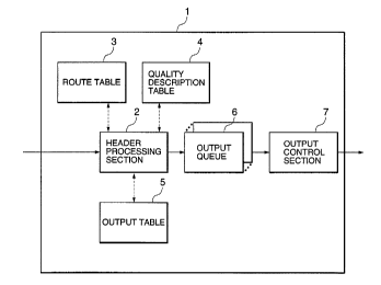
Fig. 1 is a block diagram showing the arrangement of a node
CA 02337395 2001-O1-12
' - 35 -
apparatus according to the first embodiment of the present
invention. A node apparatus 1 according to the first embodiment
is an apparatus for setting a plurality of VCs having di-.fferent
qualities with respect to an adjacent node apparatus (not shown)
and transmitting packets over the VCs while guaranteeing their
qualities. The node apparatus 1 is comprised of a header
processing section 2 for processing an incoming packet and
determining an output queue and output VC, a route table 3 for
determining an output destination, a quality description gable 4
for determining a quality class, an output table 5 for selecting
an output queue and output VC on the basis of an output
destination and output VC, a plurality of output queues 6 for
which appropriate qualities are respectively set, and an output
control section 7 far outputting a packet from the output; queue
6 to an output VC in accordance with the quality set in each
output queue 6. In this case, the output queues 6 equal in
number to at least the quality classes a.re prepared in units of
output destinations.
As shown in, for example, Fig. 2, in the route table 3,
output destinations are defined in advance in correspondence
with pairs of destination addresses and their mask lengths. In
this case, a mask length indicates how many bits from the: start
of the destination address are effective.
The quality description table 4 is configured, for example,
as shown in Fig. 3 when the IPv4 (IP version 4) protocol is used
as a third-layer protocol. Referring to Fig. 3, in this quality
description table 4, quality classes are defined in
correspondence with combinations of virtual dedicated network
CA 02337395 2001-O1-12
- 36 -
numbers, destination addresses/mas:k lengths, source
addresses/mask lengths, fourth-layer protocols/source port
numbers, and destination port numbers. In this quality
description table 4, in each entry, a_Ll the fields need not
always be filled in, and a plurality of blank fields are allowed.
Each blank field is interpreted as information coinciding with
any value in a search in the quality description table 4. This
allows flexible quality guarantees such as a quality guarantee
for each flow, a quality guarantee for each terminal, a quality
guarantee for each LAN, a quality guarantee for each virtual
dedicated network number, a quality guarantee based on each port
number, and a combination of these quality guarantees. In
addition, by increasing the unit of quality guarantee; tree size
of the quality description table 4 can be decreased. ~3everal
examples of operation using this table will be described below.
(a) When a specific flow is to be defined, all the fields
in the entry corresponding to the flow are filled in.
( b ) When a quality is to be dc:f fined between specif is
terminals, the fourth-layer protocol/source port number field
and destination port number field in the corresponding entry are
left blank.
(c) When a quality is to be defined with respeclt to a
traffic sent out from a specific terminal, the fourth-layer
protocol/source port number field, destination port number field,
destination address/mask length field in the corresponding entry
are left blank.
( d ) When a quality is to be def ine~d between specific.; LANs ,
the fourth-layer protocol/source port number field and
I!I!
CA 02337395 2001-O1-12
- 37 -
destination port number field in the corresponding entry are
left blank, arid the mask lengths of thE: addresses held by the
respective LANs are set in the source address mask length field
and destination address mask length field, respectively.
(e) When a quality is to be defined with respeclt to a
specific virtual dedicated network, all fields other than the
virtual dedicated network number field in the corresponding
entry are left blank.
(f) When a quality is to be defined with respect to a
specific application in a specific virtual dedicated neawork,
the source address/mask length field and destination
address/mask length field in the corresponding entry are left
blank, and the values to be used b:y the application are
respectively set in the fourth-layer proi~ocol/source port number
field and destination port number field.
Priorities are assigned to the respective fields ~of the
quality description table 4. In this embodiment, the highest
priority is assigned to "virtual dedicated network number"; the
second highest priority, to "destination address/mask length";
the third highest priority, to "fourth-layer
protocol/destination port number"; the fourth highest priority,
to "source address/mask length"; and the fifth highest priority,
to "fourth-layer protocol/source port number".
Fig. 3 shows an example of the quality description table 4
using the IPv4 (IP version 4) protocol as a third-layer protocol.
However, this apparatus may incorporate quality description
tables having different arrangements :in correspondence with
different third-layer protocols. For example, a quality
CA 02337395 2001-O1-12
° - 38 -
description table based on the IPv9: protocol, a quality
description table based on the IPv6 protocol, and the like may
be used. When quality description gables are respectively
prepared for different third-layer protocols in this mariner, a
field indicating the type of third-layer protocol is af.ded to
each quality description table. In the case of the quality
description table based on the IPv6 protocol, a flow label field
in the IPv6 protocol and the like are added to the fields shown
in Fig. 3.
In the output table 5, as shown i:n, for example, 1?ig. 4,
the number of the output queue 6 to tie used and the number
(VPI/VCI) of VC to be used in output operation are defined in
correspondence with each pair of an output destination and
quality class.
The operation of the first embodiment will be described
next.
When a packet arrives at the node apparatus 1 of the; first
embodiment through a given input VC, the operation shown in the
flow chart of Fig. 5 is performed.
O Step S1: First of all, the header processing section 2
performs necessary processing such an error check on the packet
and updating, and also discards a packet as needed. If the
packet is associated with routing, the header processing section
2 performs necessary processing such as updating the routE: table
3. If the packet is discarded or terminated by this node, the
processing in step S2 and the subsequent steps described. below
is not performed.
O Step S2: The header processing section 2 then searches the
CA 02337395 2001-O1-12
_ 39 _
route table 3 in Fig. 2 on the basis of the destination address
contained in the header of the packet ito determine the output
destination of the packet. In this case, the destination
address contained in the header is cornpared with destination
addresses in the route table 3 within t:he portions indicted by
the mask lengths in the route table 3. If a plurality of
addresses are searched out, an output de:~tination is obta.i_ned by
selecting one of the addresses which has the greatest mask
length.
O Step S3: The header processing section 2 extracts the
destination address, destination port number, source address,
source port number, and fourth-layer protocol contained in the
header of the packet, and determines a virtual dedicated network
number, thereby searching the quality description table, 4 in
Fig. 3 by using these values. For example, this search i.s made
as follows.
(a) An entry in which all the fields other than blank fields
match the above values is searched out. In this case, matching
of source addresses and destination addLresses is performed by
comparing only the portions indicated 'by the respective mask
lengths. If only one entry is found out, the quality class in
the entry is set as the quality class of 'the packet.
(b) Assume that a plurality of entrie:~ are found out in (a)
described above. In this case, of the p7Lurality of entriea, any
entry in which a match is obtained in a field with a higher
priority is selected. If only one entry is selected, the
quality class in the entry is set as the quality class of the
packet.
CA 02337395 2001-O1-12
, ~ - 40 -
(c) If a plurality of entries are selected in (b) described
above, any entry in which the mask length of the destination
address is the greatest is selected. If only one entry is
selected, the quality class in the entry is set as the quality
class of the packet.
(d) If a plurality of entries are selected in (c) described
above, an entry in which the mask length of the source address
is the greatest is selected. A quality class for the packet is
then obtained from the selected entry.
O Step S4: The header processing section 2 obtains an output
queue number and output VC number by looking up the output table
5 in Fig. 4 on the basis of the output destination obta:fined in
step S2 and the quality class obtained in step S3.
O Step S5: The header processing section 2 stores the output
queue number obtained in step S4 in the output queue 6.
Operation to be performed when a packet is output from the
node apparatus 1 of the first embodiment will be described next.
For example, as indicated by the flow chart of Fig. 6, in
outputting a packet, the output control section 7 selects one of
the plurality of output queues 6 so as to satisfy the quality
set for each output queue 6 (step S11), extracts one packet from
the head of the selected output queue 6 ( step S12 ) , and outputs
the packet to the output VC determined in step S4 in Fig. 5
(step S13).
(Second Embodiment)
Fig. 7 is a block diagram showing the arrangement of a node
apparatus according to the second embodiment of the present
invention. A node apparatus 10 of this embodiment is the same
CA 02337395 2001-O1-12
- 41 -
as the node apparatus of the first embodiment except that the
apparatus 10 has one output table 12 in place of the route table
3, quality description table 4, and output table 5 in Fig. 1.
Fig. 8 shows an example of the arrangement of the output
table 12. The output table 12 is obtained by integrating the
route table 3, quality description table; 4, and output table 5
in the first embodiment. In this embodiment, output queue
numbers and output VC numbers are defined in correspondence with
combinations of virtual dedicated network numbers, dest~_nation
addresses/mask lengths, source addresses/mask lE:ngths,
fourth-layer protocols/source port numbers, and destination port
numbers.
As in the quality description i~able 4 in the first
embodiment, priorities are assigned to the respective fields in
the output table 12. In this embodiment, however, the highest
priority is assigned to the destination address/mask length
field because an output destination must be determined by using
the output table 12. The remaining fields are as signed
priorities in the same manner as in the first embodiment. That
is, the second highest priority is assigned to the virtual
dedicated network number field; the third highest priority, to
the fourth-layer protocol/destination port number field; the
fourth highest priority, to the source address/mask length
field; and the fifth highest priority, to the fourth-layer
protocol/source port number field. In lthis output table 12 as
well, all the fields need not always be filled in, and a
plurality of blank fields are allowed.
The operation of the second embodiment of the present
CA 02337395 2001-O1-12
i
y - 42 -
invention will be described next.
When a packet arrives at the node apparatus 10 of the
second embodiment through a given input VC, the operation shown
in the flow chart of Fig. 9 is performed.
O Step 521: First of all, the header processing section 11
performs necessary processing such an error check on the packet
and updating, and also discards a packet as needed. If the
packet is associated with routing, the header processing section
11 performs necessary processing such as updating the
destination address, output queue numbez:, and output VC number
in the output table 12. If the packet is discarded or
terminated by this node, the processing in step S22 and the
subsequent steps described below is not performed.
O Step 522: The header processing section 11 then searches the
output table 12 by using the same search. scheme as that f:or the
quality description table 4 in the first embodiment to obtain an
output queue number and output VC number. More specifically,
the header processing section 11 exitracts the dest:i.nation
address, destination port number, source address, source port
number, and fourth-layer protocol contained in the header of the
packet, and determines a virtual dedicated network number from
the number of the VC through which the packet has arrived. The
header processing section 11 then searches the output table 12
in Fig. 8 by using these values, and obtains an output queue
number and output VC number from the selected entry.
O Step 523: The header processing section 11 stores the packet
in a selected output queue 13.
The operation to be performed when the node apparatus 10
CA 02337395 2001-O1-12
- 43 -
outputs a packet in the second embodiment is the same as the
node apparatus 1 in the first embodiment. That is, an output
control section 14 outputs a packet from each output queuE: 13 to
a corresponding output VC in accordance with a quality set for
each output queue 13.
Fig. 10 shows the format of data in each embodiment of the
present invention. IP-related processing is performed for a
packet segmented into cells by using AAL5, with a header
identifying the packet being added thereto . More specifically,
an AAL5 frame consisting of an 8-byte header, a packet
consisting of 65,536 bytes at maximum, a PAD, and an 8-byte AAL5
trailer is divided in units of 48 bytes. Thus, the frame is
segmented into a plurality of cells with the respective divided
portions being payload portions. In this case, the cell header
of each cell contains a VPI/VCI. The start cell contains an
8-byte AAL5 header, and hence contains an IP header including a
destination IP address. The final cell contains an 8-byte AAL5
trailer, and hence contains the CRC value of the AAL5 frame. In
addition, the final cell is identified by its payload type (PT).
Although the header indicated by RFC 1483 is a typical header,
an implementation without any header is also conceivable.
(Third Embodiment)
Fig. 11 is a block diagram showing the arrangement of a
node apparatus according to the third ennbodiment of the present
invention. A node apparatus 30 of the third embodiment is an
apparatus for setting a plurality of VCs having different
qualities with respect to an adjacent node apparatus (not shown)
and transmitting packets segmented into cells over the VCs while
CA 02337395 2001-O1-12
- 44 -
guaranteeing their qualities. This apparatus is comprised of a
header processing section 31 for processing an inooming packet
and determining an output queue and output VC, a route table 32
for determining an output destination, a quality description
table 33 for determining a quality class, an output table 34 for
selecting an output queue and output VC on the basis of an
output destination and quality class, a plurality of packet
queues 35, a plurality of output queued 35 for which proper
qualities are respectively set, and an output control section 37
for outputting cells constituting a packet from each output
queue 35 in accordance with the quality set therefor. In this
case, the output queues 35 equal in number to at least the
quality classes are prepared in units of output destinations.
As in the second embodiment, in th.e node apparatus 30 of
the third embodiment, the present invention is applied to an ATM
switch capable of performing quality control for each output
queue. A quality guarantee on the packed level is provided by
using a quality guarantee mechanism on the cell level which the
ATM switch has. That is, the output queues 35 and output
control section 37 used in the ATM switch are used.
The node apparatus 30 of the third embodiment is configured
to segment a packet into cells according to the scheme shown in
Fig. 10 and transfer them between nodes. This apparatus keeps
processing the packet segmented into cells without reassembling
them into the packet. For this reason, a packet reassembling
section 21 and packet segmenting section 26 are omitted from the
third embodiment. The packet queues 35 a.re added as constituent
elements instead. The packet queues 35 are queues each for
i'i,'
CA 02337395 2001-O1-12
- 45 -
storing cells corresponding one packet, and prepared for the
respective input VCs. When packets received from different VCs
are to be output to a single VC, the packet queues 35 prevent
cells constituting different packets from being nested.
The route table 32, quality description table 33, and
output table 34 in the third embodiment have the: same
arrangements as those in the first embodiment, and are
respectively configured as shown in, for example, Figs. 2, 3,
and 4.
The operation of the third embodiment will be described
next.
When a cell of a packet arrives at the node apparatus 30 of
the third embodiment through a given input VC, the operation
shown in the flow chart of Fig. 12 is performed. Note that
incoming cells are directly sent to the header processing
section 31 without being assembled into a. packet.
0 Step 551: The header processing section 3l determines
whether the incoming cell is the start .cell of the packed. In
this determination, since the final cell of an AAr.5 frame is
identified by its payload type (PT) , for. example, the fo:Llowing
method can be used. Flags that are set when final cells are
detected are managed for the respective input VCs. When such a
flag is set, and a cell is then receiveii from the corresponding
input VC, the received cell is determined as the start cell. If
the incoming cell is the start cell, sin<:,e the cell contains the
header of the packet, the processing i.n steps S52 to S55 is
performed, and then the flow advances to step 556. If the cell
is not the start cell, the.flow advances to step 556.
iv
CA 02337395 2001-O1-12
_ 46 _
O Steps S52 to 555: Processing similar to that in steps S1 to
S4 in the first embodiment is performed to obtain an output
queue number and output VC number.
O Step 556: The incoming cell is stored in the packet queue 35
corresponding to the input VC through which the cell has arrived.
O Step 557: It is checked on the basis. of the payload i:ype of
the cell whether the incoming cell is the final cell.
O Step 558: If the incoming cell is the final cell, all the
cells of one packet are simultaneously moved from the packet
queue 35 to the output queue 36 corresponding to the output
queue number obtained in step S55.
In outputting cells constituting a packet from the node
apparatus 30 of the third embodiment, the, output control section
37 extracts cells from each output queues 36 in accordance with
the quality set therefor, and outputs them to an output VC
corresponding the output VC number obtained in step S55. In
this case, the VPI/VCI of each cell is converted into an output
VC number (VPI/VCI). In this case, according to the third
embodiment, since data are read out from the output queue 36 in
units of cells instead of packets, if: cells from different
output queues 36 are output to a single VC, the cells
constituting different packets may be nested. For this reason,
in this embodiment, the respective output queues 36 are; in a
one-to-one correspondence with output 'JCs, and cells from a
plurality of output queues 36 are not output to a single output
VC.
On the other hand, if the cells that have arrived at the
node apparatus 30 are not cells constituting a packet but are
i:i,
CA 02337395 2001-O1-12
_ 47 _
general ATM cells, the cells are subjected to processing similar
to that performed by using a general ATM switch.
(Fourth Embodiment)
Fig. 13 is a block diagram showing the arrangement of a
node apparatus according to the fourth ernbodiment of the present
invention. A node apparatus 40 of this embodiment is cornprised
of a plurality of input buffer sections 42, a cell switch
section 41, and a plurality of output buffer sections 43., each
of which has the same arrangement as that in the node apparatus
30 of the fourth embodiment shown in Fig. 11. Each output
buffer section 43 is comprised of a plurality of packet queues
51, a plurality of output queues 52, an output control section
53, and a header processing section ;i4. The input buffer
sections 42 and output buffer sections 43 are prepared in units
of physical lines.
In the fourth embodiment, packet queues 48 in each input
buffer section 42 are used to multiplex packets that: have
arrived from different VCs on a single physical line to a single
output VC, and the packet queues 51 in each output buffer
section 43 are used to multiplex packets that have arrived at
VCs on different physical lines to a sing:Le output VC.
The packet queues 48 in each input: buffer section 42 are
prepared by the number of input VCs of the input buffer section
42, and output queues 49 are prepared by the number of output
VCs of the node apparatus 40. The packet queues 51 in each
output buffer section 43 are prepared by the number of input
buffer sections 42 for each output VC of the output buffer
section 43. The output queues 52 are prepared f.or the
lilt
CA 02337395 2001-O1-12
a ° _
respective output VCs of the output buffer section 43.
In the node apparatus 40 of this embodiment as well, the
present invention is applied to an ATM switch capa'hle of
performing quality control for each output queue. A quality
guarantee on the packet level is provided by using a quality
guarantee mechanism on the cell level which the ATM switch has .
That is, the output queues 49 and 52, output control sections 49
and 53, and cell switch section 41 used in the ATM switch are
used.
A route table 45, quality description table 46, and output
table 47 in this fourth embodiment have 1'~~he same arrangements as
those in the first embodiment, and are respectively configured
as shown in, for example, Figs. 2, 3, an~i 4. In this embodiment
as well, a packet is segmented into cells according to the
scheme shown in Fig. 10, and the cells are transferred between
nodes.
The operation of the fourth embodiment will be described
next.
The operation of the input buffer sE:ction 42 is the same as
that of the node apparatus 30 in the fourth embodiment except
that cells are not output to an output VC but are output to the
cell switch section 41. In outputting a cell, the output
control section 50 outputs it upon adding the input buffer
number (uniquely specifying the input lbuffer section) of the
cell source.
The cell switch section 41 switches the cell output from
each input buffer section 42 to the proper output buffer section
43 in accordance with the output destination of the cell.
CA 02337395 2001-O1-12
- 49 -
The operation of the output buffer section 43 will be
described next . When a cell arrives from any one of the input
buffer sections 42 through the cell switch section 41, the
header processing section 54 of the output buffer section 43
temporarily stores the incoming cell _Ln the packet queue 51
corresponding to the output VC specified by the VPI/VCI in the
cell and the source input buffer section 42 added to thf: cell,
as shown in the flow chart of Fig. 14 (step S61). More
specifically, cells that have arrived from the same input buffer
section 42 and constitute packets having the same output
destination and the same quality class are stored in the same
packet queue 51 corresponding to that output destination and
input buffer section, whereas cells that have arrived from the
different input buffer sections 42 and constitute packets having
the same output destination and the same quality class are
stored in the different packet queues 51 in units of input
buffer sections 42. If the currently stored cell is the final
cell of the corresponding packet (step S62), the cells of all
the packets in the packet queue 5~1 are moved to the
corresponding output queue 52 (step S63). In this case, the
corresponding output queue 52 is an output queue corresponding
to the output VC specified by the VPI/'JCI in the cell of the
packet. With this operation, packets that have arrived from the
different input buffer sections 42 and: have the same output
destination and the same quality class are multiplexed to the
same output queue 52.
The output control section 53 extracts cells from each
output queue 52 in accordance with the quality set therefor, and
CA 02337395 2001-O1-12
. ' - 50 -
outputs them to an output VC corresponding to the output queue.
As described above, in the fourth embodiment, in a sense, a
pair of each output queue 52 of each output buffer section 43
and a corresponding output queue 49 o:E a corresponding input
buffer section 42 constitute one virtua~'_ output queue. 'The sum
of qualities of the corresponding output queues 49 of each input
buffer section 42, i.e., a quality required to satisfy all the
qualities set for the corresponding output queues 49 of each
input buffer section 42, is set for the output queue 52 of the
output buffer section 43.
In the fourth embodiment as well,, the respective output
queues are in a one-to-one correspondence with output VCa, and
cells are not output from a plurality of output queues to a
signal output VC. If the cells that have arrived at the node
apparatus 40 are not cells constituting a packet but are general
ATM cells, the cells are subjected to processing similar ito that
performed by using a general ATM switch.
The present invention is not limited by the ahnvP
embodiment alone, and various changes can be made. For example,
when priorities are assigned to the respective entries of the
above quality description table, and the table is to be se~rehed,
any entry in which all the fields other than blank fields match
an incoming packet is selected. If a plurality of entries are
selected, an entry with the highest priority may be selected.
(Fifth Embodiment)
Fig. 15 is a block diagram showin~~ the arrangement: of a
node apparatus according to the fifth embodiment of the present
invention. A node apparatus 100 of this embodiment is comprised
lili
CA 02337395 2001-O1-12
_ > _ 51 _
of a header processing section 102 fo:r performing ATM header
processing for input cells, sorting thE: cells into ATM and IP
cells, and storing them in queues, a VC table 103, an IP
processing section 104 for processing packets, an IP route table
105, packet queues 106 each for holding cells constituting a
packet until cells corresponding to one packet are stored,
output queues 107 for holding cells to be output to output VCs,
an output section 108 for outputting cells to an output VC, and
an output table 109. In this case, the packet queues :L06 are
prepared by at least the number of input VCs set for IP of the
input VCs of the node apparatus 1. The output queues :L07 are
prepared by at least the number of output VCs of the node
apparatus 100.
In the IP route table 105, for example, as shown in fig. 16,
the number of the output queue 107 is defined as route
information in advance in correspondence with each pair of a
source IP address and its mask length. The mask length
indicates how many bits from the start of the destination IP
address are effective.
For example, as shown in Fig. 17, t:he VC table 3 contains,
for each input VC (i.e., each VPI/VCI), an IP identification
flag for identifying the corresponding input VC as a VC set for
IP or ATM, a start cell identification flag indicating whether
the input cell is the start cell of the packet or not, an output
destination queue indicating the first storage location of the
input cell, a movement destination queue indicating the
destination of the packet after IP proce.ssing, CRC1 for :storing
an interim value for a CRC check, CRC2 for storing an interim
i i i'
CA 02337395 2001-O1-12
- 52 -
value for CRC re-calculation, and a discard flag indicating that
the packet is being discarded. For an. input VC set for ATM,
however, the output queue number of a predetermined output queue
107 is written in "output destination queue", and "movement
destination queue", "CRC1", and "CRC2" are not used. For an
input VC set for IP, the number o:f a packet queue 106
corresponding to the input VC is written, and the number of a
predetermined output queue 107 is written in "movement
destination queue". In this case, in the VC table 103,
necessary values are set in all the source VPI/V(:I, IP
identification flag, and movement destination queue fields in
all the entries before the table is used, while the start cell
identification flag field is initialized to true; the movement
destination queue field, to the NULL value, the CRC1 and CRC2
fields, to 0, and the discard flag field, to false.
For example, as shown in Fig . 18 , i_n the output table 109 ,
for each output queue number (i.e., each output queue 7), a
quality parameter for the output queue, a transmission VI?I/VCI,
and output destination information are defined in advance.
The operation of the node apparatus 1 according to the
fifth embodiment will be described. Operation to be performed
when a cell has arrived at the node apparatus 100 from a given
input VC will be described first.
As shown in the flow chart of Fig. :L9, when a cell arrives,
the header processing section 102 searchEa the header processing
section 102 with the VPI/VCI contained in the input cell, and
checks the discard flag and start cell identification flag in an
entry having the same VPI/VCI (step F1). Note that all the
I 411
CA 02337395 2001-O1-12
s - 5 3
discard flag, start cell identification flag, IP identif.ication
flag, output destination queue, movement destination queue, CRC1,
CRC2, and discard flag to be referred to in the subsequent
processing are those in the entry in the; VC table 103 which has
the same VPI/VCI.
As a result of the above reference, if the discard flag is
true, and the cell is not the start cell (the start cell flag is
false), the input cell is discarded (step F17), and the
processing is terminated. If the input cell is the start cell
(the start cell flag is true) or the di:ocard flag is false, the
header processing section 102 checks the. IP identification flag
in the VC table 103 (step F2). If the IP identification flag
indicates ATM, the input cell is stored in the output queue 107
indicated by the output destination queue in the VC table 103
(step F20). If the IP identification flag indicates IP, the
input cell is sent to the IP processing section 104, and the
subsequent processing is performed.
First of all, CRC1, i.e., a check CRC interim value, is
updated on the basis of the input cell (step F3). More
specifically, the initial value of CRC1 in the VC table 3 is
updated with the remainder of the quotient obtained by dividing
the bit string, formed by adding the value (initial value: 0) of
CRC1 of the VC table 103 to the head of the payload ~of the
current cell, by a predetermined value. The header processing
section 102 checks the start cell identification flag of the VC
table 103 again ( step F4 ) . If this f:Lag is true, since the
current cell is the start cell, the header processing section
102 executes processing to be performed f:or the start cell. alone
CA 02337395 2001-O1-12
Y - 54 -
( steps F5 to F10 ) . The flow then advances to step F11. If the
start cell identification flag is false, since the current cell
is not the start cell, the flow skips steps F5 to F'10 and
advances to step F11.
In processing the start cell, the header processing section
102 resets the start cell identification flag in the V~ table
103 to false, and also resets the discard flag to false
temporarily (step F5). The header processing section 102 checks
the IP header contained in the start cell (step F6). If an
error is detected, the discard flag is changed to true to
discard cells that will arrive afterward (step F8), and the
current start cell is discarded (step F1'7), thus terminating the
processing. If no error is detected, the header processing
section 102 searches the IP route table 105 by using the
destination IP address contained in the start cell as a key to
acquire an output queue number ( step F7 ) , and writes the output
queue number in the movement destination queue in the VC; table
103 (step F9). The header processing section 102 then performs
necessary IP header updating (step F10). In this case,
necessary IP header updating is to decrease TTL (Time Tcr Live)
by one and update the checksum of the IP header in, for example,
IP version 4. In searching the IP route table 105 in step F7,
the destination IP address contained in the start cell is
compared with the destination IP address; in the IP route. table
105 within the portion indicated by the mask length in the IP
route table 105. If the destination IP address matches a
plurality of destination IP addresses, a. destination IP address
having the greatest mask length is selected to obtain an output
i;i
CA 02337395 2001-O1-12
- 55 -
queue number. In this embodiment, if there is no match of the
destination IP address, the discard flag is changed to true
(step F8), and the start cell is ,disc;arded (step F17), thus
terminating the processing.
The IP processing section 104 updates CRC2 for all the
cells including the start cell, i.e., the CRC interim value for
re-calculation. More specifically, the .initial value of CRC2 in
the VC table 103 is updated with the remainder of the quotient
obtained by dividing the bit sting, formed by adding the value
of CRC2 in the VC table 103 to the head of the payload (after IP
header updating in the start cell) of the current cell, by a
predetermined value. The reason why the CRC value is
re-calculated in this manner is that the IP header was updated
in step F10, and TTL and the checksum of the IP header were
changed.
If the payload type of the current cell does not indicate
that the cell is the final cell of an AAh5 frame (step F1:?), the
current cell is stored in the packet queue 106 indicated by the
output destination queue in the VC table 103 (step F20).
If the current cell is the final. cell, the start cell
identification flag in the VC table 103 is changed to true to
indicate that the cell that will arrive next is the start cell
(step F13). The calculated value CRC2 (:cored in CRC2 in the VC
table 103 ) is written back to the CRC fiE:ld of the final cell of
the AAL5 frame (step F14) and stored in the packet queue 106
indicted by the output destination queue in the VC table 103
(step F15). If checked CRC1 (stored in CRC1 in the VC table 3)
indicates a CRC error in the AAL5 frame ( step F16 ) , the overall
CA 02337395 2001-O1-12
- 56 -
packet output to the packet queue 106 i.s discarded (step F19).
Otherwise, the overall packet is moved to the output queue 107
in accordance with the designation by t:he movement destination
queue in the VC table 103 (step F18).
Operation to be performed when cells are output from the
node apparatus 100 in the fifth embod~inent will be described
below. As shown in the flow chart of Fig. 20, in outputaing a
cell, the output section 108 selects a proper output queue from
the plurality of output queues 107 (step F31). The node
apparatus 100 extracts one cell from the head of this output
queue and changes the VPI/VCI of the cell (step F32), and then
outputs the cell to an output VC set for the output queue (step
F33). More specifically, in selecting .a proper queue from the
plurality of output queues 107 in step F31, the output section
108 refers to a quality parameter for each output queue 107 in
the output table 9 in Fig. l8 and selects an output queue that
satisfies the defined quality. In addition, in changing the
VPI/VCI in step F32, the output section 108 converts it to a
transmission VPI/VCI corresponding to the output queue defined
in the output table 109. In outputting a cell in step F33, the
output section 108 outputs the cell the output VC indicated by
the output information in the output table 109.
In the fifth embodiment, when different packets having the
same destination IP address are input from different input VCs
after they are segmented into cells, since they have the same
destination IP address, the same output queue number is obtained
in searching the IP route table 105 in Fig. 16, and these
packets are finally stored in the same output queue 107. Since
CA 02337395 2001-O1-12
_ 57 _
the same output queue number is obtained, the cells are
converted into the same VPI/VCI in the output table 109 in
Fig. 18, and this VPI/VCI is output t:o the same output VC.
However, since the cells constituting the respective IP packets
are received through different input VCs, they are temporarily
stored in different packet queues 106, respectively, and cell
corresponding to one packet are moved together to the same
output queue 107 to be sequentially output in units of cells
from the start cell. For this reason, there is no chance that
cells constituting a given packet are inserted in a cell- group
forming another packet on the same output VC. Even if,
therefore, packets that have arrived fx:om different input VCs
are output to a single output VC, the packets segmented into
cells can be easily reassembled on the receiving side. As
described above, in the node apparatus 100 of the fifth
embodiment, when packets that have arrived from different. input
VCs are to be output to the same route, they can be multiplexed
on the same VC.
According to the fifth embodiment, the IP processing
section 104 incorporates a means (equival.ent to steps F3 and F16
in Fig. 19) for performing a CRC check on an AAL5 frame while
the cells are kept segmented without forming packets from the
AAL5 frame, a means (equivalent to step F10 in Fig. 19) for
updating necessary information such as the TTL field and IP
checksum field in a packet, and a means (equivalent to steps F11
and F14 in Fig. 19) for re-calculating and setting a CRC value
for the AAL5 frame without forming packets from the frame. With
this arrangement, in addition to de:~tination determination
CA 02337395 2001-O1-12
- 58 -
processing, the IP processing section 104 can perform a packet
check and IP-related processing for a TTL field and IP checksum
field without reassembling cells into a packet.
According to the fifth embodiment, with the use of the
header processing section 2, not only an IP traffic but also a
general ATM traffic can be handled.
The IP multicast function of the node apparatus 100 of the
fifth embodiment will be described next. In the node apparatus
100 of the fifth embodiment, if a destination IP address in the
IP route table 105 is an IP multicast address, an output. queue
for ATM cell multicast is set in the output queue number, and a
transmission VPI/VCI and output destination information a.re set
for a plurality of routes in correspondence with the
corresponding output queue number in the output table 109 in
Fig. 18. For this reason, after the cells of a packet having a
destination IP address which is an IP multicast address are
moved to the output queue 107 for muli~icast, converted cells
having different VPI/VCIs are multicast t:o the respective routes
in steps F32 and F33 in Fig. 20 when they are output from the
output queue 7. That is, this embodiment uses the cell copy
function of the ATM switch instead of: copying a packet in
implementing an IP multicast function.
(Sixth Embodiment)
Fig. 21 is a block diagram showing the arrangement of a
node apparatus according to the sixth embodiment of the present
invention. A node apparatus 110 of this embodiment includes a
plurality of input buffer sections 112, a plurality of output
buffer sections 113, and a cell switch section 111 for
CA 02337395 2001-O1-12
9..
- 59 -
transferring a cell output from an arbitrary input buffer
section 112 to an arbitrary output buffer section 113.
All the input buffer sections 112 have the same arrangement
and are prepared in units of physical lines. Each input buffer
section 112 is comprised of a header processing section 114 for
performing ATM header processing for input cells, sorting the
cells into ATM and IP cells, and storing them in queues, a VC
table 115, an IP processing section 116 for processing packets,
an IP route table 117, packet queues 118. each for holding cells
constituting a packet until cells corrEaponding to one packet
are stored, output queues 119 for holding cells to be output, an
output section 125 for output ing cells to the output buffer
section 113 through the cell switch secition 111, and an output
table 127. In this case, the packet queues 118 are prepared by
at least the number of input VCs set for IP of the input VCs of
the input buffer section 112. The output queues 119 are
prepared by at least the number of output VCs of the node
apparatus 100.
For example, as shown in Fig. 16, in the IP route table 117,
the number of the output queue 119 is defined as route
information in correspondence with each pair of a destination IP
address and its mask length.
For example, as shown in Fig. 22, the VC table 115 contains,
for each input VC (i.e., each VPI/VCI), an IP identification
flag for identifying the corresponding input VC as an input VC
set for IP or ATM, a start cell identification flag indicating
whether the input cell is the start cel7_ of the packet or riot,
an output destination queue indicating the first storage
i;i
CA 02337395 2001-O1-12
- 60 -
location of the input cell, a movement destination queue
indicating the movement destination of the packet after IP
processing is complete, CRC1 for storing an interim value for a
CRC check, and a discard flag indicating that the packet is
being discarded. Note that in an input; VC entry set far ATM,
the output queue number of a predetermined output queue 119 is
written in the output destination queue field, and the movement
destination queue and CRC1 fields are not used. In an input VC
entry set for IP, the number of the packet queue 118
corresponding to the input VC is written in the output
destination queue field, and the number of a predetermined
output queue is written in the movement destination queue field.
This VC table 115 is identical to the VG table 103 in the fifth
embodiment except that no CRC2 is prepared. This is because in
this embodiment, CRC re-calculation is performed by using the
output buffer 113 instead of the input buffer section 112 to
realize load distribution. Before operation, all necessary
values are set in the source VPI/VCI, IP identification flag,
and output destination queue fields in all the entries, while
the start cell identification flag is initialized to true; the
movement destination queue, to a NULL value, CRC1, to 0; and the
discard flag, to false.
For example, as shown in Fig. 23, for each output queue
number ( i. a . , each logic link to the cell_ switch section 1.11 ) , a
quality parameter for the output queue, internal identifier, and
output destination information are defined. In general, with
regards to VCs set for ATM, the internal identifier can uniquely
specify an output VC set for ATM. With regards to VCs set for
CA 02337395 2001-O1-12
- 61 -
IP, in the sixth embodiment, the internal identifier can
uniquely specify a pair of an output V'C and the input buffer
section 112 to which a cell is output.
All the output buffers 113 have the same arrangement, and
are prepared for, for example, the respective physical lines.
Each output buffer 113 is comprised of a header processing
section 120 for performing ATM header processing for an input
cell, sorting the cells into ATM and IP cells, and storing them
in queues, a VC table 121, a CRC re-calculation section 122
serving as an IP processing section on the output buffer section
side, packet queues 123, output queues 124, an output section
126, and an output table 128. In this case, the packet queues
123 are prepared by at least the number of input buffer sections
112 for the respective output VCs for :CP in the corresponding
output buffer 113. The output queues 1.24 are prepared by the
number of output VCs of the corresponding output buffer 113.
For example, as shown in Fig. 24, in the VC table 121, for
each internal identifier (each internal identifier for ATM and
each internal identifier for IP), an IP identification flag for
identifying the internal identifier as an internal identifier
set for IP or ATM, an output destination queue indicating the
first storage location of the input cell, a movement destination
queue indicating the movement destination of the packet upon
completion of IP processing, and CRC2 for storing an interim
value for CRC re-calculation. The output queue number of a
predetermined output queue 124 is written in the output
destination queue field corresponding to the internal identifier
set for ATM, and the movement destination queue and CRC2 fields
CA 02337395 2001-O1-12
- 62 -
are not used. In the output destination queue field
corresponding to the internal identifier set for IP, the number
of the packet queue 123 corresponding to the output VC and input
buffer section uniquely specified by the: internal identifier is
written, and the number of a predeterm.i_ned output queue 24 is
written in the movement destination queue field. This V(: table
121 is identical to the VC table 103 in the fifth embodiment
except that the table 121 has no start cell identification flag,
CRC1, and discard flag fields, and uses an internal identifier
in place of a source VPI/VCI. Before operation, all necessary
values are set in the internal identifier, IP identification
flag, output destination queue, and movement destination queue
fields in all entries, and CRC2 is initialized to 0. The
movement destination queue, in particular, is not changed for
each packet but is fixed in accordance with the output VC
uniquely specified by an internal identifier set for IP.
For example, as shown in Fig. 18, i.n the output table 128,
for each output queue number (i.e., each output queue 24), a
quality parameter for the output queue, a transmission VPI/VCI,
and output destination information are defined in advance.
The operation of the sixth embodiment will be described
next. Operation to be performed when a cell arrives ;at the
input buffer section 112 will be described first . At the time
of arrival of a cell, for example, the :processing shown in the
flow chart of Fig. 25 is executed. The same reference numerals
as in Fig. 19, which is the flow chart for processing at the
time of arrival of a cell in the first embodiment, denote the
same processes in the flow chart of Fig. 25. As is obvious from
CA 02337395 2001-O1-12
- 63 -
Figs. 25 and 19, the operation of the input buffer section 112
at the time of arrival of a cell is the same as the node
apparatus of the first embodiment except that CRC2 calculation
and write are not performed. That is, if the input cell. is an
ATM cell, the cell is directly stored in a predetermined output
queue 119. If the input cell is a cell of a packet, the cell is
stored in the packet queue 118 preset for each input VC, while
CRCl calculation, an IP header cheek on a start cell,
determination of an output queue by a search in the IP route
table 117, IP header updating, a CRC1 check at the time of
processing of a final cell, transfer of all cells from the
packet queue 118 to the output queue 119 in normal processing,
and the like are performed. Note that since CRC2 calculation
and write are not performed, the CRC field of the final cell of
an AALS frame transferred to the output queue 119 remains
unchanged.
The operation to be performed when an cell is to be output
from the input buffer section 112 will loe described next. For
example, as shown in the flow chart of F'ig. 26, in outputaing a
cell, the output section 25 selects a proper queue from the
output queues 119 (step F51), extracts one cell from the head of
the output queue, and changes the VPI/VC:I of the cell into the
internal identifier (step F5). The output section then outputs
the cell to the output buffer 113 set for the output queue via
the cell switch section 111 (step F53). More specifically, in
selecting a proper queue from the output queues 119 in step F51,
the output section refers to a quality parameter for each output
queue in the output table 127 to select an output queue that
CA 02337395 2001-O1-12
- 64 -
satisfies the defined quality. In addition, in changing a
VPI/VCI into an internal identifier in step F52, the VPI/VCI is
converted into the internal identifier defined in the output
table 127. In outputting a cell in the step F53, the output
section outputs the cell to the output buffer 113 indicated by
the output destination information in the output table :L27 via
the cell switch section 111.
In each input buffer section 112 in the sixth embodiment,
when packets having different destination IP addresses are
segmented into cells and input from different input VCs,, since
they have the same destination IP address, the same output queue
number is obtained when the IP route gable 117 in Fig.. 16 is
searched, and all the cells of these packets are stored in the
same output queue 119. In addition, since the same output queue
number is obtained, each VPI/VCI is converted into the same
internal identifier on the basis of tlhe output table 127 in
Fig. 23, and the cells are output to the same output buffer 113.
In addition, since cells constituting the respective packets are
input through different input VCs, the: cells are temporarily
stored in different packet queues 118 in accordance with the VC
table 115 in Fig. 22. These cells are transferred to the same
output queue 119 in units of packets, and are sequentially
output from the head of the output queue. There is therefore no
chance that in a cell group forming a given packet on the same
logic link to the cell switch section 111, cells constituting
another packet are inserted. This makeso it possible to perform
multiplexing.
The operation to be performed when a cell'arrives at the
!!n
CA 02337395 2001-O1-12
65 -
output buffer section 113 will be described next. As shown in
the flow chart of Fig. 27, at the time of arrival of a cell, in
the output buffer section 13, the header processing section 120
searches the VC table 121 in Fig. 24 by using the internal
identifier written in the cell as a key to cheek the
corresponding IP identification flag (step F41). If the IP
identification flag indicates ATM, the cell is directly stored
in the output queue 124 of the output queue number indicated by
the output destination queue in the VC table 121 (step F47).
If the IP identification flag indicates IP, the cell is
sent to the CRC re-calculation section 122, and CRC2 in the VC
table 121 is updated (step F42). That is, tYae CRC
re-calculation section 122 updates the original value of CRC2 in
the VC table 121 with the remainder of i:he quotient obtained by
dividing the bit string, formed by adding the value (:initial
value: 0) of CRC2 of the VC table 121 to the head of the payload
of the current cell, by a predetermined value. It is then
checked on the basis of the payload type whether the cell is the
final cell of the packet (step F43). If it is determined that
the cell is not the final cell, the cell is stored in the packet
queue 123 of the queue number indicated by the output
destination queue in the VC table 121 (step F47), and the
processing is terminated: If it is determined that the cell is
the final cell of the packet, re-calculated CRC2 (stored in the
VC table 121) is written in the CRC field of the AAL5 franne, and
CRC2 on the VC table 121 is reset (st:ep F44). The cell is
stored in the packet queue 123 in accordance with the output
destination queue in the VC table 121 (step F45). One entire
CA 02337395 2001-O1-12
- 66 -
packet in the packet queue 123 is moved to the output queue 124
of the queue number indicated by the movement destination queue
in the VC table 121 (step F46). Note that since the movement
destination queue in the VC table 121 is fixed in accordance
with the output VC uniquely specified by the internal identifier
set for IP, even cells that have arrived from different: input
buffer sections 112 (i.e., cells with different internal
identifiers) are stored in the same outpmt queue 124 as long as
the same output VC is set.
The operation to be performed when a cell is to be output
from the output buffer section 13 will be described next ., This
operation is basically the same as that of the node apparatus of
the fifth embodiment, and is executed according to, for example,
the procedure indicated by the flow charm of Fig. 20. In a step
similar to the step F32 in Fig. 20, the, internal identifier is
converted into the transmission VPI/VCI defined in the output
table 128.
Note that as another implementation of this embodiment, an
implementation using the VPI/VCI of an output VC instead of an
internal identifier is conceivable. In this case, when a cell
is to be output from the input buffer section 112, the VPI/VCI
of the cell to be output is converted into the VPI/VCI of an
output VC, and an input buffer number (uniquely identifying an
input buffer section) is added to the cell. The resultant cell
is then output to the output buffer section 113 via the cell
switch section111. The table 121 of the output buffer
VC
section 113 referredto by using combination of the VPI/VCI
is a
of the incoming cell and the input buffer number written in the
CA 02337395 2001-O1-12
- 67 -
cell instead of an internal identifier. In addition; when the
output buffer section 113 outputs a cell, no conversion to a
VPI/VCI is performed.
As described above, in the node apparatus 110 of the sixth
embodiment, of packets output to the same VC, packets that have
arrived at different VCs of the same input buffer section 112
are multiplxed by the input buffer section 112, and packets that
have arrived at different input buffer sections 112 are
multiplexed by the output buffer section 113. Fig. 28 is a
schematic view showing this state. Of packets P1, P2, and P3
output to the same VC, the packets P1 a.nd P2 that have arrived
at different VCs of the same input buffer section 112 are
multiplexed by the input buffer section :L12, and the packets P1,
P2, and P3 that have arrived at the different input buffer
sections 112 are multiplexed by the output buffer~section :L13.
In this embodiment, CRC re-calculation is executed by the
output buffer section 113. However, this calculation may be
executed by the input buffer section 1:12. In this case, for
example , the VC table 115 is configured as shown in Fig . :L 7 , and
the VC table 121 has a CRC2 field.
(Seventh Embodiment)
Fig. 29 is a block diagram showing the arrangement of a
node apparatus according to the seventh embodiment of the
present invention. A node apparatu:~ 130 of the seventh
embodiment includes a plurality of input buffer sections 132 and
a plurality of output buffer sections 133. The node apparatus
130 also includes a cell switch section 131 for transferring a
cell output from an arbitrary input buffer section 132 to an
ii
CA 02337395 2001-O1-12
- 68 -
arbitrary output buffer section 133.
The plurality of input buffer secitions 132 have the same
arrangement and are prepared in units of physical lines. Each
input buffer section 132 is comprised of a header processing
section 134 for performing ATM header processing for input cells,
sorting the cells into ATM and IP cell_s, and storing them in
queues, a VC table 135, an IP proce;ssing section 136 for
processing packets, an IP route table 13'7, output queues 139 for
holding cells to be output, an output section 145 for outputting
a cell to the output buffer section 133 via the cell switch
section 131, and an output table 147. Unlike in the input
buffer section 112 in Fig. 21 in the sixth embodiment, there is
no packet queue. In this case, the output queues 139 are
prepared by at least the number of output VCs of the node
apparatus 130 for input VC of the input buffer section 132.
For example, as shown in Fig. 16, in the IP route table 137,
the number of the output queue 139 is defined as route
information in advance in correspondence with each pair of a
destination IP address and its mask length.
Since there is no packet queue, the VC table 135 has, for
example, an arrangement like the one shown in Fig. 17, which is
obtained by omitting the movement destination queue portion from
the arrangement shown in Fig. 22. More ;specifically, this table
contains, for each input VC (i.e., each VPI/VCI), an IP
identification flag for identifying the input VC as an input VC
set for IP or ATM, a start cell identification flag indicating
whether the input cell is the start cell of the packet, an
output destination queue indicating the storage location of the
i~i
CA 02337395 2001-O1-12
_ 69 _
input cell, CRC1 for storing an interim value for a CRC check,
and a discard flag indicating that the packet is being discarded.
For an input VC set for ATM, the output queue number. of a
predetermined output queue 119 is v~rritten in the output
destination queue field, and the CRC1 and discard flag fields
are not used. For an input VC set for IP, the number of a
predetermined output queue is written in the output destination
queue field. Before operation, all necessary values are set in
the source VPL/VCI, IP identificati.on flag, and output
destination queue fields in all entries, while the start cell
identification flag is initialized to true; CRC1, to 0, and the
discard flag, to false.
For example, as shown in Fig. 23, hike the output table 127
in the sixth embodiment, in the output table 147, fo:r each
output queue number, a quality parameter for the output queue,
internal identifier, and output destination information are
defined. In this case, with regards to VCs set for ATM, the
internal identifier can uniquely specify an output VC as in the
sixth embodiment. With regards to VCs set for IP, a pair' of an
output VC and an input VC can be uniquely specified :in the
seventh embodiment. The reason why a VC set for IP is an
identifier for uniquely specifying a pair of an input VC and an
output VC is that no packet queue is prepared for the input
buffer section 132 in the seventh embodiment, and multiplexing
is not performed.
The plurality of output buffer seci~ions 113 have the same
arrangement and are prepared, for example, in units of physical
lines. Each buffer section is comprised of a header processing
i~i
CA 02337395 2001-O1-12
section 140 for performing ATM header processing for input cells,
sorting the cells into ATM and IP cell.s, and storing them in
queues, a VC table 141, a CRC re-calculation section 142 serving
as an IP processing section on the outpult buffer section side, a
packet queue 143, an output queue 144, an output section 146,
and an output table 148.
In this case, the packet queues :L43 are prepared by at
least the number of input VCs set for IP of the input VCs of the
node apparatus 130 for each output VC of the output buffer
section 133. The output queues 144 are prepared by the number
of output VCs of the output buffer section 133.
For example, as shown in Fig. 24, like the VC table 121 in
the sixth embodiment, the VC table 141 contains, for each
internal identifier (internal identifier for ATM, internal
identifier for IP), an IP identification flag for identifying
the internal identifier as an internal identifier set for IP or
ATM, an output destination queue indicating the first storage
location of the input cell, a movement destination queue
indicating the movement destination of the packet having
undergone IP processing, and CRC2 for snoring an interim value
for CRC re-calculation. The output; queue number of a
predetermined output queue 44 is written in an output
destination queue field corresponding to the internal identifier
set for ATM, and the movement destination queue and CRC2 fields
are not used. In the output destination queue field
corresponding to the internal identifier set for IP, the number
of the packet queue 143 corresponding to the input VC and output
VC specified by the internal identifier is written. :Cn the
i;,i'
CA 02337395 2001-O1-12
- 71 -
movement destination queue field, the nLUnber of a predetermined
output queue 144 is written. Before operation, all necessary
values are set in the internal identifier, IP identif:ication
flag, output destination queue, and movernent queue fields in all
entries, and the CRC2 field is initiali;aed to 0. The movement
destination queue, in particular, is not changed for each packet
but is fixed in accordance with the output VC uniquely specified
by an internal identifier set for IP.
For example, as shown in Fig. 18, as in the output: table
109 in the fifth embodiment, in the output table 148, for each
output queue number (i.e., each output queue 144), a quality
parameter for the output queue, a transmission VPI/VCI, and
output destination information are defined in advance.
The operation of the seventh embodiment will be described
next. The operation to be performed when a cell arrives at the
input buffer section 132 will be described first. At the time
of arrival of a cell, the input buffer section 132 executes, for
example, the processing shown in the flow chart of Fig. 31.. The
same reference numerals as in Fig. 25, which is the flow chart
for processing at the time of arrival of a cell in the sixth
embodiment, denote the same processes in the flow chart of
Fig. 31. As is obvious from Figs. 3:L and 25, the seventh
embodiment is the same as the sixth embodiment except for
operation for the final cell of a packet. In this embodiment,
the input buffer section 132 has no packet queue, and incoming
cells from VCs set for IP are also stored in different output
queues 139 for the respective input VCs. In this embodiment, a
CRC check is performed before the final cell is stored in the
CA 02337395 2001-O1-12
- 72 -
queue ( step F16 ) . If a CRC error is dei;ected, a CRC error mark
is added to the final cell and stored :in the output queue 139
(step F61). Otherwise, the cell is directly stored in the
output queue 139 (step F18).
The cell output operation of the input buffer section 132
is performed as indicated by Fig. 26 as :in the sixth embodiment.
However, this embodiment differs from i:.he sixth embodiment in
that with regards to VCs set for IP, the VPI/VCI in a cell is
converted into an internal identifier which can uniquely
specifies a pair of an input VC and an output VC.
In the input buffer section 132 having no packet queue,
when different packets having the same destination IP address
are input from different input VCs after segmented into cells,
these packets are stored in the differeni~ output queues 139, and
are converted into different internal idlentifiers and output to
the output buffer section 133.
The operation to be performed when. a cell arrives at the
output buffer section 133 will be described next. As shown in
the flow chart of Fig. 32, at the time of arrival of a cell, in
the output buffer section 133, the header processing section 140
searches the VC table 141 in Fig. 24 by using the internal
identifier written in the cell as a key and checks the
corresponding IP identification flag (step F41). If the IP
identification flag indicates ATM, the cell is directly stored
in the output queue 144 of the output queue number indicated by
the output destination queue in the VC table 141 (step F4J). If
the IP identification flag indicates IP, the cell is sent to the
CRC re-calculation section 42, and CRC2 in the VC table 141 is
CA 02337395 2001-O1-12
- 73 -
updated (step F42). It is then checked on the basis of the
payload type whether the cell is the final cell of the packet
( step F43 ) . If it is determined that the cell is not the final
cell, the cell is stored in the packet queue 143 of the queue
number indicated by the output destination queue in the V(: table
141 ( step F47 ) , thus terminating the processing. If the cell is
the final cell of the packet, re-calculated CRC2 is writaen in
the CRC field of the AAL5 frame, and CRC2 on the VC table 141 is
reset (step F44). The cell is then stored in the packet: queue
43 in accordance with the output destination queue in the VC
table 141 (step F45). In the sixth embodiment, when the final
cell of a packet arrives, the packet is unconditionally moved to
an output queue (step F46 in Fig. 27). In the seventh
embodiment, it is checked whether a CRC error mark is added to
the final cell ( step F71 ) . If a mark is added to the cell, the
overall packet is discarded (step F72). Otherwise, the packet
is moved to the output queue 144 (step F46).
The cell output operation of the output buffer sect3.on 133
is the same as in the sixth embodiment.
In the seventh embodiment, since t:he input buffer section
132 has no packet queue, with regards to packets output to the
same VC, packets that have arrived at difference VCs of tree same
input buffer section 132 and packets that have arrived at
different input buffer sections 132 a.re multiplexed by the
output buffer section 33. Fig. 33 is a schematic view showing
this state. With regards to packets P1, P2, and P3 output to
the same VC, the packets P1 and P2 that have arrived at
different VCs of the same input buffer section 132 and the
CA 02337395 2001-O1-12
- 74 -
packets P1, P2, and P3 that have arrived at different input
buffer sections 132 are multiplexed by the output buffer section
133.
(Eighth Embodiment)
Fig. 35 is a block diagram showing the arrangemenit of a
node apparatus according to the eighth embodiment of the present
invention. A node apparatus 150 of 'this embodiment has an
arrangement obtained by adding an IP se:rver section 165 having
all necessary functions as an IP router,, e.g., the function of
processing a routing packet and the function of processing a
packet with an IP option, and the function of managing an IP
route table to the node apparatus 110 of the sixth embodiment in
Fig. 21.
The IP server section 165 is comprised of a packet
reassembling section 167 for reassembling cells sent from an
input buffer section 112 via a cell switch section 111 into a
packet, a packet memory 168 for storing a packet waiting for
processing, a processor 169 for processing the packet, a
processor memory 170 storing table information such as an IP
route table, a program for IP routing,, and the like, and a
packet segmenting section 166 for segm~snting a packet having
undergone processing into cells and outputting them to an output
buffer section 113 via the cell switch section 111. I:n this
case, an almost perfect IP route table is held in the processor
memory 170, and a copy of a portion of i~he table is held in an
IP route table 117 in each input buffer section 112.
Fig. 35 shows an example of an IP route table held in the
processor memory 170. In this example, the number of an output
CA 02337395 2001-O1-12
- 75 -
buffer section and the internal identifier are defined in
correspondence with a pair of a destination IP address and its
mask length. The meaning of the internal identifier is the same
as that in the sixth embodiment.
Each input buffer section 112 basically has the same
arrangement as that in Fig. 21 except that the number of output
queues 119 is increased to store cells destined to the IP server
section 165. In addition, the processing performed by an IP
processing section 116 is partly changed. Each output buffer
section 113 basically has the same arrangement as that in
Fig. 21 except that the number of packet queues 123 is increased
to store cells from the IP server section 165.
The operation of the eighth embodiment will be described
below with particular emphasis on the difference between the
eighth embodiment and the sixth embodiment.
The operation to be performed when a cell arrives at the
input buffer section 112 is shown in thE: flow chart of Fig. 36.
This operation is almost the same as that shown in Fig.. 25 in
the sixth embodiment except for the following points.
Assume that when the IP processing section 116 performs an
IP header check ( step F6 in Fig. 36 ) , it: is determined that the
incoming packet cannot be processed by tike IP processing section
116 because, for example, the packet :is a routing packet or
includes an IP option. In this case, the number of a
predetermined output queue 119 is written as a queue destined to
the IP server section 165 is written in the movement destination
queue field (see Fig. 22) in a VC table: 115 (step F81). With
this operation, when all cells constituting a routing packet or
CA 02337395 2001-O1-12
a
- 76 -
the like are stored in a packet queue 118, the cells are ;sent to
the predetermined output queue 119 (step F18) and transferred to
the IP server section 165 via the cell Switch section 111. Note
that for the packet, the IP header is updated by the IP server
section 165 but is not updated by the IP processing section 116.
Even if the LP processing section 116 fails to search the
IP route table 117 (step F7), the number of a predetermined
output queue 119 is written as a queue destined to the IP server
section 165 in the movement destinaltion aueue field (see
Fig. 22) in (step F81). With this operation,
the VC
table
115
when all cellsconstituting packet corresponding to a search
a
failure IP route table 117 are stored in the packet
in the queue
118, the cellsare sent to he predetermined output queue
t 119
(step F18) and transferred the IP se:rver section 165. Note
to
that for this packet as well, the IP header is updated by the IP
server section 165 but is not updated. by the IP processing
section 116.
The operation to be performed when ithe input buffer section
112 is to output a cell is performed as shown in Fig. 13 as in
the sixth embodiment. Note that in the output table 127 in
Fig. 23, the information of the IP serve:r section 165 is set in
the output destination information field corresponding to the
number of the output queue 119 destined t:o the IP server section
165.
The operation of the IP server section 165 will be
described next. The packet reassembling section 167 reassembles
segmented cells sent from each IP proces:oing section 112 via the
cell switch section 111 into a packet and storing it in the
i ~i,
CA 02337395 2001-O1-12
packet memory 166. The processor 169 sequentially processes
packets from the start packet in the packet memory 168 as
indicated by, for example, the flow chart of Fig. 37 (step F91).
If the extracted packet is a routing packet or the like
addressed to the self-node (step F9:Z), the processor 169
performs proper IP processing such as route calculation, and
updates the IP route table in the processor memory 170 and the
IP route table 117 in each input buffer section 112, as needed
(step F100). In the eighth embodiment, the processor 169 is
connected to each input buffer section 112 via a signal. line.
The processor 169 accesses the IP route table 117 via this
signal line, thereby updating the table.
If the packet extracted from the packet memory 168 is a
packet addressed to another node and corresponding to a route
search failure in the input buffer section 112, the processor
169 searches the IP route table in the processor memory 170 in
Fig. 35 (step F93). If a search success is achieved, the IP
route table 117 in the input buffer section 112 which has failed
the search is updated (step F94). In addition, after 'the IP
header is updated (step F95), destination information, i.e., the
number of the target output buffer secaion, is added to the
packet (step F96), the VPI/VCT is converted into an internal
identifier, and the resultant packet i;s stored in the packet
memory 168 (steps F97 and F98). In this case, an internal
identifier in the IP route table 117 uniquely specifies an input
buffer section and output VC. If, therefore, an internal
identifier is found, the output queue number to be set in the IP
route table 117 in the input buffer section 112 is uniquely
i i i'
CA 02337395 2001-O1-12
specified. The packet segmenting section 166 extracts a packet
having undergone processing from the pacltet memory 168, segments
the packet into cells again in accordance with the destination
information of the extracted packet, and. sends the cells to the
target output buffer section 113 via the cell switch section 111.
If the above route search fails, the corresponding packet is
discarded (step F99).
The operation to be performed by the output buffer section
113 when a cell is input is the same as in the sixth embod_Lment.
As described above, the node apparatus 150 includes the IP
server section 165 having all the necessary functions as an IP
router, e.g., the function of processing a routing packet and
the function of processing a packet with an IP option, and the
function of managing the IP route tab~'_e. The IP proc;essing
section 116 of each input buffer section 112 includes a means
(step F6 in Fig. 36) for determining whether an incoming packet
can be processed by the IP processing section. If it is
determined that the input packet cannot be processed by the IP
processing section 116, the packet is transferred to the IP
server section 165 and processed by the IP server section 165.
As a consequence, the IP route table is updated, as needed.
This allows the node apparatus 150 to also serve as an IP muter.
In addition, an almost perfect IP route table is held in
the processor memory 170 of the IP server section 165, and a
copy of a portion of the table is held in the IP route table 117
of each input buffer section 112. If the IP processing section
116 fails a route search for a given packet, the packet is
transferred to the IP server section 165. The IP server section
CA 02337395 2001-O1-12
- 79 -
65 then processes the packet by referring to the almost perfect
IP route table. This makes it possiblE: to reduce the size of
the IP route table 117 to be held in each input buffer section
112 and suppress an increase in the probability of occurrence of
packet discard due to a route search failure.
(Ninth Embodiment)
Fig. 38 is a block diagram showing the arrangement of a
node apparatus according to the ninth etrtbodiment of the present
invention. A node apparatus 180 of this. embodiment is obtained
by partly changing the functions of the: node apparatus 150 of
the eighth embodiment. In the eighth embodiment, when the input
buffer section 112 fails a route search,, the IP server section
165 processes the packet in place of the input buffer section
112. In the ninth embodiment, an IP :>erver section 165 only
performs a route search in place of an input buffer section 112,
and the input buffer section 112 executes processing for the
packet again in accordance with the search result. For this
purpose, in the ninth embodiment, a route: search cell generating
section 201 for generating a route search cell in accordance
with a request from an IP processing section 116 is provided for
each input buffer section 112. In addition, in the ninth
embodiment, the IP server section 165 notifies, via an output
buffer section 113, the corresponding input buffer section 112
of a route search cell in which a rout search result is set.
For this purpose, each output buffer section 113 has a route
search cell receiving section 202 for receiving a route search
cell from the IP server section 165 arid notifying i:he IP
processing section 116 of the corresponding input buffer section
CA 02337395 2001-O1-12
- 80 -
112 of the search result.
The operation of the ninth embodiment will be described
next with particular emphasis on the difference between the
ninth embodiment and the eighth embodiment.
The operation to be performed when a cell arrives at the
input buffer section 112 is shown in the flow chart of F'ig. 39
and is the same as in the eighth embodiment in Fig. 36 except
when a search failure occurs in an IP route table 117. In the
ninth embodiment, when a route search fails, the route search
cell generating section 201 generates a route search cell and
stores it in an output queue 119 destined to an IP server ( step
F101). A route search cell is a cell for requesting the IP
server section 165 to perform a route search and is typically
generated by adding an identifier for uniquely specifying a
packet corresponding to a route search failure to a copy of the
start cell of a received IP packet. Note that the start cell
corresponding to the route search failure is stored in a packet
queue 1113 corresponding to the input VC (step F20).
Subsequently, cells other than the start cell of the packet are
sequentially stored in the wane packet qu~.eue 118 (step F20). If
a route has been determined when the final cell is stored in the
same packet queue 118, i.e., the corresponding output queue in
the IP route table 117 is defined in advance (step F102), all
the cells in the packet queue 118 are transferred to the output
queue 119 (step F18). If no route has been determined when the
final cell arrives, no cell is moved at this point of time.
The operation to be performed when a cell is output from
the input buffer section 112 is the ;same as in the eighth
i ~ i'
CA 02337395 2001-O1-12
_ g1 _
embodiment.
The operation of the IP server section 165 is shown in the
flow chart of Fig. 40 and the same as in the eighth embodiment
except when a route search cell arrives. When a route search
cell arrives at the IP server section 16'i, a packet reassembling
section 167 stores this route search cE:ll as one packer in a
packet memory 168. A processor 169 extracts a packet as the
corresponding route search cell from the packet memooy 168
( steps F91 and F121 ) , searches the IP route table in Fig. 35 in
a processor memory 170, and performs a route search with respect
to the cell (step F122). If the route search succeeds, the
output queue number as the search result is written in tree cell
(step F123). If the route search fails, information indicating
the failure is written in the cell (step F124). The number of
an output buffer section to which the cell is returned is. added
to the cell (step F125), and a packet segmenting section 166
outputs the cell to a cell switch section 111 (step F126). In
returning the route search cell, the cell is returned to the
output buffer section 113 in the same direction as the input
buffer section 112 to which the cell is sent out.
The operation to be performed when a cell is input to the
output buffer section 113 is shown in the flow chart of Fig. 41
and the same as in the eighth embodiment except when a route
search cell is input. Upon reception of a route search cell
(step F111), a header processing sect:i.on 120 of the output
buffer section 113 sends it to the route search cell receiving
section 202. The route search cell receiving section 202
extracts the route search result and an identifier for
iii
CA 02337395 2001-O1-12
- 82 -
specifying the packet for the route search request from the cell,
and notifies the input buffer section 112 in the same direction
of the extracted information (step F112). The received route
search cell is then discarded (step F113)..
The IP processing section 116 of the input buffer section
112 which has received the notification of the above search
result performs the operation shown in thE: flow chart of Fig. 42.
First of all, if the route search has failed (step F131), the IP
server section 165 discards the packet for the route search
(step F136). If the final cell of the ~oacket has not arrived,
the discard flag is set to true ( steps F'137 and F138 ) . If the
route search has succeeded, an output queue number is written in
the movement destination queue field in a VC table 1.15 in
accordance with the route search result ( step F132 ) , and the IP
header is updated (step F133). If the final cell has already
arrived, the packet is moved from the packet queue 118 to the
corresponding output queue 119 (step F135). If the fina_L cell
has not arrived yet, the processing shown in Fig. 42 is
terminated. In this case, when the f_Lnal cell arrives, the
corresponding packet is moved to the output queue in step :f18 in
Fig. 39.
As described above, in the ninth embodiment, an almost
perfect IP route table is held in the processor memory 170 in
the IP server section 165, and a copy of a portion of the table
is held in the IP route table 117 in each input buffer section
112. When the IP processing section 116 in each input buffer
section 112 fails a route search using 'the IP route table 117
with respect to a given packet, the route search cell generating
iii'
CA 02337395 2001-O1-12
- 83 -
section 201 requests the IP server section 165 to make a. route
search with respect to the packet. In accordance with this
request, the IP server section 165 performs a route search by
using the IP route table in the processor memory 170, and
notifies the IP processing section 116 as the request source of
the result via the cell switch section 111 and the route search
cell receiving section 202 of the output buffer section 113.
Upon reception of the route search result, the IP processing
section 116 processes the corresponding packet.
(10th Embodiment)
A node apparatus of the 10th embodiment is a modification
of the node apparatus 180 of the ninth embodiment. Each
embodiment described above, including the ninth embodiment, is
based on the assumption that one VC is set between node
apparatuses according to the present invention. In contrast to
this, in the 10th embodiment, one VC is set between node
apparatuses for each virtual dedicated network, and information
about each virtual dedicated network is :>et in the VC table and
IP route table in each input buffer section.
Fig. 43 shows an example of the VC table in each input
buffer section in the 10th embodiment. As shown in Fig. 43,
this table has a virtual dedicated network number field
indicating a specific virtual dedicated network to which each
input VC belongs in addition to the arrangement of the VC table
shown in Fig. 22.
Fig. 44 shows an example of the IP route table in each
input buffer section in the 10th embodiment. As shown in
Fig. 44, an output queue number as route information is defined
i ~ i'
CA 02337395 2001-O1-12
- 84 -
by adding a virtual dedicated network number to a destination IP
address and mask length.
In the 10th embodiment, in performing an IP route search
with respect to the start cell of an incoming packet, an input
buffer section acquires the number oj° a virtual dedicated
network to which the packet belongs from the VC table in fig. 43
on the basis of the input VC for the packet, and obtains an
output queue number by searching the IP route table in fig. 44
by using the virtual dedicated network number in addition to the
destination IP address.
In the node apparatus of the 10th embodiment, at least one
IP address is provided for each virtual dedicated network. The
IP server section uses different routing protocols with
different IP route tables for the respect_Lve dedicated networks.
Other arrangements and operations are the same as :in the
ninth embodiment.
As described above, in the 10th embodiment, one; node
apparatus virtually aperates as different IP routers for the
respective virtual dedicated networks.
Several preferred embodiments of the: present invention have
been described above. The present inver.~tion is not limited to
the embodiments described above, and various changes and
modifications can be made. For example,. the present invention
incorporates an embodiment implemented by adding the function of
the IP server section 165 shown in Fig. 34 or 38 to the node
apparatus 101 of the first embodiment shown in Fi.g. 15.
Furthermore, in the 10th embodiment, the present invent:Lon is
applied to virtual dedicated networks in the ninth embodiment.
_. i ~ i'
CA 02337395 2001-O1-12
- 85 -
However, this technique can be applied to other embodiments.
Moreover, the IP multicast function described in the fifth
embodiment can be applied to other embodiments.