Note: Descriptions are shown in the official language in which they were submitted.
CA 02337763 2001-O1-12
WO 00/04660 PCT/US99/159~3
1
OPTICAL COMMUNICATION SYSTEM THAT TRANSMITS AND
RECEIVES DATA THROUGH FREE SPACE
TECHNICAL FIELD
The present invention is related generally to data communication
systems and, in particular, to free space optical data communication networks.
BACKGROUND OF THE INVENTION
Existing telecommunication systems may be useful for providing
traditional telecommunication services, but generally are confined to
relatively
low-speed, low-capacity applications. For example, standard telephone lines
are
limited to data rates of approximately 60 kilobits per second (Kbps) per
telephone line, well-known Integrated Services Digital network (ISDN) services
provide data rates up to 128 Kbps, and Asymmetrical Digital Subscriber Line
(ADSL) services are limited to eight megabits per second (Mbps) data rates.
Similarly, conventional satellite networks can deliver data to end users at up
to
30 Mbps per satellite, and Local Multipoint Distribution Services (LMDS)
appear to have an upper limit of about four to eight gigabits per second
(Gbps)
per two km cell. These data rates, especially when divided between multiple
users, soon prove to be insufficient for many modern applications, such as
video
teleconferencing and multimedia applications.
Because a typical personal computer can transmit and receive data
via Ethernet at data rates in excess of 100 Mbps, individuals and businesses
alike
may find attractive telecommunication services that accommodate those data
rates. For example, many customers may desire high-speed data communication
for use with the Internet and the World Wide Web, high resolution video
teleconferences, video telephony, large mufti-gigabyte file transfers, etc.
This
means that for telecommunication service providers to thrive in today's
globally
competitive environment, any future telecommunication system must meet these
demands without unreasonable costs.
CA 02337763 2001-O1-12
WO 00/04660 PCT/US99/15973
2
BRIEF DESCRIPTION OF THE DRAWINGS
Figure lA is a block diagram of a communication system suitable
for implementing an embodiment.
Figure 1 B is an isometric view showing a side of the
communication system of Figure lA.
Figure 2 is a block diagram of an illustrative central network
components for downlink transmission using the communication system in
Figure 1B.
Figure 2A is a flow diagram of an illustrative central system
controller transmit function.
Figure 3 is a block diagram of illustrative user network downlink
reception components.
Figure 3A is a flow diagram of an illustrative user system
controller transmit function.
Figure 3B is a flow diagram of an illustrative user system controller
receive function.
Figure 4 is a block diagram of illustrative central downlink signal
processor components.
Figure 5 is a block diagram of illustrative user downlink signal
processor components.
Figure 6 is a flow diagram of an illustrative downlink data
transmission and reception process.
Figure 7 is a block diagram of illustrative user network uplink
transmission components.
Figure 8 is a block diagram of illustrative central network uplink
reception components.
Figure 9 is a block diagram of illustrative user uplink signal
processor components.
Figure 10 is a block diagram of illustrative central network uplink
components.
CA 02337763 2001-O1-12
WO 00/04660 PCT/US99/15973
3
Figure 11 is a flow diagram of an uplink data transmission and
reception process.
Figure 12 illustrates a data packet suitable for use with the
communication system of Figure lA.
Figure 13 illustrates an illustrative transmission point with
sectorization.
Figure 14 illustrates examples of various suitable radiation patterns
generated by the central transmit antennas in the illustrative central network
components of Figure 2.
Figure 15 illustrates an illustrative topography produced by the
sectorization of Figure 13.
Figure 16 is a flowchart illustrating an illustrative multicast
process.
Figure 17 shows an illustrative central input/output interface.
Figure 18 is a block diagram showing an alternative embodiment of
the communication system of Figures lA and 1B.
In the figures, like reference numbers refer to similar elements. In
addition, the most significant digit in a reference number refers to a figure
in
which that element is first introduced (e.g., an element 204 is first
introduced in
Figure 2).
DETAILED DESCRIPTION OF THE ILLUSTRATED EMBODIMENTS
A communication system, and in particular, a system and method
for optical communications in free space is described herein. In the following
description, numerous specific details, such as specific symbols and
2~ relationships. specific methods of and structures for transmitting,
receiving, and
processing high .speed data, etc., are set forth to provide a full
understanding of
embodiments of the invention. One skilled in the relevant art. however, will
readily recognize that the invention can be practiced without one or more of
the
specific details. or with other methods and structures, etc. In other
instances.
CA 02337763 2001-O1-12
WO 00/04660 PCT/US99/15973
4
well-known structures or operations are not shown in detail to avoid obscuring
the description of the embodiments.
Embodiments of the invention are directed to systems. methods,
and interconnected devices for networked, high-speed, bi-directional data
communication through free space having one or more centrally located
transmit/receive stations which use one or more lasers modulated with
encrypted.
high-speed (10 Mbps-10 Gbps) data and control signals to illuminate with laser
light some or all of the areas surrounding the centrally located
transmit/receive
stations. The illuminated areas surrounding the centrally located
transmit/receive
stations encompass one or more user optical receivers having light gathering
and
filtering elements, active tracking devices, optical detectors, and
demultiplexing
and decoding circuitry, which receive and select portions of the centrally
located
transmit/receive stations laser high-speed data stream for output to a user
optical
transceiver interface output, which is in turn may be connected via a high-
speed
I S networking connection to user equipment.
Data coming from user equipment on a 100 Mbps megabit Ethernet
goes to the user optical transceiver interface input and modulates a laser
collocated in the user optical transceiver. The user optical transceiver sends
a
collimated laser beam through free space back to the centrally located
transmit/receive stations, where the collimated laser beam is received by
light
gathering and filtering elements, and active and actively tracking matrix
detectors, where the data is detected and directed into data routing circuits.
The
data routing circuits route the data to node addresses, which can be either
within
one centrally located transmit/receive station area or within other centrally
located transmit/receive station areas, via a high-speed free space optical
backbone network-to-network links or anywhere on other networks connected to
the centrally located transmit/receive stations(s) routing circuitry.
The centrally located transmit/receive stations routing circuitry also
routes incoming data addressed to any or all user optical transceivers) by
encoding that data into the high-speed data stream of the particular centrally
CA 02337763 2001-O1-12
WO 00/04660 PCT/US99/15973
located transmit/receive station laser being detected by the respective user
optical
transceiver. The laser beams illuminate the area surrounding the centrally
located transmit/receive stations in a variety of radiation patterns. The
radiation
patterns are sectored horizontally (or radially) and/or vertically (or by
elevation).
The sectors may be further subdivided into several wavelength channels. The
networks transmit and receive data using the channels.
Of course, those skilled in the art will appreciate that the invention
is not limited to this embodiment. Instead, the invention supports a variety
of
embodiments, some of which are described more fully below.
The Communication System
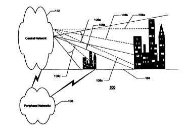
Figure lA is a block diagram of a communication system 100
suitable for implementing an embodiment. The communication system 100 can
be thought of as a hierarchic system with a set of interconnected networks,
where
each network is a node in the communication system 100, and where each
I S network is interconnected. For example, the communication system 100 can
include as nodes one or more central networks 102, user networks 104, and/or
peripheral networks 105.
Data is exchanged among the networks. In one embodiment of the
invention, data is sent from the central networks 102 to the user networks 104
using shaped and diverging coherent light beams (or light cones) 106, and data
is
sent from the user networks 104 to the central networks 102 using collimated
light beams 10$. Each individual network also can include a hierarchy of
interrelated subsystems with lower level nodes (or network elements), which is
described more fully below. Data is exchanged among the networks point-to-
point, point-to-multipoint, multipoint-to-point, or multipoint-to-multipoint,
and
point-to-multipoint communication can be broadcast, multicast, or simulcast.
For example, during point-to-point communication, any one of the
central networks 102 or their lower level nodes can transmit data from itself
to
any one node in the user networks 104 or the peripheral networks 105.
Likewise,
CA 02337763 2001-O1-12
WO 00/04660 PCT/US99/15973
6
any of the central networks 102 or their lower level nodes can receive data
from
any one of the user networks 104 or their lower level nodes, as well as from
any
one of the peripheral networks 105 or their lower level nodes.
During point-to-multipoint communication, any one of the central
networks 102 or their lower level nodes can transmit data from itself to
several
user networks 104 or their lower level nodes substantially simultaneously. Any
one of the central networks 102 or their lower level nodes can transmit data
from
itself to several peripheral networks 105 or their lower level nodes
substantially
simultaneously. Likewise, any of the central networks 102 or their lower level
nodes can receive data from any of the user networks 104 or their lower level
nodes substantially simultaneously, as well as from any of the peripheral
networks 105 or their lower level nodes substantially simultaneously.
The hierarchy of the communicatian system 100 can feature
networks interconnected with each other, as Figure lA illustrates. The
embodiment does not require that the peripheral networks 105 and the user
networks 104 be interconnected, or that the central networks 102 be connected
to
both the peripheral networks 105 and the user networks 104. Moreover, the
central networks 102 may be interconnected to each other such that data is
transmitted among the individual central networks 102 without passing through
a
peripheral network 105 or a user network 104. This particular embodiment
reduces the costs of operation, for example, by allowing central networks to
carry
their own backbone traffic, unlike other wireless networks that dedicate all
of
their bandwidth to the user networks.
In one embodiment of the invention, a user network 104 is operated
by a user that subscribes with the peripheral networks 105 and/or the central
networks 102 to send and receive data in a client-server environment. The
users
may be located at a manufacturing facility, a multinational corporation. a
financial institution, or a university, for example, with buildings that house
the
network components. In that instance, the central networks 102, the user
networks 104, and the peripheral networks 105 connect "client" systems with
CA 02337763 2001-O1-12
WO 00/04660 PCT/US99/15973
7
"server'' systems so that the server systems may perform a computation,
retrieve
a file, or search a database for a particular entry in response to a request
by the
client system. A particular type of client-server environment is not essential
to
the embodiment. It will be apparent to those skilled in the art that the
embodiments may be implemented in other client-server environments, such as
airline flight reservations systems, mail-order facilities, etc.
The peripheral networks 105 can be any interconnected network
operated by a common carrier, including a Public Switched Telephone Network
(PSTN), a Local Exchange Carrier (LEC) network providing local
telecommunication services, an Interexchange Carrier (IXC) providing long
distance telecommunication services, a satellite network, a value added
network
(e.g., providing dial-up stock market quoting services, electronic mail
services,
etc.). Alternatively, the peripheral networks 105 can be a collection of
networks
functioning as a virtual network, including the Internet, the World Wide Web,
etc. The peripheral networks 105 also can include data communication networks
such as Local Area Networks (LANs), Metropolitan Area Networks (MANS), or
Wide Area Networks (WANs). Of course, those skilled in the art will appreciate
that a particular type of peripheral network 105 is not required by the
embodiment. Instead, any type of peripheral network 105 may be used.
In one embodiment, the central networks 102, the user networks
104, and the peripheral networks 105 utilize Synchronous Optical Network
(SONET) technology, which is an optical interface standard that allows
internetworking of transmission products from multiple vendors. That is, when
the communication system 100 implements SONET technology, interconnection
of the networks enables worldwide data communication. Moreover, when the
communication system 100 implements SONET technology, a new digital
hierarchy ideally suited to handling fiber-based signals and at the same time
allowing easy extraction of lower rate signals is accomplished. These include
unified operations and maintenance and the flexibility to allow for future
service
offerings.
CA 02337763 2001-O1-12
WO 00/04660 PCTNS99/15973
8
In an alternative embodiment, the central networks 102, the user
networks 104, and the peripheral networks 105 utilize Gigabit Ethernet
technology, which is an optical interface standard that allows internetworking
of
transmission products from multiple vendors. That is, when the communication
system 100 implements Gigabit Ethernet technology, interconnection of the
networks enables worldwide data communication, especially real-time voice and
video and high-end server support. Moreover, when the communication system
100 implements Gigabit Ethernet technology, a new digital hierarchy ideally
suited to handling fiber-based signals and at the same time allowing easy
extraction of lower rate signals is accomplished. These include unified
operations and maintenance and the flexibility to allow for future service
offerings.
Figure 1B is an isometric view showing a side of the
communication system 100, where data is exchanged between the central
networks 102 and the user networks 104 in free space using the light cones
106a-c and the collimated light beams 108a-c. In one embodiment, the light
cones 106a-c are shaped and diverging coherent light beams, such as light
amplification of stimulated emission of radiation, or ''laser"' beams. Laser
beams
are directional, and can operate in a range of wavelengths in the "light"
region of
the electromagnetic spectrum, including visible light, near-infrared light,
and
infrared light. When the light cones 106a-c are laser beams, the light cones
106a-c accommodate high bit rate, high power, high coupling efficiency, direct
high frequency modulation, and long haul operations. In one embodiment, the
light cones 106a-c are eye-safe, class one laser beams, in accordance with
American National Standards Institute (ANSI) standards. In alternative
embodiments, the light cones 106a-c operate in accordance with other ANSI
standards.
The use of particular wavelengths of laser light provides high
bandwidth with very little attenuation (or power loss) in the atmosphere.
Moreover, using laser light allows interconnection with SONET architectures
CA 02337763 2001-O1-12
WO 00/04660 PCT/US99115973
9
operating at high speeds between central networks 102 typical of off the-shelf
data transmission equipment currently available. Moreover, in this embodiment,
using the SONET protocol allows arbitrary bandwidth allocation in the well-
known portions of T-1 capacity. That is, when the communication system 100
uses the laser lights with SONET, it can accommodate a digital transmission
link
with the capacity of 1.544 Mbps to many different users across remote
distances.
One embodiment of the communication system 100 uses an
infrared laser with a wavelength of approximately 1550nm. Of course, those
skilled in the art will appreciate that a particular wavelength in the light
region of
the electromagnetic spectrum is not required by the embodiment. Instead, any
wavelength in the light region may be used.
The light cones 106a-c and the collimated light beams 108a-c can
be generated using any well-known holographic optical elements that shape,
filter, and diverge or collimate the light appropriately. For example, beam
shaping can be accomplished using diffraction gratings, lenses, holographic
optical elements, or other standard beam-shaping optic. Wavelength filtering,
used in various channelization schemes, can also be achieved using a variety
of
standard optical components such as interference filters, diffraction
gratings, or
prisms.
As is described more fully below, the light cones 106a-c bit rate in
one embodiment may be between 10 Mbps and 10 Gbps, inclusive. Of course,
those skilled in the relevant art will appreciate that a particular data rate
is not
required for the embodiment. That is, the embodiments of the invention support
any number of data rates.
As is the case with the light cones 106a-c, the collimated light
beams 108a-c also can be laser beams or any light beam at a wavelength in the
"light" region of the electromagnetic spectrum, including visible light, near-
infrared light, and infrared Light. Collimating can be accomplished in a well-
known manner, such as by using a diffraction gratings, lenses, or other
standard
beam-shaping optics.
CA 02337763 2001-O1-12
WO 00/04660 PCT/US99/15973
Of course, those skilled in the art will appreciate that, while much
of the communications within the communication system 100 involves the
wireless exchange of extremely high-speed. broadcast, digital data. the
communication network 100 also supports conventional methods of data
5 communication, such as telephone lines. For example. a central network 102
can
transmit Internet video data at an extremely high speed to a user network 104
using a light cone 106a, with the return communication from the user network
104 to the central network 102 being via a standard telephone line. This may
be
the case when the Internet data is graphics and text. and the user data is
credit
10 card information, for example. This also may be the case when the Internet
data
is graphics and text, and the user data is user authorization information, for
example.
Moreover, those skilled in the art will appreciate that, while the
communication system 100 can involve the wireless exchange of extremely high
speed, broadcast, digital data, the communication system 100 can use other
data
rates. That is, the communication system 100 can communicate at data rates
commensurate with the type service being provided, the quality of service
requested, type of information transmitted and/or received, etc.
Downlink Transmission and Reception Structure
Figure 2 is a block diagram of illustrative central network 102
downlink transmission components. In this embodiment, the peripheral networks
105 send data for transmission to the user networks 104 via a central
router/switcher 204, a central downlink signal processor 206, and a central
transmit antenna 208. A central system controller 210 controls the operation
of
the central router/switcher 204 and the central downlink signal processor 206.
Generally, data travels along the thick interconnection lines, while other
commands, control signals. etc., travel along the thin interconnection lines.
Data
and other commands, control signals, etc., may also travel on thin and thick
interconnection lines, respectively.
CA 02337763 2001-O1-12
WO 00/04660 PCT/US99/159~3
11
For purposes of explanation, only one central network 102 is
described with respect to certain aspects of the embodiment of Figure 2. It is
to
be understood that the embodiment contemplates one or more central networks
102.
The central router/switcher 204 connects the central network 102 to
the peripheral networks 105 and to the user networks 104, enabling data to be
exchanged between them. The central router/switcher 204 can interconnect
network interface controllers (NICs), disk controllers, graphic display
adapters,
etc., to the central network 102. For example, the central router/switcher 204
supports NICs implemented in a G-NIC Network Interface Card available from
Packet Engines of Spokane, Washington, adapted from 830nm to l S~Onm.
Other illustrative central router/switcher 204 implementations
include well-known 10/100 Mbps Ethernet NICs with 64-bit Peripheral
Component Interconnect (PCI) buses, which support either Windows NTTM or
the Digital LJNIX~~ operating system. When the peripheral network 105 is the
Internet, the central router/switcher 204 can support Internet points of
presence
(POPS).
The central router/switcher 204 in one embodiment is a fiber optic
backbone that interconnects lower level network elements in the peripheral
networks 105 or the central networks 102. In that embodiment, and where the
communication system 100 is a packet-switched network, the central
router/switcher 204 is the main path for data packets. Packet-switched
networks
are described more fully below.
The central router/switcher 204 also interconnects the components
that transmit the light cones 106 and receive the collimated light beams 108.
The
central router/switcher 204 manages the routing of data through the
communication system 100. For example the central router/switcher 204 divides
the central network 102 into logical software-oriented sub-networks, enabling
data traffic to be more efficiently routed. The central router/switcher 204
also
performs load balancing, partitioning, and statistical analysis on data
traffic. The
CA 02337763 2001-O1-12
WO 00/04660 PCT/US99/15973
12
central router/switcher 204 also determines routing priorities, and performs
troubleshooting tasks. The central router/switcher 204 also selects the paths
that
data from the light beam 108 or data to the light cone 106 will take in the
communication system 100. The central router/switcher 204 may dynamically
route data based on the quality of service required or the amount of data
traffic in
the central network 102.
In one embodiment, the central router/switcher 204 implements a
link state routing algorithm that calculates routes based on the number of
routers,
transmission speed, delays, and route costs. This embodiment can be
implemented using an "open shortest path first'' (OSPF) protocol running on a
PowerRail 5200 Gigabit Ethernet routing switch available from Packet Engines.
The central router/switcher 204 also includes several queues that hold data
waiting to be routed.
The central downlink signal processor 206 receives the data to be
I S sent to the user networks 104 from the central router/switcher 204 and
encodes,
modulates, encrypts, buffers, and amplifies the data to produce a carrier
whose
frequency is in the visible or near-infrared region of the electromagnetic
spectrum. A carrier with such a high frequency is sometimes referred to herein
as an ''optical signal," an "optical carrier." a "carrier," a "carrier
signal." a
"lightwave signal,'' a "light cone," or a ''light beam."
The central downlink signal processor 206 also shapes the carrier
signal for transmission by the central transmit antenna 208. The structure and
operation of the central downlink signal processor 206 is described in greater
detail below with reference to Figure 4, including queuing of data waiting to
be
processed.
The central transmit antenna 208 transmits the carrier into free
space. For purposes of explanation, only one central transmit antenna 208 is
described with respect to the illustrated embodiment of the invention. It is
to be
understood that the embodiment can contemplate one or more central transmit
CA 02337763 2001-O1-12
WO 00/04660 PCT/US99/15973
13
antennas per local central network and one or more central networks per
geographic location.
According to an embodiment, the central transmit antenna 208
transmits the carrier into free space using geometric optics. such as
refractive,
reflective, diffractive, or holographic optics. Imaging geometric optics
(IGOs)
have the capability of making an image of an object. The image may either be a
"real image'' or a "virtual image.'' A real image is one that is cast on a
screen, for
example. A virtual image is viewed through an eyepiece.
To accomplish this task, an IGO has two properties: ( I ) Parallel
light rays passing through the optics are focused to a single point (the
"focus'');
and (2) Light rays incident from different angles are focused to different
foci, all
of which lie in a plane (the "focal plane"). A telescope, camera lens, shade
projector, magnifying lenses, and contact lenses are examples of imaging
geometric optics.
Non-imaging geometric optics (NGOs) do not satisfy at least one of
the criterion necessary for an IGO. If one tries to observe an image created
by
NGOs, the image will either be ''fuzzy" or nonexistent. Examples of NGOs are
the Fresnel lenses used in front of motor vehicle headlights or the rippled
"privacy" glass used in certain windows where privacy is required.
A diffraction grating is an example of an NGO suitable for
implementing one embodiment of the invention. Of course, any diffraction
grating suitable for focusing the desired wavelength that can focus the light
cone
106 into a small enough spot could be used. In this embodiment, a diameter for
the light cone 106 is 60 microns. Those skilled in the art will appreciate
that the
particular diameter is dependent upon the desired data rate.
Although IGOs are adequate, they are expensive and the
embodiment does not require all of their capabilities. Thus, one embodiment
uses NGOs to maximize the utility of the system while minimizing the cost of
the
transmit and receive optics. A suitable non-imaging geometric optic operating
in
the 1550nm range is available from Richardson Labs in Meridian, Idaho.
CA 02337763 2001-O1-12
WO 40/04660 PCT/US99/15973
14
The central system controller 210 controls the operation of the
central router/switcher 204, and the central downlink signal processor 206.
The
central system controller 210 can be implemented in hardware, software. or a
combination of both hardware and software. In aspects that are implemented
using software, the software may be stored on a computer program product (such
as an optical disk, a magnetic disk, a floppy disk, etc.) or a program storage
device (such as an optical disk drive, a magnetic disk drive, a floppy disk
drive,
etc.). The central system controller 210 may also be custom software running
on
a composite of computers (or processors).
Figure 2A illustrates a flow diagram of a central system controller
210 transmit function 200 suitable for implementing the custom software
running
on a composite of computers. Operation of the transmit function 200 begins
with
step 211, where control immediately passes to step 212. In step 212, the
transmit
function 200 determines which of its data queues advances next to send data to
the central downlink signal processor 206. In step 214, the transmit function
200
synchronizes encoding and multiplexing schemes. In an embodiment, a user
system controller 310 (see, e.g., Figure 3) synchronizes encoding and
multiplexing schemes with the user networks 104. That is, the central system
controller 210 performs handshaking with the user networks 104 to initiate a
data
transfer.
In step 216, the transmit function 200 determines the particular
encoding required. Typically, the user networks 104 control the encryption
scheme. while the central networks 102 control the multiplexing and encoding
schemes. Thus, in an embodiment, the central controller 210 determines the
particular encoding required.
In step 218, the transmit function 200 decides when a data packet is
to be transmitted. In an embodiment, the central system controller 310 makes
this decision. Operation of the transmit function 200 is complete following
step
218, as indicated by step 220.
CA 02337763 2001-O1-12
WO 00/04660 PCT/US99/15973
The output of the central networks 102 on the downlink are the
light cones 106. which are transmitted into free space and received by the
user
networks 104. That is, each of the central networks 102 transmits data
modulated on a shaped and diverging coherent or other light beam through free
5 space.
Figure 3 is a block diagram of illustrative user network 104
downlink reception components. A user antenna 302 receives data transmitted
from the central network 102, processes it using a user downlink signal
processor
304, and sends the data to user equipment and devices 308, the user system
10 controller 310. and/or any of the peripheral networks 105. For purposes of
explanation, only one user network 104 may be described with respect to
certain
aspects of the embodiment shown in Figure 3. It is to be understood that
embodiments of the invention contemplate one or more user networks I04.
As mentioned above, the user antenna 302 receives the light cones
15 106 from free space. The user antenna 302 receives the light cones 106
using an
optical receiving antenna, which, in one embodiment, uses holographic optical
elements. One embodiment uses well-known telescopes to receive the light
cones 106. For example, the user antenna 302 can be a reflective telescope
with
a modified eyepiece to further confine the spot size of the received light.
The
user antenna 302 outputs the received light cones 106 to the user downlink
signal
processor 304.
The user downlink signal processor 304 receives the light cone 106
and decodes, demodulates, decrypts, and buffers it to separate the data from
the
carrier. The structure and operation of the user downlink signal processor 304
is
described in greater detail below with reference to Figure S.
The user input/output interface 306 interconnects the user
equipment 308, the user system controller 310, and the peripheral networks
105.
Recall that in one embodiment, the user network 104 is operated by a user that
subscribes to send and receive data in a client-server environment, such that
the
central networks 102, the user networks 104, and the peripheral networks 105
CA 02337763 2001-O1-12
WO 00/04660 PCT/US99/15973
16
connect "client" systems with "server'' systems. The user input/output
interface
306 interconnects the client systems with the server systems using appropriate
signaling and protocols. In one aspect, the user input/output interface 306
supports well-known full-duplex operation and flow control common to client-
s server environments. In another aspect, the user input/output interface 306
supports Signaling Network Management Protocol (SNMP), which is a well-
known method by which network management applications query a management
agent using a supported Management Information Base (MIB). This
embodiment manages virtually any network type, to include Non-Transmission
Control Protocol (non-TCP) devices, such as IEEE 802.1 Ethernet bridges.
The user inputloutput interface 306 supports bidirectional
encryption, with the ability to change keys as needed. The user input/output
interface 306 also implements ''challenge'' and "reply'' authentication when
setting the keys. In this embodiment, the user input/output interface 306 has
a
1 ~ unique serial number, even though it does not have a unique network
address,
which serial number can be used for encryption and other security features.
The
firmware on the subscriber input/output interface 306 also is protected from
hacking.
The user equipment and devices 308 can be any of a variety of
well-known equipment, such as gateways, local area networks, bridges. etc. The
user equipment and devices 308 also can be any of a number of well-known user
devices, such as printers, hard drives, graphical display adapters,
televisions
(TVs), TV set top boxes, telecommunication equipment, video conferencing
equipment, and audiovisual equipment. such as home theater electronics, etc.
The user system controller 310 operation and structure are similar
to the operation and structure of the central system controller 210, in that
the user
system controller 310 controls the operation of the user downlink signal
processor 304 and the user input/output interface 306. The user system
controller
310 likewise can be implemented in hardware, software, or a combination of
both
hardware and software. In embodiments that are implemented using software,
CA 02337763 2001-O1-12
WO 00/04660 PCT/US99/15973
17
the software may be stored on a computer program product (such as an optical
disk, a magnetic disk, a floppy disk, etc.) or a program storage device (such
as an
optical disk drive, a magnetic disk drive, a floppy disk drive, etc.).
The user system controller 310 may also be custom software
running on a composite of computers (or processors). In one embodiment, trie
user system controller 310 is implemented in a token ring time-division
multiplex
(TDM) system.
Figure 3A illustrates a flow diagram of a data transmit routine 300
suitable for use with the user system controller 310 in this embodiment. The
transmit routine 300 begins with step 311, where control immediately passes to
step 312 wherein the transmit routine 300 determines the type, amount. and
rate
of data to be transmitted.
In step 314, the transmit routine 300 communicates the information
gathered in step 312 to the central system controller 210. In step 316, the
transmit routine 300 transmits data during the life of the token. In step 317,
the
transmit routine 300 determines if no more data exist, and in step 318 returns
a
token to the central system controller 210. If in step 318, no more data
returns a
token to the central system controller 210, the transmit routine 300 returns
to step
312.
In step 320, if there is more data, the transmit routine 300 waits for
the next token from the central system controller 210, and then the transmit
routine 300 returns to step 312.
Figure 3B is a receive routine 350 that the user system controller
310 implements in the token ring TDM system embodiment. For example, in
.step 352, the receive routine 350 receives a data packet and demodulates it.
In
step 354, the receive routine 350 examines the data packet header, and
determines if the data packet address matches a user system address.
In step 356, the receive routine 350 determines whether the address
of the data packet matches the user's system address. If the address is a
match,
then control of the receive routine 350 passes to step 358, wherein the
receive
CA 02337763 2001-O1-12
WO 00/04660 PCT/US99/15973
18
routine 350 decrypts the data packet. In step 360, the receive routine 350
sends
the data packet to the user's sub-network.
If; on the other hand, in step 356 it is determined that the data
packet address does not match a user system address, operation of the receive
routine 350 passes to step 362, wherein the receive routine 350 dumps the data
packet.
Figure 4 is a block diagram of illustrative central downlink signal
processor 206 components. The illustrative central downlink signal processor
206 includes encoders 402, modulators 404, multiplexers 406. and power
amplifiers 408 that convert data into a carrier, and amplify the carrier for
transmission in free space to the user networks 104.
The encoders 402 convert data into a representation of the data
according to a set of rules or conventions specifying the way in which the
signals
representing the data can be formed, transmitted.. received, and processed. In
one
aspect, the encoders 402 encodes data and control signals into a high-speed
data
stream. Illustrative encoders 402 are implemented in a Media Access Controller
(MAC) chip on Packet Engines' G-NIC. Of course, the encoders 402 can be
implemented in any Ethernet card, switch, or repeater with the same encoding
capabilities.
The modulators 404 modulate the light cone 106 according to the
data to be transmitted on that light cone 106. There are several types of well-
known modulation schemes used for communications (e.g., frequency
modulation. phase modulation, phase-shift keying modulation. quadrature
amplitude modulation, etc.), any of which are suitable for implementing
communication in the communication system 100. In one embodiment, the
modulators 404 are implemented in well-known Ethernet Peripheral Component
Interface (PCI) cards whose input and output are via optical fiber. In this
embodiment. the modulators 404 use a well-known on-off keying (OOK)
amplitude modulation scheme. The OOK amplitude modulation scheme is the
lowest cost modulation scheme currently available. Of course, the modulators
CA 02337763 2001-O1-12
WO 00/04660 PCT/US99/15973
19
404 can be implemented in any Ethernet card, switch, or repeater with the same
modulating capabilities. An embodiment uses the serializing/deserializing chip
on Packet Engines' G-NIC to implement the modulation task. as well as to drive
the laser.
The multiplexers 406 in one aspect are wavelength division
multiplexers (WDMs) that establish optical channels by combining the
wavelengths (or colors) into the light cone 106. That is, the multiplexers 406
mix
several channels at different wavelengths and output the wavelengths on the
same light beam. In this aspect, the multiplexers 40b can be well-known
passive
combiners or selective combiners. In another aspect, the multiplexers 406 are
optical time division multiplexers (OTDM), or high density wavelength division
multiplexers (HDWDM). Alternatively, multiplexers 406 can be implemented
using coherent multi-channel heterodyne or homodyne detection techniques. In
fact, any type of optical combiner that can perform the function of combining
the
channels, such as fused filter couplers or Soliton multiplexers, also can be
used to
implement the multiplexers 406. Of course, the invention is not limited by the
particular type of multiplexing. For example, the channels can be combined
into
the light cone 106 using frequency, polarization, spatial position, polarity,
space,
algebraic transform methods, etc. An embodiment of the multiplexers 406 uses a
dense wavelength division multiplexer (DWDM) to select channels at
International Telecommunications Union (ITU) standards for the 1530nm-
1560nm range (approximately 0.8nm separation between channels).
The power amplifiers 408 may receive and amplify one or more
wavelengths that will be present in the light cone 106. The power amplifiers
408
tolerate optical signals of many formats (or modulation schemes, such as
polarity
shift keying or amplitude shift keying) or bit rate (up to many Gbps), e.g.,
the
power amplifiers 408 are transparent. In one embodiment of the invention. one
geographic locality contains three central network stations. The signals from
each of these central network stations are divided into 36 sectors. Each
sector is
capable of carrying up to eight channels at 100 Mbps to 10 Gbps each. with an
CA 02337763 2001-O1-12
WO 00/04660 PCT/US99/15973
overall local geographic capacity of up to 8.650 terabits per second (Tbps)
(e.g.,
3 stations x 36 sectors x 8 channels x 10 Gbps.) In an embodiment, the power
amplifiers are erbium doped fiber optic amplifiers (EDFA), that amplify one or
more wavelengths simultaneously, available from JDS Fitel Corporation in
Nepean, Ontario, Canada.
Figure ~ is a block diagram of illustrative user downlink signal
processor 304 components. The embodiment user downlink signal processor 304
includes light cone detectors 502, user demodulators 504, user demultiplexers
506, and user decoders 508. which detect and separate data from the carrier in
the
10 light cone 106 after it is received from free space by the user antenna
302.
The light cone detectors 502 detect and focus the light cone 106
onto a photodetector (not shown). The light cone detectors 502 may include a
concentrator (not shown) which concentrates the light cone 106 and focuses it
without loss. After detecting and focusing, the data on the Light cone 106 is
1 ~ amplified with a preamplifier (not shown), converted to serial form with a
serializes (not shown), and protocol converted using a protocol converter (not
shown). The preamplifier, serializes, and protocol converter are available in
a
G-NIC network interface card manufactured by Packet Engines, as described
above with reference to the modulators 404. In this embodiment, the protocol
20 converter can either convert the modulation of the light cone 106 to a
Gigabit
Ethernet format or reduce it down to a 100 Mbit format. The detectors also
include well-known pattern masks, such as diffraction gratings. The light cone
detectors 502 output the light cone 106 to the user demodulators 504.
Illustrative
light cone detectors 502 are implemented in PIN diode in an off the-shelf
1550nm transceiver unit manufactured by MRV Communications located at
20415 Nordhoff Street. Chatsworth, California 91311.
The user demodulators 504 demodulate the carrier using well-
known demodulation techniques compatible with the modulation schemes used
by the modulators 404. For example, in one embodiment, the user demodulators
504 are implemented in the Ethernet PCI cards.
CA 02337763 2001-O1-12
WO 00/04660 PCT/US99/15973
21
The user demultiplexers 506 separate the wavelengths back into
frequency-separated independent optical channels using techniques compatible
with the multiplexers 406. The demultiplexers 506 can be well-known passive
splitters or selective splitters.
S The user decoders 508 convert data from the representation of the
data established by the encoders 402. For example, the user decoders 508
decodes data and control signals from a high-speed data stream. An embodiment
is implemented in a MAC chip on Packet Engines' G-NIC. Of course, the user
decoders 508 can be implemented in any Ethernet card, switch. or repeater with
the same encoding capabilities. The user decoders 508 output decoded data to
the user input/output interface 306, which then makes the data available to
the
peripheral networks 105.
Any or all of the components in the embodiments in Figures 2 and
4 or Figures 3 and 5 can be implemented on a single card, respectively. In one
1 ~ embodiment of the invention, the components in Figures 2 and 4 are
implemented in a single card from Packet Engines. Similarly, the components in
Figures 3 and 5 are implemented in a single card from Packet Engines. Of
course, those skilled in the relevant art will appreciate that a particular
physical
location for the components in Figures 2 and 4 or Figures 3 and 5.
respectively, is
not essential to practice the embodiment.
Downlink Transmission and Reception Operation
Figure 6 is a flow diagram of a downlink data transmission and
reception process 600 performed by the central network 102 downlink
transmission components, the user network 104 downlink reception components.
and the peripheral networks 105. The process 600 starts at step 602, where
control immediately passes to step 604. In step 604, the central
router/switcher
204 receives data from the peripheral networks 105 designated for recipients
in
the user networks 104 or other central networks 102.
CA 02337763 2001-O1-12
WO 00/04660 PCT/US99/15973
22
In step 606, the central router/switcher 204 routes the data to the
central downlink signal processor 206, where in step 608, the data is
processed
for transmission using the encoders 402, modulators 404, multiplexers 406, and
power amplifiers 408. Following encoding, modulation, multiplexing, and
amplifying, in step 610, the central transmit antenna 208 transmits the data
into
free space on the light cone 106.
In step 612, the user antenna 302 receives the light cone 106. The
user downlink signal processor 304 processes the light cone 106 to remove the
data from the carrier, and to separate out one or more of the channels. In
step
614, the user input/output interface 306 sends that data to the peripheral
networks
105, as indicated by step 616 and/or to the user equipment and devices 308,
indicated by step 618, as appropriate. Following steps 616 and 618, operation
of
the process 600 is complete. as indicated by step 620.
Uplink Transmission and Reception Structure
Figure 7 is a block diagram of illustrative user network 104 uplink
transmission components. The peripheral network 105 sends data for
transmission to the central networks 102 via the user input/output interface
306
and/or the user equipment and devices 308 and sends it to a user uplink signal
processor 702. The user uplink signal processor 702 outputs the data to the
user
antenna 302 for transmission into free space on the collimated light beam 108.
which is received by the central networks 102. The user uplink signal
processor
702 is described more fully below with reference to Figure 9.
Figure 8 is a block diagram of illustrative central networks 102
uplink reception components. A central receive antenna tiUZ recemes data
transmitted from the user networks 104, processes the data using a central
uplink
signal processor 804, and routes the data to the peripheral networks 105 via
the
central router/switcher 204. The central system controller 210 controls the
operation of the central router/switcher 204 and the central uplink signal
CA 02337763 2001-O1-12
WO 00/04660 PCT/US99/15973
23
processor 804. The central uplink signal processor 804 is described more fully
below with reference to Figure 10.
Figure 9 is a block diagram of illustrative user uplink signal
processor 702 components. The illustrative user uplink signal processor 702
includes user multiplexers 902, user modulators 904, and user optical
transmitters
906. The multiplexers 902 operate similarly to the multiplexers 406 in the
central downlink signal processor 206, in that the multiplexers 902 can
combine
channels using WDM, OTDM, HDWDM, coherent mufti-channel heterodyne or
homodyne detection techniques. fused filter couplers, or Soliton multiplexers.
for
example.
The user modulators 904 operate similarly to the modulators 404 of
the central downlink signal processor 206. For example, the user modulators
904
can implement several types of well-known modulation schemes used for
communications. In one aspect of the invention, the user modulators 904 are
I S implemented in well-known Ethernet PCI cards whose input and output are
via
optical fiber. The user optical transmitters 906 perform well-known optical
signal processing on the data prior to output to the user antenna 302. An
illustrative optical transmitter 906 includes a laser, an amplifier, and a
telescope.
This embodiment uses a telescope manufactured by Meade in Irvine, California.
whose eyepiece has been adapted to allow a fiber optic element to be inserted
into the eyepiece (so that the laser light can be sent into the telescope, and
thus,
transmitted into free space).
The output of the user optical transmitters 906 is sent to the user
antenna 302, which transmits the multiplexed and modulated data as the
collimated light beam 108 to the central networks 102. The central networks
102
receive the collimated light beam 108, process it using the central uplink
signal
processor 804. and send the data to any of the peripheral networks 105.
Figure 10 is a block diagram of illustrative central network 102
uplink components. As Figure 10 shows, the central receive antenna 802
receives the collimated light beams 108 from free space. The central receive
CA 02337763 2001-O1-12
WO 00/04660 PCT/US99/15973
24
antenna 802 receives the collimated light beams 108 using an optical receiving
antenna, which, in one embodiment of the invention, uses holographic optical
elements.
The central uplink signal processor 804 includes collimated beam
detectors 1002. central demodulators 1004, and central demultiplexers 1006.
The
collimated beam detectors 1002 detect and focus the collimated light beam 108
and provide spatial offsets to spatially separate and separately detect each
collimated light beam 108 whether on identical or differing wavelengths. The
collimated beam detectors 1002 can be similar to a two-dimensional array of
photodetectors, each receiving a collimated light beam 108 from a different
user
network 104 or a lower level node. The collimated beam detectors 1002 output
signals corresponding to the different collimated light beams 108. The central
receive antenna 802 outputs the signals corresponding to the different
received
collimated light beams 108 to the central demodulators 1004. In one
1 S embodiment, the collimated beam detectors 1002 focus the collimated light
beam
108 onto a 1500nm detector that detects data at rates in excess of 10 Mbps.
Such
detector is available from MRV Communications.
The central demodulators 1004 demodulate the carrier using well-
known demodulation techniques compatible with the modulation schemes used
by the user modulators 904. For example, in one embodiment. the user
demodulators 1004 are implemented in well-known Ethernet PCI cards.
The central demultiplexers 1006 further separate the wavelengths
back into spatially independent optical channels using techniques compatible
with the user multiplexers 902. As such, the central demultiplexers 1006 can
be
well-known passive splitters or selective splitters. The central
demultiplexers
1006 output data to the central router/switcher 204, which then makes the data
available to the peripheral networks 105.
CA 02337763 2001-O1-12
WO 00/04660 PCT/US99/15973
Uplink Transmission and Reception Operation
Figure 11 is a flow diagram of an uplink data transmission
reception process 1100 performed by the central network 102 uplink
transmission
components, the user network 104 uplink reception components, and the
5 peripheral networks 105. The process 1100 starts at step 1102, where control
immediately passes to step 1104. In step 1104, the user input/output interface
306 receives data from the peripheral networks 105 and routes the data to the
user uplink signal processor 702.
In step 1106. the user uplink signal processor 702 processes the
10 data for transmission using the user multiplexers 902. user modulators 904,
and
user optical transmitters 906. In step 1108, the user antenna 302 transmits
the
data into free space on the collimated light beam 108 into free space. In step
I110, the central receive antenna 802 receives the collimated light beam 108
from free space.
15 In step 1112. the central uplink signal processor 804 invokes steps
352 through 358 of the user system controller 310 receive function 350 (see,
e.g.,
Figure 3B) and processes the collimated light beam 108 to remove the data from
the carrier, and to separate out one or more of the channels.
In step 1114, the central router/switcher 204 sends that data to the
20 peripheral networks 105, as indicated by step 1114 and/or to other central
networks 102, indicated by step 1116, as appropriate. Following steps lII4 and
1116, operation of the process 1100 is complete, as indicated by step 1118.
It is noted that it can be less expensive to transmit from the user
networks 104 to the central network 102 using the collimated light beam 108 as
25 opposed to a shaped and diverging light cone 106, as is transmitted from
the
central network 102 to the user networks 104. For example, the collimated
light
beams 108 require less power. Moreover, transmitting using the collimated
light
beams 108 ensures that there is little interference between bidirectional
light
transmissions between the central networks 102 and the user networks 104.
CA 02337763 2001-O1-12
WO 00/04660 PCT/US99/15973
26
Recall that the communication system 100 (see, e.g., Figure 1 ) also
supports conventional methods of data communication. Accordingly, the
communication network 100 can communicate at data rates commensurate with
the medium of communication. For example, the communication system 100 can
transmit into free space at one data rate and receive via telephone lines at a
different (e.g., lower) data rate.
Data Packet Structure
As described above, the communication system 100 uses packet-
switching technology, in which data is divided into individual data packets
before
transmission and routed through different network elements and may therefore
arrive at different times or out of sequence. If received out of sequence, the
individual data packets are reassembled at the intended destination.
i=figure 12 illustrates a data packet 1200 suitable for use with the
communication system 100. The data packet 1200 includes a payload 1202,
1 S which typically is the data content. For example, the data content can be
stock
quotes, video/audio for a teleconference, etc. Those skilled in the art will
appreciate that the particular payload may vary according to the application
and
may include information needed to facilitate reassembly of the data packets
into
the original data sequence.
The data packet 1200 also includes a header 1204. The header
1204 typically includes a destination address 1206 that specifies the
destination
network element (or recipient) to which the data packet 1200 is to be routed.
That is. the address 1206 specifies which central network 102, user network
104,
or peripheral network 105, or their lower level nodes is the designated
recipient
of the particular data packet 1200. When the recipients recognize their
particular
address 1206 in the data packet 1200, the recipients accept the payload 1202
appended to the address 1206.
The data packet 1200 also includes a cyclical redundancy check
(CRC) 1208, that is used to detect errors in the transmission of the data
packet
CA 02337763 2001-O1-12
WO 00/04660 PCT/US99/15973
27
1200. Other forms of error detection and correction may be used in place of.
or
in addition to. the CRC 1208. The data packet 1200 may also include error
correction data under any conventional error correction method. The data
packet
1200 also includes a miscellaneous portion 1210 for miscellaneous control or
data information, such as for multicasting or broadcasting sessions. An
illustrative data packet 1200 is a SONET data packet structure. An alternative
is
a standard Internet Protocol (IP) data packet, (e.g., IPv.4 (IPv.6) data
packets
with IEEE Ethernet 802.3 framing).
Sectorization
Recall that in one embodiment, data is sent from the central
networks 102 to the user networks 104 using the light cones 106, and that the
light cones 106 are shaped and diverging coherent light beams. Several shaped
and diverging coherent light cones 106 are radiated in the substantially
circular
radiation pattern that illuminates any or all parts of the area surrounding
the
central networks 102, much like a theatrical spotlight illuminates a stage.
Parts
of the illuminated areas can be emphasized, or made "brighter" than others, in
order to deliver more signal strength to chosen areas. As is the case with the
theatrical spotlight. the light cones 106 can be configured into any shape.
The
radiation pattern radii can be anywhere from one quarter meter to over three
kilometers.
Each central network 102 optically shapes the laser radiation
patterns into the narrow radial sectors containing elevation sectors into
which the
wavelengths of infrared laser lights are transmitted. In one embodiment. the
central downlink signal processor 206 shapes the laser beam into the desired
radiation pattern, with radial (or horizontal) sectors and/or elevation (or
vertical)
sectors further divided into several channels. Each channel is allocated
particular
wavelengths. A user can be assigned a wavelength such that the central
networks
102 transmit a high-speed data stream to each user or group of users on the
assigned wavelength. Each vertical sector and each horizontal sector may have
CA 02337763 2001-O1-12
WO 00/04660 PCT/US99/iS973
28
one or more channels of different wavelengths. Each of the channels may carry
at least 10 Gbps of data. This arrangement accommodates a data transmitting
capacity in excess of 20 Tbps and can service thousands of users.
Figure 13 illustrates an illustrative transmission point 1301 with
sectorization 1300. According to this embodiment, there are several horizontal
subsectors, as represented by subsectors 1302a, 1302b and 1302c. Each sector
may have vertical subsectors, as represented by subsectors 1306a and 1306b.
Each vertical or horizontal subsector may be further divided into another
subsector. Each horizontal subsector 1302a-c and/or vertical subsector 1306a-c
can have one or more wavelength channels (not shown).
When the communication system 100 communicates using the
transmission point 1301 with the sectorization pattern 1300, the address in
the
data packet 1200 specifies the appropriate sector 1302 and wavelength channel.
It should be noted that the highly controllable shaped beams make
wavelength (or frequency) reuse a non-issue using the communication system
100. The sectors in the communication system 100 are strictly spatially
separated, and so any channel can be used in any sector. This spatial reuse
technique provides distinct advantages over common non-optical systems.
Conventional frequency reuse schemes were necessary because of radiation
pattern side lobe interference caused by well-known right phrasing.
Implementation of sectorization and shaped and diverging coherent light beams
106 avoids side lobe interference problems and, thus, avoids the need for
frequency-reuse schemes. To accomplish this, the central transmit antennas 208
use central geometric antennas that are very large in terms of operating
wavelength (e.g., approximately eighty times the wavelength). Conversely,
conventional radio antennas are approximately the same size as the carrier
wavelength, so they cannot use geometric optics for their transmission
sectors.
The transmission point 1301 with the sectorization pattern 1300
can generate several types of "footprints,'' as defined herein as an area of
coverage projected onto the buildings housing the user networks 104 by the
beam
CA 02337763 2001-O1-12
WO 00/04660 PCT/US99/15973
29
radiated from the transmission point 1301. In an embodiment. the transmission
point 1301 has shaped sectorization designed to project a roughly circular
footprint on the buildings housing the user networks 104.
Of course, the invention is not limited by the shape of the
footprints. Figure 14 illustrates examples of various suitable footprints
1402a-f
generated by the central transmit antennas 208. While, in some cases. only one
central transmit antenna 208 is illustrated per set of light cones 106
transmitted, it
is to be understood that, for example. the central transmit antenna 208a
includes
several telescopes, each capable of generating a uniquely shaped radiation
pattern. For example, as one telescope of the central transmit antenna 208c
generates a light cone 106d which produces a substantially circular footprint
1402d, another telescope of the central transmit antenna 208c generates a
light
cone (not shown) which produces a substantially heptagonal footprints 1402c.
Other footprints include elliptical, hexagonal, donut-shaped,
square, etc. For example, referring back to Figure 13, the subsector 1302a
would
generate an elliptical footprint. The subsector 1306a produces a hexagonal
footprint. The subsector 1306b generates a donut-shaped footprint.
One purpose for overlapping radiation patterns is to deliver data at
different data rates or capacities to the same building. Of course. the
particular
radiation pattern used is determined by a number of factors, including the
size
and shape of the building that houses the user networks, for example, that
ensure
that the power in the optical signal is effectively utilized.
The communication system 100 also can include an optical repeater
1404, which receives, reconstructs, and amplifies either one way or
bidirectionally the light cones 106 and retransmits them to the user networks
104.
The optical repeater 1404 compensates for dead spots in the transmitting
radiation patterns. The optical repeater 1404 thus acts as an extension
between
central networks 102. The optical repeater 1404, while depicted as a single
element, may contain multiple receiver-transmitter pairs that detect,
reconstruct,
CA 02337763 2001-O1-12
WO 00/04660 PCT/US99/15973
amplify. and retransmit the light cones 106 under the components discussed
above with respect to Figures 2-6.
Figure 15 shows an illustrative topography 1500 surrounding the
central networks 102, by the sectorization pattern 1300. The embodiment
depicted in the topography 1500 includes three hexagonal light propagation
patterns 1502a, 1502b, and 1502c. In this embodiment. each sectorization
pattern 1300 has 36 sectors, where one sector in each sectorization pattern
1300
is represented by the sectors 1502a,, 1502b,, and 1502c,, respectively. An
alternative embodiment has 60 radial sectors, each with six degrees of
azimuth.
10 and five elevation sectors, each with eight channels accommodating a data
rate
from 10 Mbps to 10 Gbps. Still another embodiment divides a radiation pattern
into 120 three-degree sectors, with each sector delivering 10 Mbps to 10 Gbps
to
the user networks 104.
Figure 15 also depicts several central networks 102 interconnected
1 ~ by ultra-wide bandwidth optical backbone links 1510. The optical backbone
links 1510 also allow interconnection with Internet POPs, major carriers, the
PSTN, or other peripheral networks 105.
The systems, methods, and interconnected devices for networked,
high-speed bi-directional data communication through free space described
20 herein are particularly suitable for use in foggy weather conditions, where
optical
signals are susceptible to attenuation. A study in London, England of point-to-
point laser communication produced data on reliability that, when combined
with
a historical database, produced a weather database with forty years of data
collected on an hourly basis. With this kind of information, the parameters of
the
25 communication system 100 can be modified to compensate for certain
atmospheric conditions. For example, the power output of the central transmit
antennas 208 and/or the user antennas 302, radii of the cells, sensitivity of
the
detectors and/or the data rate can be increased or decreased as appropriate.
Similarly, the size of the antennas can be adjusted to compensate for any
30 anticipated attenuation of the signal.
CA 02337763 2001-O1-12
WO 00/04660 PCT/US99/15973
31
The coverage area of the radiation pattern generated by the central
transmit antenna 208 also can be predetermined by design to anticipate
atmospheric conditions. For example, in the city of Seattle, Washington which
is
known for foggy conditions typically causing strong attenuation. the radiation
S patterns can be reduced to one quarter kilometer, as opposed to the two
kilometer
radiation patterns appropriate for sunny locations.
Other suitable modifications include changing the shape of the light
cones 106. changing the tint of the windows through which the light
beams/light
cones are transmitted, changing the optical amplifier strengths. etc.
Broadcast and Multicast Operation
Recall that the communication system 100 broadcasts and
multicasts data from the central networks 102. During broadcast operations.
the
data is transmitted from any one of the central networks 102 or their lower
level
nodes to all user networks 104 and/or all peripheral networks 105 and/or their
lower level nodes. for example. Any well-known broadcast addressing scheme is
suitable for implementing this embodiment.
During point-to-muitipoint multicast communication, selected user
networks 104. peripheral networks 105, and/or their lower level nodes receive
data. This embodiment is ideal in situations where identical data content is
desired to be transmitted to a particular group of user networks 104 and/or
peripheral networks 105 substantially simultaneously (e.g., during video
teleconferences).
In this embodiment, the miscellaneous portion 1210 of the data
packet 1200, depicted in Figure 12, includes a multicast session identifier
(not
shown) that identifies a multicast session and a set of users that are the
recipients
of the transmission during the particular multicast session. The content of
the
transmission that one member of a multicast session group receives is
substantially the same as the high-speed data that another member of the
multicast session group receives during a particular multicast session.
CA 02337763 2001-O1-12
WO 00/04660 PCT/US99/15973
32
Each multicast session identifier is associated with a set of unique
addresses. There is a unique address for each recipient of the multicasted
data.
The central network 102 transmits the multicast session identifiers to the
recipients, which use the association to determine the unique address for each
of
the recipients associated with the set of unique addresses. The central
network
102 adds the unique addresses for the recipients to each data packet 1200
received from the other interconnected networks prior to transmitting the
received data packet 1200 to the specified set of recipients.
Each central network 102 also may include a plurality of multicast
session identifier translation tables to translate multicast session
identifiers into
unique addresses for the subscribers. There may be one or more multicast
sessions identified by multicast session identifiers. Each of the multicast
session
identifiers is associated with a set of unique addresses representing a set of
users.
The central network 102 includes at least one translation table to correlate
the
multisession identifiers with each set of unique addresses for the set of
selected
recipients.
Table 1 is an example of a multicast session identifier table suitable
for use with one embodiment of the invention. Table 1 lists example multicast
sessions ( 1 through 4), functional group identifiers (A through D) for the
functional groups associated with a particular multicast session, sets of
addresses
for the particular recipients in the particular functional group, and
recipients
associated with the unique addresses designated to receive transmissions
during
the particular multicast session. Note that the multicast sessions may have
overlapping recipients such that one recipient may be included in the
multicast
session '' 1" as well as in the multicast session ''2." Note that the
recipients are
designated 104a through 104d to represent either several user networks 104 or
several of their lower level nodes.
CA 02337763 2001-O1-12
WO 00/04660 PCT/US99/15973
33
Table 1
Multicast Functional Unique AddressesRecipients
Session Group ID
1 A 0112.3456.7890 104a
0223.4567.8901 1046
0334.5678.9012 104c
0445.6789.0123 104d
2 B 0445.6789.0123 104d
0223.4567.8901 1046
0334.5678.9012 104c
3 C 0445.6789.0123 104d
O 112.3456.7890104a
4 D 0445.6789.0123 104d
0334.5678.9012 104c
Figure 16 is a flowchart showing an illustrative multicast process
1600. The multicast process 1600 starts at step 1602, where control
immediately
passes to step 1604. In step 1604, one of the peripheral networks 105
transmits
high-speed data and a multicast session identifier to the central network 102.
For
example, according to Table 1, during the first multicast session: one of the
peripheral networks 105 transmits the functional group identifier "A'' to the
central network 102.
In step 1606, the central network 102 receives the high-speed data
and the multicast session identifier. In step 1608, the central network 102
determines the functional group associated with the multicast session by
looking
in its translation table. In step 1610, the central network 102 determines the
set
of recipients in the functional group.
I S In step 1612, the central network 102 determines the unique
address of each recipient in the set of recipients in the functional group.
For
example, the central network 102 looks in its multicast session identifier
translation table to determine the unique address for the sets of recipients
associated with the functional group identifier "A.'' In step 1614, the
central
network 102 adds the unique address for the sets of recipients to the high-
speed
data received from the central network 102 and transmits the resulting high-
speed
data to the recipients 104a-d. Once the high-speed data has been transmitted
CA 02337763 2001-O1-12
WO 00/04660 PCT/US99/15973
34
from the central network 102 to the recipients 104a-d, the multicast process
1600
ends, as indicated by step 1616.
It is noted that the multiplexing and demultiplexing schemes used
by the central networks 102 differ from the multiplexing and demultiplexing
S schemes used by the user networks 104 in that the central networks' 102
multiplexing and demultiplexing schemes have additional levels of address
translation to accommodate routing of incoming IP addresses to the appropriate
addressees. The additional routing is implemented in the central
router/switcher
204.
All of the optics described herein can be enclosed in a "black box."
such as a Faraday cage, to isolate the optical components from outside
interference such as extraneous optical frequencies. Enclosing the optics in a
black box is less expensive and simpler than conventional methods for
eliminating outside interference.
1 S Recall that the central router/switcher 204 connects the central
network 102 to the peripheral networks lOS and to the user networks 104,
enabling data to be exchanged between them. Recall further that the central
router/switcher 204 supports NICs implemented in a G-NIC Network Interface
Card available from Packet Engines. Figure 17 shows an illustrative central
router/switcher 204 implemented on the G-NIC Network Interface Card.
The central router/switcher 204 in this embodiment includes a
gigabit uplink port 1702 and up to two server ports: an optional gigabit
server
port 1704 and a 10/ 100 Ethernet server port 1706. The central router/switcher
204 also includes a glue logic and memory control processor 1707. The gigabit
uplink port 1702 receives data packets 1200 on its input and sends the data
packets 1200 to the output of whichever server port is active. At the same
time.
the central router/switcher 204 sends any data packets 1200 received on an
input
of the active server port to the output of the gigabit up link port 1702.
It is noted that all data packets 1200 coming from either server port
1704, 1706 will be sent to the gigabit uplink port 1702, but the data packets
1200
CA 02337763 2001-O1-12
WO 00/04660 PCT/US99/15973
coming from the gigabit uplink port 1702 destined for either server port 1704,
1706 will be filtered by the glue logic and memory control processor 1707.
That
is, only the data packets 1200 meeting the filter requirements will be sent to
the
appropriate server port 1704. 1706. At a minimum. the gigabit uplink port 1702
5 filters received data packets 1200 by accepting only the data packets 1200
destined for a particular Ethernet address. In this embodiment, the gigabit
uplink
port 1702 also accept broadcast data packets and multicast data packets. In
one
embodiment, filtering may be performed by a host computer system under the
purview of a user network 104.
10 The central router/switcher 204 in another embodiment is
connected from one of the server ports directly to a matching port on a host
computer system located at a user network 104. In this embodiment, if the
gigabit uplink port 1702 uses the same Ethernet address as the pori on the
host
computer system, the central router/switcher 204 supports only that host on
its
15 gigabit uplink port 1702. This is because the Ethernet address of the host
computer system is programmed into the central router/switcher 204.
In another embodiment, the central router/switcher 204 "auto-
discovers'' its Ethernet address from the data packets 1200 seen on the server
ports. Alternatively, central router/switcher 204 is preprogrammed with the
same
20 Ethernet address as an Ethernet card assigned to the host computer system.
Some Additional Features
The communication system 100 increases bath the transmit and
receive communication capacity of conventional communication systems. The
greater capacity is important to note because standard telephone lines are
being
25 pushed to their limit and can provide only approximately 60 Kbps of data
network connection. Other network alternatives have been developed but have
their limitations as well. For example, ISDN, once thought to be the wide area
networking solution of choice, is limited to 128 Kbps. The newly touted ADSL
services are limited to eight Mbps and are asymmetric (fast in only one
CA 02337763 2001-O1-12
WO 00/04660 PCTNS99/15973
36
direction-the downlink). Existing personal computers (PCs) have the ability to
network locally at over 100 Mbps, leaving these wide area network technologies
extremely inadequate.
The most publicized attempt to break the bandwidth bottleneck
incorporates satellites in low-Earth orbits (LEO). These satellite networks
can
obtain data down-link rates from 1.5-28 Mbps. The cost to deploy these
systems,
however, ranges into billions of dollars and requires years to deploy.
Fiber optic and LMDS art also available and planned technologies
in the telecommunication market. While LMDS is thought to require only 25
percent of the capital cost of deploying optical fiber, there appears to be an
upper
limit from four to six Gbps of total traffic capacity per four kilometer wide
cell,
which places a significant limit on system growth. For example. in an area
rivice
the size of downtown Seattle's business core, only 40 to 60 concurrent
customers
could have 100 Mbps access. In contrast, the optical communication system 100
1 S can potentially serve up to thousands of such concurrent connections.
The communication system 100 may only require 30 percent of the
capital cost of an LMDS (or approximately eight percent of fiber) without the
two Gbps limitation of total capacity per cell. Recall that the communication
system 100 has the ability to communicate at 2.5 Gbps duplex or 1.2~ simplex
per channel, and its overall capacity per system may be in excess of two Tbps.
This capacity is 1,000 times higher than LMDS and translates to significantly
lower infrastructure costs, and the ability to undercut competitors' pricing
and/or
outperform competitive offerings.
The communication system 100 accomplishes these staggering
speeds/volumes by combining wireless, fiber, and networking concepts to form a
unique network that has the ability to deliver terabits of information around
the
world in a very timely and cost-efficient manner.
The communication system 100 antennas are similar in size and
shape to a small dish antenna of the type that can be found on many rooftops.
CA 02337763 2001-O1-12
WO 00/04660 PCT/US99/15973
37
However, the antennas may be placed behind a window glass, making
deployment much easier than rooftop-only installations.
While the technology that the communication system 100
implements allows for a radiation pattern radii well over three kilometers.
for
urban cores, however, the central networks 102 can be much smaller and
dependent upon the geography of the region as well as the building size and
building location. Moreover, as described above, the communication system 100
has a very advantageous channel re-use property, allowing significantly lower
costs. significantly higher capacities, and greater bandwidth.
Using a very simple example, assume one central network 102 is
sectored into 120 three-degree sectors, with each sector delivering 100 Mbps
to
2.5 Gbps. In this very simple example, this single central network 102 has the
ability to deliver 300 Gbps to a large number of users. With the addition of
additional channels per sector, the data throughput increases signiftcancly.
By
using eight channels per sector, the optical communication system 100 has the
ability to effectively increase the data throughput on a single local central
network 102 to 2.4 Tbps. Such a central network 102 could supply 100 Mbps
service to 24,000 concurrent users. This far exceeds conventional
communication systems. The only close competitor is LMDS, which currently is
limited to about four Gbps per cell site.
Many of the components in the communication system 100 may be
implemented using hardware, software, or a combination of hardware and
software, and may be implemented in a computer system or other processing
system. In aspects where the invention is implemented using hardware. the
hardware components may be Application-Specific Integrated Circuits (ASICs),
or a hardware state machine. In aspects that are implemented using software,
the
software may be stored on a computer program product (such as an optical disk.
a magnetic disk, a floppy disk, etc.) or a program storage device (such as an
optical disk drive, a magnetic disk drive, a floppy disk drive, etc.). That
is.
software may be available from a removable disk or from code downloaded on a
CA 02337763 2001-O1-12
WO 00/04660 PCT/US99/159~3
38
hard drive. Moreover, the software can include code stored in a module such as
a
Read-Only Memory (ROM), Programmable ROM (PROM), or any variation of
an Erasable PROM (e.g., EPROM, EEPROM, etc.).
According to one embodiment, the communication system 100 uses
well-known Time Division Multiple Access {TDMA) techniques. In TDMA,
each user network 104 is assigned one or more TDMA time slots based on the
allocated wavelength (or data rate), and the networks communicate with each
other during the designated TDMA time slots. When the communication system
100 uses TDMA technology, the communication system 100 can multiplex
several user networks 104 on one TDMA channel, using a well-known
diffraction grading (or pattern mask) to receive only certain bits from the
data
stream for each user network 104.
A resource manager (not shown) coordinates assignments of
TDMA time slots. The resource manager negotiates for a channel (e.g., a time
slot at a particular frequency).
Interconnection of the arrangement of the light cones 106 and the
collimated light beams 108 may be done using standard Internet protocols, such
as "open shortest path first' (OSPF), which is a link state routing algorithm
that
is used to calculate routes based on the number of routers, transmission
speed,
delays, and route costs. Interconnection of the light cones 106 and the
collimated
light beams 108 can also be accomplished using other well-known routing
algorithms.
Figure 18 shows an alternative embodiment of the communication
system 100. This alternative embodiment uses a mufti-access
receiver/transmitter (MART) 1802 for both transmission and reception: The
central network 102 is connected to the MART 1802 by a transmission link 1800.
The transmission link 1800 is a hardwire link, such as a telephone line or
fiber
optic cable, but it is also possible to use a wireless link (e.g., radio
frequency,
laser light, ete.). Additionally, while Figure 18 depicts the central network
102
CA 02337763 2001-O1-12
WO 00/04660 PCT/US99/15973
39
and the MART 1802 as being separated, remote components. it is appreciated
that the MART 1802 can be within the central network 102.
The MART 1802 includes an array 1804 of central transmit
antennas 208 and central receive antennas 802. The central transmit antennas
208 in Figure 18 are coaxially located at the center of their respective
central
receive antennas 802. Other modifications are possible. For instance, the
central
transmit antennas 208 may be located near (e.g , separated from) their
respective
central receive antennas 802, instead of being coaxially located. It is also
possible to use the same optical device to transmit and receive if wavelength
separation between the transmitted and received signals is adequate.
Downlink transmission from the central network 102 to the user
network 104 and/or the peripheral network 105 uses a concept of splitting a
single broadcast beam into several light cones 106, with each light cone 106
having all of the information present in the single broadcast beam. First, one
or
more power amplifiers 408, such as a 500 mW EDFA, in the MART 1802 splits
the single broadcast beam received through the transmission link 1800 and
provides the individual signals to respective central transmit antennas 208.
The
central transmit antennas 208 then transmit the individual signals as light
cones
106 to the user network 104 and/or the peripheral network 105. The array 1804,
or the individual central transmit antennas 208 and central receive antennas
802,
can be mounted, for example, onto one or more gimbal structures to direct the
transmitted light cones 106. Available optics are used to focus and direct the
light cones 106 as necessary.
The embodiment shown in Figure 18 allows one or more light
cones 106 to be focused on particular receivers in the user network 104 or the
peripheral network 105. That is, instead of transmitting to an entire
building,
separate light cones 106 can be transmitted to particular receivers in the
building.
Further, the separate light cones 106 can have different power, such that
light
cones 106 having greater power are transmitted to receivers that are farther
away
or are behind darkly tinted windows, and light cones 106 having less power are
CA 02337763 2001-O1-12
WO 00!04660 PCT/US99/15973
transmitted to closer-range receivers. Also, the MART 1802 can transmit to
more than one building, such that some light cones 106 are transmitted to one
building and other light cones 106 are transmitted to other buildings. By
adjusting the power level of the transmission and pointing the central
transmit
antennas 208 in the appropriate direction, it is thus possible to ''link"
several
buildings and at greater distances from the same MART 1802. To maximize
efficiency, a given power output of the power amplifier 408 can be apportioned
between the various light cones 106, such that light cones 106 requiring less
power are reduced in power while the other light cones 106 requiring more
10 power are correspondingly increased in power.
Further, the scope of transmission coverage of the MART 1802 is
easily changed by adjusting the number of splits in the power amplifier 408. A
sector of up to a full hemisphere is possible by splitting a single broadcast
signal
with the power amplifier 408 and providing central transmit antennas 208 in
each
15 quadrant.
The MART 1802 can also receive collimated light beams 108 from
the user network 104 and/or peripheral network 105. A plurality of collimated
light beams 108 transmitted from individual transmitters in the user network
104
and/or the peripheral network 105 are received by the central receive antennas
20 802 in the MART 1802. Like the transmission from the MART 1802 described
above, the uplink transmission of collimated light beams 108 from the user
network 104 and/or the peripheral network 105 to the MART 1802 allows
multiple signals to be linked at the MART 1802.
Many possible design parameters can be used for the embodiment
25 shown in Figure 18. For instance, a 12° sector can project a light
cone 106 of
100 meters in diameter at a distance of 500 meters. A three mrad beam can
project a light cone 106 having a diameter of 1.5 meters at a distance of S00
meters. Using the same transmit power and assuming zero losses during the
split. a three mrad beam can be projected at each of 4.444 customers and have
the
30 same power density as the 12° sector. Alternatively, service can be
provided to
CA 02337763 2001-O1-12
WO 00/04660 PCT/US99/15973
41
100 customers, with a 16 dB of link margin for each. The increased link margin
can be used to reduce the size and costs of each customer's receiver.
Although specific aspects of; and examples for the invention are
described herein for illustrative purposes, various equivalent modifications
are
possible within the scope of the invention and can be made without deviating
from the spirit and scope of the invention, as will be recognized by those
skilled
in the relevant art. For instance, although a laser has been described herein
as
generating the various light beams and light transmissions, other light-
generating
devices, such as light-emitting diodes (LEDs), can be used. Also, although the
collimated light beams 108 are used in the network uplink components (see.
e.g.,
Figures 7-10) and the light cones 106 are used in the network downlink
components (see, e.g., Figures 2 and 3-5) in the embodiments described herein,
it
is to be appreciated that in some embodiments, the network uplink components
can use the light cones 106 or the network downlink components can use the
collimated light beams 108. Further, several channels (e.g., frequency
.domain)
can be used in the uplink as well, with appropriate coordination between a
user
and a central node.
The teachings provided herein of embodiments of the invention can
be applied to optical links made functional by any standard net<vork
interconnection. For example. the G-NIC Network Interface Card (see. e.g.,
Figure 2) can be implemented in PCs. Further, one or more components or
functions of the communication system 100 can be embodied in a computer
network, computer-readable media (such as magnetic cassettes, digital video
disks, CD-ROMs, Bernoulli cartridges, random access memories (RAM), ROMs,
smart cards, etc.) and their associated devices. One or more components or
functions of the communication system 100 can be embodied in computer-
readable or computer-executable instructions such as program modules or macros
executable by a microprocessor or by a computer. How to implement these types
of features can be understood by one skilled in the art based on the detailed
description provided herein.
CA 02337763 2001-O1-12
WO 00/04660 PCT/US99/15973
42
These and other changes can be made to the invention in light of
the above-detailed description. In general, in the following claims, the terms
used should not be construed to limit the invention to the specific aspects
disclosed in the specification and claims, but should be construed to include
all
optical communication systems that operate under the claims to provide, inter
alia, high-speed optical data communication. Accordingly, the invention is not
limited by the disclosure, but instead the scope of the invention is to be
determined entirely by the following claims, which are to be construed in
accordance with established doctrines of claim interpretation.