Note: Descriptions are shown in the official language in which they were submitted.
CA 02337839 2001-O1-16
WO 00/03634 PCT/US99/15196
1
Title: THERMOMETRIC APPARATUS AND METHOD
BACKGROUND OF THE INVENTION
Technical Field
This invention relates generally to the field of thermometric diagnostic
devices and
methods, and more particularly, to an apparatus and method for sensing,
recording, and
indicating thermal irregularities across a dermal surface.
History of Related Art
Foot problems are the major cause of amputation and physical disability in
patients
1 o with diabetes. Yet studies have shown that simple techniques such as
identifying patients at
risk for foot ulcers and educating these patients about proper foot care can
help prevent such
serious complications.
Preventing diabetic foot problems requires careful monitoring of the patient's
feet on
a regular basis. Unfortunately, the daily inspection of the plantar and dorsal
surfaces of the
feet require some manual dexterity and experience, and some patients may be
hampered in
their ability to conduct regular inspections because of obesity, arthritis, or
poor eyesight.
Often, mirrors or teaching a friend or family member to conduct the inspection
are required.
In addition, a necessary component in the causal pathway to foot complications
in
persons with diabetes is peripheral sensory neuropathy. Damage to sensory
feedback
2 0 concerning position and tactile stimulation of the foot provides an
environment where skin,
ligaments, or bones of the foot can be injured without any knowledge by the
patient that such
injury has occurred. For instance, areas of high pressure on the sole of the
foot normally
become irritated and inflamed because of normal walking activities. Persons
with normal pain
sensation will stop or modify their activities to avoid pain and subsequent
ulceration, or other
2 5 damage. However, in diabetics with nerve damage the sensation of pain is
often absent, and
activities are often continued until the injury is so prominent that
amputation is required.
Degenerative arthritis, bunion deformities, or hammer toes, as well as other
foot
deformities, increase the risk of developing an ulcer on the foot. Such
physical alterations in
the structure of the foot can produce high pressure areas, which in turn
produce inflammation,
3 0 tissue destruction, and ulceration. Once again, without the early warning
signal provided by
normal pain sensation, tissue damage may become quite advanced before reaching
a level
noticed by the patient. Unfortunately, by the time that such knowledge occurs,
amputation
CA 02337839 2001-O1-16
WO 00/03634 PCT/US99/15196
2
may be required.
Prevention and treatment of ulceration can be quite effective in preventing
lower
extremity amputation in diabetics. Prevention strategies focus on protecting
the sole of the
foot from high pressure areas, and detection of early signs of tissue injury.
Objective methods
of implementing these strategies, which often involve measurement of
inflammation and foot
pressures, have historically been expensive, bulky, or relatively unavailable
to physicians and
their patients. However, it has been found that an increase in local skin
temperature is one of
the earliest indications of tissue injury or inflammation. Therefore,
monitoring the skin
temperature on a monthly basis by physicians and more important, on a daily
basis by
l0 patients, can provide an easy, inexpensive, and readily quantifiable way to
detect areas of the
foot that are at risk of ulceration.
The most common method of evaluation and diagnosis for foot temperature
involves
manual manipulation of the feet with a single hand to find a warm area or "hot
spot." The
high temperature area is compared with the rest of the foot, and the
corresponding bilateral
location on the other foot. A temperature difference of more than 2°C
is clinically significant,
and is held to be detectable by the average practitioner. However, physicians
and others with
temperature-insensitive hands, or circulation problems of their own may not be
able to reliably
detect such small changes in temperature.
Various instruments have been devised to detect skin temperature, but these
are often
2 0 expensive, or formed for use in the ear, or for general use, and do not
lend themselves to use
with the faot. The display may not be visible to the user if applied to the
sole of the foot; there
is also no sure way to determine sensor proximity to the foot, or provide any
type of scanning
function which can be monitored by the user as areas of lower or higher
temperature are
encountered. Finally, such devices are ordinarily constructed so as to measure
the temperature
2 5 of any surface encountered; whether the temperature measurement is
relevant to skin, or to
some other surface within the field of view of the sensor, is not detected by
the instrument.
Therefore, what is needed is an apparatus and method for easily,
inexpensively, and
repeatedly detecting temperature differences along the sole of the foot of
about 2°C or greater.
Further, such a device and method should lend themselves to continuous
scanning of the
3 0 surface of the sole, along with reliable determination of the presence of
an anatomical surface
in front of the sensing element. Such a device and method which provide both
visual and
CA 02337839 2001-O1-16
WO 00/03634 PCT/US99/15196
3
audio indications or alarms to the practitioner and/or patient would also be
desirable for
persons hampered by poor vision or poor hearing.
SUMMARY OF THE INVENTION
In accordance with one aspect of the present invention a thermometric
apparatus has:
a controller; a timer electrically connected to the controller; a memory
electrically connected
to the controller; a means for sensing a plurality of temperatures, the
temperature sensing
means being electrically connected to the controller, the temperature sensing
means acting to
convert a plurality of temperatures to a corresponding plurality of electrical
signals, the
controller converting the plurality of electrical signals to a corresponding
plurality of
temperature numeric values, said numeric values being stored in the memory; a
contact
sensing means for sensing proximity to a dermal surface, the contact sensing
means being
electrically connected to the controller; a speaker electrically connected to
the controller; and
a display electrically connected to the controller. The controller and the
timer may be
integrated into a single unit, and the controller and memory may be integrated
into a single
unit. In addition, the contact sensing means of the thermometric apparatus of
the present
invention may comprise a switch activated by capacitance. The temperature
sensing means
of the thermometric apparatus of the present invention may comprise an
infrared sensor which
is inactive until the contact sensing means senses a predetermined capacitance
of greater than
about 10 pF. The display of the thermometric apparatus of the present
invention may
2 0 comprise a series of LEDs arranged in a linear sequence, selected ones of
the LEDs are colored
red, yellow, and green.
The plurality of numeric temperature values may be stored into the memory
within
a predetermined time period (less than about 0.08 seconds) measured by the
timer. After the
plurality of temperature numeric values are stored into the memory and
averaged by the
2 5 controller to produce a first average temperature value, the resulting
first average temperature
value is stored in the memory. A second plurality of temperature numeric
values may be
stored into the memory and averaged by the controller to produce a second
average
temperature value, which is compared with the first average temperature value.
The second
average temperature value may then be displayed on the display if the
difference between the
3 0 second average temperature value and the first average temperature value
is less than a
predetermined difference of about 0.2 °C. The second average
temperature value is typically
CA 02337839 2001-O1-16
WO 00/03634 PCT/US99/15196
4
not displayed on the display if the difference between the second average
temperature value
and the first average temperature value is greater than a predetermined
difference of about
0.2 °C.
The temperature sensing means of the thermometric apparatus of the present
invention
may be electrically connected to the controller using a signal conditioner. If
the plurality of
electrical signals comprise unwanted frequency signals, then the signal
conditioner operates
to filter the plurality of electrical signals by removing the unwanted
frequency signals. The
plurality of electrical signals may also comprise erratic values. If so, the
signal conditioner
may operate to smooth the plurality of electrical signals by removing the
erratic values. Also,
1 o the plurality of electrical signals may comprise noise, and the signal
conditioner may operate
to remove the noise.
Moreover, the temperature sensing means of the thermometric apparatus of the
present
invention may provide a type k thermocouple output to the signal conditioner.
The
temperature sensing means and the contact sensing means may be integrated into
a single
sensor head which is attached to a goose-neck.
Furthermore, the plurality of temperature numeric values stored into the
memory and
averaged by the controller to produce a first average temperature value may be
directly
displayed on the display. Additionally, a second plurality of temperature
numeric values
stored into the memory and averaged by the controller may be used to produce a
second
2 0 average temperature value. The difference between the first average
temperature value and
the second average temperature value may then be displayed on the display. The
speaker may
be used to produce an audible tone whose frequency is proportional to an
average value of the
plurality of numeric values.
In accordance with another aspect of the present invention, a method of
thermometric
2 5 diagnosis comprises approaching a first bilateral dermal surface with a
contact sensing means
until a first proximity signal is detected, acquiring a first temperature
value of the first bilateral
dermal surface after the first proximity signal is detected, approaching a
second bilateral
dermal surface with the contact sensing means until a second proximity signal
is detected, the
second bilateral dermal surface having a one-to-one physical correspondence
with the first
3 0 bilateral dermal surface, acquiring a second temperature value of the
second bilateral dermal
surface after the second proximity signal is detected, subtracting the second
temperature value
CA 02337839 2001-O1-16
WO 00/03634 PCT/US99/15196
from the first temperature value to produce a temperature difference, and
displaying the
difference on a display.
These steps may be performed repeatedly. The first bilateral dermal surface
may be
selected sole of a first foot, and the second bilateral dermal surface may be
a selected sole of
5 a second foot. The method may include the step of producing an audible tone
whose
frequency is proportional to the difference.
The method of thermometric diagnosis of the present invention may further
comprise
the steps of illuminating a green colored visual element when the difference
is less than about
2°C, illuminating a yellow colored visual element when the difference
is equal to about 2°C,
and illuminating a red colored visual element when the difference is greater
than about 2°C.
In accord with another aspect of the present invention, a method of
thermometric
diagnosis may further comprise the steps of approaching a first dermal surface
with a contact
sensing means until a first proximity signal is detected, acquiring a first
temperature value of
a first dermal surface after the first proximity signal is detected,
displaying a first temperature
value on a display; approaching a second dermal surface with the contact
sensing means until
a second proximity signal is detected; acquiring a second temperature value of
the second
dermal surface after the second proximity signal is detected, displaying a
second temperature
value on the display if the first temperature value is less than the second
temperature value;
and displaying a first temperature value on the display if the second
temperature value is less
2 0 than the first temperature value.
The method of thermometric diagnosis of the present invention may further
comprise
the steps of adding a preselected temperature value to a second temperature
value to produce
a high temperature value, subtracting a preselected temperature value from a
second
temperature value to produce a low temperature value, and emitting an audible
tone whose
2 5 frequency is proportional to subsequently acquired temperature values
which are greater than
the low temperature value and less than the high temperature value. The
preselected value
may be I.0° C.
BRIEF DESCRIPTION OF THE DRAWINGS
A more complete understanding of the structure and operation of the present
invention
3 0 may be had by reference to the following detailed description when taken
in conjunction with
the accompanying drawings, wherein:
CA 02337839 2001-O1-16
WO 00/03634 PCT/US99/15196
6
FIG. 1 is a simplified schematic block diagram of a preferred embodiment of
the
present invention;
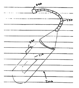
FI(i. 2 is a perspective view of one embodiment of the present invention;
FIG. 3 is a perspective view of an alternative embodiment of the present
invention;
FI(J. 4 is a plantar view of the right foot indicating isotherms; and
FI(J. 5 is a plantar view of the right and left foot, indicating bilateral
locations for
temperature measurement.
DETAILED DESCRIPTION OF PRESENTLY PREFERRED
EXEMPLARY EMBODIMENTS
Turning now to Fig. 1, a schematic block diagram of the thermometric apparatus
10
of the present invention can be seen, A controller 20, which can be similar
to, or identical to
a micromint PIC STIC 3 microcontroller, having a built-in, l2-bit differential
analog to digital
converter (ADC) is used to regulate the activity of the apparatus. Of course,
any other
commonly available microcontroller may be used. Preferred implementations
include those
controllers with built-in analog signal processing circuitry timers, memory,
and display driving
circuitry. For purposes of clarity, the timer 30 and memory 40 are illustrated
separately from
the controller 20. However, they can just as easily be combined into the
controller 20 itself.
The controller 20 typically processes analog information provided by the
temperature
sensor 50 and the contact sensor 70 after appropriate conditioning by the
signal conditioner
2 0 60. The required signal conditioning may include smoothing, filtering,
and/or noise removal,
as are well known in the signal-processing art.
The temperature sensor is identical to, or similar to, an Omega OS 36-98.6F,
which
is an infrared temperature sensor 50 having a type k thermocouple output. The
signal
conditioning required by signal conditioner 60 in this case can be provided by
a device similar
2 5 to, or identical to, an Analog Devices AD595CQ thermocouple amplifier. The
signal
conditioner 60 in this case will amplify the output of the temperature sensor
50 to provide a
signal magnitude which is compatible with the input of the ADC residing within
the controller
20.
The contact sensor 70 comprises a contact switch activated by the capacitance
of the
3 o human body in close proximity. That is, a proximal capacitance of greater
than about 1 Opf at
the switch (i.e., contact sensor 70) will cause the controller to sense the
presence of an
CA 02337839 2001-O1-16
WO 00/03634 PCT/US99/15196
7
anatomical surface, as opposed to an inanimate presence, in close proximity to
the device.
Activation of the contact sensor 70 in this fashion signals the controller 20
to begin acquisition
of temperatures via the temperature sensor 50 and signal conditioner 60. In
this particular
implementation, there is no signal conditioning required to process the signal
from the contact
sensor 70, which comprises, as mentioned above, a simple capacitance-sensitive
touch switch,
which is well known in the art. However, other approaches to detection of
anatomic proximity
may require the filtering, smoothing, and/or amplification functions of the
signal conditioner
60.
The controller 20 communicates with the user of the thermometric apparatus 10
by way
1 o of visual and audio signals. That is, any number of sounds can be
communicated to the user
by way of speaker 120. Lights 110, which can be similar to, or identical to,
LEDs, or other
visual, colored indicators, can be used as an alternative to the audio output
provided by
speaker 120. This is especially useful for those users having minimal or non-
existent hearing
capability.
A digital-to-analog converter (DAC) 80 may be used to convert digital signals
from
the controller 20 into analog signals appropriate to drive the voltmeter 90
for display of
absolute or relative temperature values, as detected by the temperature sensor
50. For more
complex implementations of the apparatus, a display 100 can be used for
indicating
temperatures, profiles, memorized values, etc. Such advance functions of the
apparatus 10
2 o will be described further hereinbelow.
Figs. 2 and 3 illustrate physical packaging concepts for the thermometric
apparatus 10
of the present invention. In Fig. 2, a FOOTSCANTM device 200 can be seen. This
particular
implementation, which is seen as relatively inexpensive embodiment of the
invention, is
intended to be used on a daily basis by an individual patient to monitor foot
temperature
2 5 fluctuations, which are indicative of foot pathology. The FOOTSCANTM
device 200 is an easy
to use, portable, hand-held device that measures the temperature anywhere on
the patient's
foot, particularly the sole. Its working range is from about 23.9° to
about 37.8°, and it has an
accuracy of about 0.3°C.
The FOOTSCANTM device 200 is intended for rapid determination by a patient of
his
3 0 or her risk of potentially catastrophic foot complications. It is a hand-
held instrument with a
goose-neck 230 flexible shaft connecting the sensor head 240, housing the
contact sensor 70
CA 02337839 2001-O1-16
WO 00/03634 PCT/US99/15196
8
and temperature sensor 50, to the hand-held case 250. A switch 220 is used to
supply power
to the device 200, while a simple display 210 is used by the patient to view
the information
resulting from application of the sensor head 240 to the foot.
The sensor head 240 is situated at the distal end of the goose-neck; it is
applied to the
sole of the foot by touching the head 240 to the foot to obtain a near
instantaneous digital
readout of the dermal temperature at the point of application. It should be
noted that the
contact sensor 70, which permits acquisition of dermal temperatures by the
temperature sensor
50, only activates when in proximity to the dermal surface. This feature
assures accurate
temperature measurements by eliminating spurious readings which may be
obtained by
l0 accidental reading of ambient conditions, or, extraneous objects which come
into the field of
view of the temperature sensor 50. Further, the ergonomic design of the
FOOTSCANTM
device 200 allows for ease of positioning on the dermal surface, even for
those patients
hampered by obesity or arthritis.
Another feature of the design includes a stabilization mechanism implemented
by the
controller 20 which makes use of multiple temperature readings at the same
location over a
short period of time (e.g. about 0.25 sec.) to obtain a stable reading. It has
been determined
that a tolerance of approximately 0.2°C between scanned readings at the
same location
provides a useful system with repeatable and accurate measurement capability.
A typical algorithm for acquiring stable temperature readings includes
repetitive
2 o acquisition of approximately ten readings, averaging the readings, and
repeating the process
three times within about 0.25 sec. If the difference between the maximum and
minimum
average values obtained is less than approximately 0.2°C, then the
average of these three
acquisition cycles can be displayed to the patient; otherwise, the process is
repeated from the
beginning. This stabilized acquisition process, or verification procedure, is
useful because it
2 5 ensures that temperature readings are only displayed after a steady state
has been reached. If
the sensor head 240 is moved too quickly across the dermal surface, the
instrument will detect
a widely varying temperature range, and accurate readings are not possible.
The verification
procedure also effectively eliminates noise in the readings.
A more advanced implementation of the apparatus of the present invention can
be seen
3 o in Fig. 3. This embodiment is referred to as the RISKSCANTM device. This
particular
embodiment is characterized by a case 310 which is designed to be small enough
for a
CA 02337839 2001-O1-16
WO 00/03634 PCT/US99/15196
9
physician to carry in his pocket. A complex display 320 is available to
present various forms
of information. However, the sensor array 330 is similar to, or identical to,
that used by the
FOOTSCANTM device 200. A non-rigid, flexible, cord 350 is used to connect the
sensor array
330 to the balance of the RISKSCANTM device electronics 300.
In addition to the simple temperature acquisition mode of the FOOTSCANTM
device
200, the RISKSCANTM device 300 can also implement an isoscan mode and a
soundscan
mode. During use, the physician will typically select the mode using the mode
switch 340 on
the front panel of the RISKSCANTM device.
In the "isoscan" mode, the RISKSCANTM device 300 is used to determine areas of
the
1 o sole which exhibit temperatures within a predetermined range of a
predefined peak
temperature. This feature allows measurement not only of the value and
location of a single
elevated temperature, but also its topographical spread along the sole. For
example, as seen
in the plantar view of the right foot in Fig. 4, the right foot 400 can be
"mapped" by areas of
first isotherm 510, second isotherm 520, third isotherm 530, and peak
temperature 540. That
is, the cooler temperatures of the foot sole typically approach a peak
temperature as shown in
the illustration. A physician will use the RISKSCANTM device 300 to fmd the
location of the
peak temperature 540, and then activate the isoscan mode, which will indicate
the
topographical spread of the peak temperature 540, by means of an audible
signal. The
"isoscan" mode is based on the concept that temperature magnitude and its
topographic
2 0 location are important indications of the diabetic foot pathophysiology.
The "isoscan" mode
allows the physician to evaluate the effectiveness of his treatment approach;
decreasing the
number or size of areas having elevated temperatures indicates that the
treatment approach is
indeed efficacious.
In the "isoscan" mode, the physician uses the RISKSCANTM device 300 to
determine
2 5 the temperature profile of the foot sole (or other skin on the body) with
respect to a peak
temperature value by scanning the entire area; the display 320 and memory 40
are constantly
updated with temperature values that are greater than any previously shown as
the sensor head
is moved aver the scanned area. That is, a first temperature value is obtained
from the scanned
area, displayed on the display 320 and stored into the memory 40. Once a
second temperature
3 o value is obtained or measured, which is greater than the first temperature
value, the second
value is displayed on the display 320 and stored into the memory 40. The first
temperature
CA 02337839 2001-O1-16
WO 00/03634 PCT/US99/15196
value is erased from the memory 40 and removed from the display 320. Once the
physician
believes that the highest value of temperature in the scanned area has been
obtained for
display, it is saved into the memory 40 as a peak temperature value. A high
temperature value
and a low temperature value are subsequently determined by adding and
subtracting,
5 respectively, one degree (or other preselected value) from the peak value
and storing the
calculated high temperature value and low temperature values into the memory
40. The
RISKSCANTM device 300 will then emit a sound with a frequency proportional to
the sensed
temperature, and no sound will be emitted whenever the currently sensed
temperature value
is higher than the high temperature value, or lower than the low temperature
value. Of course,
1 o these high and low temperature values can be set to a preselected value of
~ 1.5 degrees from
the peak value, or to a preselected value of X2.0 degrees from the peak value,
or to other
preselected values, as determined by the program in the controller 20.
The "soundscan" mode, selected by the physician using the mode switch 340,
gives
an audible tone of varying frequency which is proportional to the average
measured
temperature at the dermal surface. This feature allows the physician to gather
a mental picture
of the topagraphic temperature distribution on the sole of the foot in a very
short time period.
After using this mode, the physician can go on to the isoscan or single
temperature acquisition
modes to collect more information about sites of interest.
Other features involved in the implementation of the invention can be seen in
Fig. 5.
2 0 In this case, a plantar view of the left and right feet can be seen. The
right foot 400 has several
numbered sites which correspond to the same sites on the left foot 400'. Each
of the numbered
locations on the right foot has a corresponding "prime" location on the left
foot 400'. That is,
right upper lateral sole 410 corresponds to left upper lateral sole 410', the
right upper medial
sole 420, corresponds to the left upper medial sole 420', the right lateral
arch 430 corresponds
2 5 to left lateral arch 430', and the right heel 440 corresponds to left heel
440'.
The RISKSCANTM device 300 has the capability of remembering, or storing into
the
acquisition memory 40 of the controller 20, various temperature readings. This
makes it fairly
easy for the physician to track (or map for comparison) various suspected
locations on the sole
of the foot, typically corresponding to pressure points from the metatarsals
or other bony
3 0 prominences of the foot.
In Fig. 5, for example, the physician might decide to map locations on the
right foot
CA 02337839 2001-O1-16
WO 00/03634 PCT/US99/15196
11
400, such as the right upper lateral sole 410, the right upper medial sole
420, the right lateral
arch 430, and the right heel 440. These values will be displayed in
conjunction with the
corresponding locations on the left foot 400': left upper lateral sole 410',
left upper medial sole
420', left lateral arch 430', and left heel 440'. Differences of more than
2°C will be seen as
clinically significant and provide early indications to the attending
physician as to the
condition of the patient's feet. Further, the RISKSCANTM device 300 may be
programmed
to display the temperature differentials between corresponding locations, so
that a physician
may enter location pairs and observe immediately the temperature differences
between them.
In addition to the other features described, the apparatus of the invention
provides for
selective optical barriers to eliminate spurious signals produced by ambient
light to the
temperature sensor. Disposable templates for use by physicians or patients can
be used to
consistently locate suspect sites on the sole of the foot for repeatable
temperature measurement
and evaluation. Further, the physician may select a specific temperature as a
"target" or "zero"
point for reference, and use this reference for differential readings with
respect to the rest of
the foot. This particular use of the RISKSCANTM device 300 may also be
selected by way of
the mode switch 340. As an adjunct to the variable tones used to indicate
variable
temperatures at the speaker 120, lights 110 can also be used. For example, a
linear array of
green, yellow and red LEDs can be used to indicate temperatures near to the
target temperature
(i.e., green LEDs), temperatures approaching the 2°C clinical
difference (i.e., yellow LEDs),
2 0 and temperatures above the 2°C difference (i.e., red LEDs lighted).
Although the present invention is described in terms of preferred exemplary
embodiments, other uses of the invention may be obtained from a study of this
disclosure and
the drawings, along with the appended claims.