Note: Descriptions are shown in the official language in which they were submitted.
CA 02337909 2001-01-17
WO 00/74289 PCT/KR00/00552
-1-
TRANSMITTIN AND RECEIVING DEVICE AND METHOD FOR
CONTINUOUS Oi1TF.R-i.OOP POWER CONTROL WHILE IN DTX
MODE IN A CDMA MOBILE COMMUNICATION SYSTEM
BACKGROUND OF THE INVENTION
1 Field of the Invention
The present invention relates generally to a device and method for outer-
loop and closed-loop power control of a CDMA (Code Division Multiple Access)
mobile communication system in DTX (Discontinuous Transmission) mode, and
in particular, to a device and method for continuous outer-loop power control
of a
physical channel which transmits only power control bits (PCBs) without data.
2. Dnof the Related t~rt
Description
In IS-2000 standard, packet transmission is implemented in three ways:
the P 1 option using a fundamental traffic channel and a supplemental channel
(SCH), the P2 option using a fundamental traffic channel and a dedicated
control
channel (DCCH), and the P3 option using a fundamental traffic channel, a DCCH,
and an SCH. A traffic channel and a DCCH transmit control information about
packets and a signaling message and an SCH transmits packet data. The control
information and the signaling message are generated discontinuously. In the
absence of information the fundamental traffic channel transmits null traffic.
A
forward DCCH transmits only power control bits and a reverse DCCH transmits
only pilot symbols and power control bits if there is no information to be
transmitted. That is, the DCCH only transmits data when there is data to
transmit.
This is called a DTX mode.
Meanwhile, as for W-CDMA (Wideband-CDMA standard according to
the 3GPP, the Third Generation Partnership Project), the Japanese and European
IMT-2000 (International Mobile Telecommunications 2000) standard, a
conventional CDMA mobile communication system that provides voice service
mainly releases a channel once the data is completely transmitted and requests
a
channel and connects to the channel when necessary. However, the conventional
method cannot provide other high quality services like packet data service
because it involves many delay factors such as reconnection delay time.
Therefore, other services including packet data service should be provided in
a
new method. In many cases, data is intermittently transmitted during packet
data
service such as Internet access and file download. As a result, a non-
transmission
CA 02337909 2001-01-17
WO 00/74289 PCT/KR00/00552
-2-
period is interposed between packet data transmission periods. According to
the
conventional technology, a dedicated data channel is released or maintained
for
the non-transmission period. In the former case, a long time is taken to
reconnect
a channel, making it impossible to provide a corresponding service; whereas,
in
the latter case, channels which are transmitting no data, are maintained,
drastically reducing usage efficiency of the system. This problem can be
solved
by establishing a DCCH between a base station and a mobile station to transmit
and receive a control signal associated with a dedicated data channel for a
transmission period, and to be maintained when the dedicated data channel
released for a non-transmission period, so that channels can be used
efficiently
and channel reconnection occurs rapidly upon generation of transmission data.
This state is termed the control only substate.
An outer power control loop and a closed power control loop are used
together for power control in a DTX mode. The closed power control loop
controls power in power control group (PCG) units using a threshold fixed for
each frame, while the outer power control loop varies a threshold depending on
the presence or absence of frame errors and feeds the threshold to a closed-
loop
power controller. In the case of using both the outer power control loop and
the
closed power control loop while in DTX mode, a closed-loop power control is
executed using a threshold deterniined in the outer power control loop upon
generated of frames, and using the previous threshold in the absence of frames
to
transmit.
There will be given a description of the outer-loop power control and the
closed-loop power control in a DTX mode.
FIGs. 1A and 1B are block diagrams of a transmitter in a typical CDMA
mobile communication system. Insertion of PCBs in the DTX mode will be
described referring to FIGs. lA and 1B.
A control message buffer 111 is a memory for temporarily storing a
control message transmitted for communication of a control message on a DCCH.
The message buffer 111 is configured to have a capacity enough to store one or
more frames. The control message buffer 111 interfaces a control message
between a higher layer processor and a MODEM controller 113. The higher
layer processor stores a control message added with header information to
identify a frame according to a message type in the control message buffer
111,
CA 02337909 2001-01-17
WO 00/74289 PCT/KR00/00552
-3-
sets a flag to notify the storage, reads the control message from the control
message buffer 113, and clears the flag to notify the read, thereby preventing
over-write and over-read.
The MODEM controller 113 reads the control message from the control
message buffer 111, the MODEM controller 113 determines a message type by
analyzing the header of the control message, and outputs a payload to be
transmitted on a DCCH according to the message type and a corresponding
control signal. The control message is variable in duration according to the
analysis result, usually 5 or 20ms. The MODEM controller 113 determines
whether there is a control message to transmit and controls transmission of
the
DCCH. That is, the MODEM controller 113 generates a first gain control signal
Gc in the presence of a control message to be transmitted and a second gain
control signal Gc for blocking signal transmission on the DCCH in the absence
of
a control message. The gain control signals are signals for controlling the
transmission power of the DCCH. While the gain controller is located at the
front end of a spreader, the same effect can be produced even if it is at the
rear
end of the spreader.
The MODEM controller 113 controls transmission of the DCCH while in
DTX mode. That is, the MODEM controller 113 performs a DTX mode control
according to the capacities of the data service signals and MAC (medium access
control) related messages communicated on the DCCH, to thereby use channel
capacity efficiently. Since voice traffic and signal traffic are multiplexed
in IS-95,
both a voice channel and a signaling channel should be opened all the time for
data service. However, the DCCH operates in the DTX mode and thus need not
be opened for a control signal If no signaling information to be transmitted
exists,
a DTX gain controller reduces transmission power for efficient use of radio
resources.
A CRC (Cyclic Redundancy Check) generator 115 adds a CRC to the
control message received from the MODEM controller 113 to allow a receiver to
determine the quality of a frame, that is, the presence or absence of a frame
error.
The CRC generator 115 outputs a control message with the CRC under the
control of the MODEM controller 113. A 40-bit control message with a 16-bit
CRC is generated for a 5ms-frame, and a 184-bit control message with a 12-bit
CRC for a 20ms-frame.
A tail bit encoder 117 analyzes the output of the CRC generator 115 and
CA 02337909 2001-01-17
WO 00/74289 PCT/KR00/00552
-4-
adds corresponding tail bits to the output of the CRC generator 115, for
terminating an error correction code. Here, the tail bit encoder 117 generates
8
tail bits.
An encoder 119 encodes the output of the tail bit encoder 117 at a code
rate of 1/3. The encoder 119 can be a convolutional encoder or a turbo
encoder.
An interleaver 121 permutes the bit sequence of encoded symbols received from
the encoder 119 in frame units to protect the data from burst errors.
The CRC generator 115, the tail bit encoder 117, the encoder 119, and
the interleaver 121 form a control message generator 150 for generating a
control
message and transmitting it on a physical channel. While the control message
generator 150 processes a control message for a frame in FIG. 1A, it can be
contemplated that the MODEM controller 113 selects a control message
generator corresponding to the length of a frame to transmit among as many
control message generators as the frame lengths of control messages
transmitted
on the DCCH In this case, each control message generator should be provided
with a CRC generator, a tail bit encoder, an encoder, and an interleaver
according
to the frame length of a control message processed in the control message
generator.
A signal mapper 123 maps 1 s and Os of the interleaved symbols to -1 s
and ls, respectively. A gain multiplier 125 performs a DTX mode function by
establishing a path for transmitting the DCCH control message or blocking the
path depending on which gain control message is received from the MODEM
controller 113.
A PCB inserter 127 inserts a PCB into a signal received from the
multiplier 125. A serial-to-parallel converter (SPC or S/P) 129 multiplexes
control message symbols received from the PCB inserter 127 and distributes the
multiplexed symbols to carrier spreaders. Here, three carriers are used by way
of
example. For the three carriers, six channels are produced from three carrier
frequencies and two phases (I and Q channels) of each carrier. The PCB can be
used for controlling the reverse link power of a mobile station.
FIG. 1B is a block diagram of a spreader for spreading symbols received
from the PCB inserter 127. A forward link transmitter includes as many as
spreaders as carriers. One spreader corresponding to one carrier is shown in
FIG.
CA 02337909 2001-01-17
WO 00/74289 PCT/KROO/00552
-5-
lB. Referring to FIG. 1B, an orthogonal code generator 135 generates a DCCH
orthogonal code which can be a Walsh code or a quasi-orthogonal code.
Multipliers 131 and 133 multiply I- and Q-channel signals of the forward DCCH
control message by the orthogonal code, for orthogonal spreading.
A modulator 137 PN-spreads the orthogonally spread I- and Q-channel
signals received from the multipliers 131 and 133 with PN codes PNi and PNq
received from a PN sequence generator (not shown). A complex multiplier can
be used as the modulator 137.
The above embodiment is a 3x multi-carrier system and can be applied to
a transmitter in a lx or 3x DS (direct sequence) system. Thus, a description
of
the lx or 3x DS system will be omitted.
FIG. 2 is a block diagram of a reverse link transmitter which operates in a
DTX mode for the general CDMA mobile communication system. As shown in
FIG. 2, the reverse link transmitter is similar to the forward link
transmitter in
structure. Therefore, a description of the same components will be omitted.
An orthogonal spreader 207 generates a Walsh code. A first multiplier
209 multiplies a transmission signal received from a signal mapper 205 by the
Walsh code received from the orthogonal spreader 207, for orthogonal
spreading.
A gain multiplier 221 outputs no data upon receipt of a gain control signal 0
from
a MODEM controller 203 if there is no transmission message and outputs data
upon receipt of a gain control signal 1 from the MODEM controller 203 if a
transmission message exists. A summing device 223 forms a DCCH signal by
summing the transmission signal received from the gain multiplier 221 and a
pilot/PCB channel sigaal. A PN spreader 225 complex-PN-spreads the DCCH
signal
FIG. 25A is a block diagram of a base station transmitter in a typical
asynchronous IMT-2000 system. A description of the same components as in
FIG. 1 will be omitted. In FIG. 25A, a rate converter 2517 changes the rate of
the output signal of an encoder 2515 to that of the input signal of an
interleaver
2519 by repeating or puncturing the output of the encoder 2515 when the rate
at
the output of the encoder 2515 is different from that at the input of the
interleaver
2519. A multiplexer 2523 time-division-multiplexes a gain-controlled dedicated
physical data channel (DPDCH) and a dedicated physical control channel
CA 02337909 2001-01-17
WO 00/74289 PCT/KR00/00552
-6-
(DPCCH) and feeds the multiplexed signal to a signal mapper 2525.
FIG. 26A is a block diagram of a mobile station transmitter in the typical
asynchronous IMT-2000 system. As shown in FIG. 26A, the mobile station
transmitter is similar to the base station transmitter in structure.
Therefore, a
description of the configuration and operation of the mobile station
transmitter
will be omitted herein.
There will be given a description of the structures and operations of
forward and reverse link receivers for performing an outer-loop power control
and a closed-loop power control using a reverse pilot channel and a PCB
received
on a forward DCCH, respectively, with reference to FIGs. 3 and 4.
FIG. 3 is a block diagram of a reverse link receiver in a DTX mode for
the general CDMA mobile communication system.
Referring to FIG. 3, a first despreader 301 is a PN despreader for PN-
despreading a received signal. A second despreader 303 is a DCCH Walsh
despreader for despreading a DCCH signal included in the PN-despread signal
received from the first despreader 301 with a Walsh code. A channel estimator
305 detects a fading component using a pilot channel included in the PN-
despread signal received from the first despreader 301. A third despreader 307
is
a pilot channel Walsh despreader for despreading the pilot channel signal
included in the PN-despread signal received from the first despreader. 301
with a
Walsh code.
A multiplier 314 multiplies the complex conjugate of the fading
component received from the channel estimator 305 by the DCCH signal
received from the second despreader 303 in symbol units, for error
compensation.
A PCB extractor 317 extracts a PCB from the error-compensated DCCH signal
received from the multiplier 314. A bit energy measurer 309 measures bit
energy
Eb from the PCB received from the PCB extractor 317 and the fading component
received from the channel estimator 305. A noise measurer 311 measures noise
energy Nt from the symbol value of the pilot channel received from the third
despreader 307 and the fading component from the channel estimator 305. An
SNR calculator 313 calculates an SNR from the noise energy Nt and the bit
energy Eb. For details of an Eb and Nt measuring method, see "Forward Link
Closed Loop Power Control Method for cdma 2000-(Rev 1)", Stein Lundby,
CA 02337909 2001-01-17
WO 00/74289 PCT/KR00/00552
-7-
Contribution to TR45.5.3. l./98.12.08.28.
A decoder 319 decodes the output of the PCB extractor 317 and a CRC
error detector 321 performs a CRC error check on the decoded signal received
from the decoder 319. The output of the CRC error detector 321 is True (1) or
False (0). Since the DCCH channel is transmitted in the DTX mode, the receiver
calculates a CRC from a frame if the frame has transmission data to determine
whether a frame error has occurred. For details of a method of determining
whether a DCCH has frame data or not while in DTX mode, see Korea
Application No. 98-04498. A data detector 323 receives frame data and a CRC
error check result from the CRC error detector 321 and generates an on/off
control signai to a MODEM controller 325. The MODEM controller 325 is
activated by the on/off control signal to detect a control message from the
decoded data received from the decoder 319 and to store the control message in
a
control message buffer 327.
If the receiver performs closed-loop power control alone, a closed-loop
power controller 315 compares the SNR of each PCB received from the SNR
calculator 313 with a fixed threshold and controls power according to the
comparison result. If the receiver performs closed-loop power control and
outer-
loop power control together, an outer-loop power controller 329 is further
provided to the receiver. The outer-loop power controller 329 determines a
threshold and then the closed-loop power controller 315 performs a closed-loop
power control using the threshold. The outer-loop power controller 329 is
activated upon receipt of a frame existence flag from the data detector 323
and
determines the threshold from the CRC check result received from the CRC error
detector 321.
Referring to FIG. 6, a closed-loop power control method in the above
reverse link receiver will be described.
In step 601, the SNR calculator 313 calculates an SNR from Nt and Eb
measured by the noise measurer 311 and the bit energy measurer 309,
respectively. Upon receipt of the SNR from the SNR calculator 313, the closed-
loop power controller 315 compares the SNR with a fixed threshold in step 603.
If the SNR is greater than the threshold, the closed-loop power controller 315
transmits a power-down command (PCB=O) to a mobile station in step 605. If
the SNR is equal to or greater than the threshold, the closed-loop power
CA 02337909 2001-01-17
WO 00/74289 PCT/KR00/00552
-S-
controller 315 transmits a power-up command (PCB=1) to the mobile station in
step 607.
FIG. 4 is a block diagram of a forward link receiver in a DTX mode in
the general CDMA mobile communication system. The structure and operation
of the forward link receiver will be described referring to FIG. 4.
In FIG. 4, a squarer 401 squares an input signal in sub-chip units. An
accumulator 403 sums sub-chip energies for one PCG. The sum is estimated as
noise energy. A matching filter 405 filters the input signal in sub-chips in
chip
units. A first despreader 407 PN-despreads the output of the matching filter
405
and outputs the PN-despread signal to a second despreader 409, a channel
estimator 411, and a third despreader 413. The third despreader 413 despreads
a
pilot channel signal included in the PN-despread signal with a Walsh code. An
accumulator 415 sums chip energies of the Walsh-spread signal. A squarer 417
squares the sum and outputs the square to an SNR calculator 417. The output of
the squarer 417 is estimated as bit energy. The other components are the same
as
their counterparts shown in FIG. 3 in structure but labeled with different
reference numerals. The reverse link receiver also performs a closed-loop
power
control in the same manner as shown in FIG. 6.
FIG. 5 illustrates DCCH transmission on a forward link and on a reverse
link while in DTX mode according to the IS-95C standard. The forward DCCH
transmits data discontinuously and PCBs continuously regardless of the
presence
or absence of data. Also on the reverse link, data is discontinuously
transmitted
on the DCCH. If no data to be transmitted exists, pilot symbols and PCBs are
transmitted on a pilot channel. Hence, the DCCH transmits no PCBs.
In the case of a traffic channel which continuously transmits frames, a
receiver can perform outer-loop power control continuously to obtain an
intended
frame error rate (FER). However, since the DCCH transmits in DTX mode, the
outer-loop power control can be used only when transmission frames are
present.
FIG. 7 is a flowchart illustrat.ing a general outer-loop power control
method. The outer-loop power control method will be described with reference
to FIGs. 3 and 7.
As shown in FIG. 7, upon receipt of frame data, the outer-loop power
CA 02337909 2001-01-17
WO 00/74289 PCT/KR00/00552
-9-
controller 329 determines whether a frame error has been generated based on a
CRC error check result received from the CRC error detector 321 in step 701.
If
a frame error exists, the outer-loop power controller 329 receives a frame
existence flag from the data detector 323. If the frame existence flag
indicates
existence of a frame, the outer-loop power controller 323 increases a
threshold in
step 703. If the frame existence flag indicates the absence of a frame, the
outer-
loop power controller 323 decreases the threshold for power control in step
705.
Procedures other than the above one can be employed for the outer-loop power
control.
When the outer-loop power control method and the closed-loop power
control method are used concurrently, a threshold updated for each frame in
the
outer-loop power control method is used as a reference SNR value in the closed-
loop power control method.
FIG. 18A is a block diagram of a mobile station receiver for processing a
DPCH received in a DTX mode in an asynchronous IMT-2000 system employed
in Japan and Europe. In FIG. 18A, a channel separator 1805 separates a DPCCH
from an input DPCH. A channel estimator 1809 obtains information about
channel status from the DPCCH received from the channel separator 1805, using
pilot symbols. An SNR measurer 1807 calculates pilot energy Eb and noise
energy Nt from pilot symbols. A bit energy measurer 1813 receives a DPDCH
and the DPCCH, compares their energies, and outputs the comparison result to a
data detector. The other components have been described before.
FIG. 18B is a block diagram of a base station receiver for processing a
DPCH received while in DTX mode in the asynchronous IMT-2000 system. As
shown in FIG. 18B, the base station receiver is similar in structure to the
mobile
station receiver. Hence, its description is omitted.
As described above, the conventional outer-loop power control method is
not applied when no frame exists during a DTX mode on a channel like DCCH
since an outer-loop power control is performed based on a determination
whether
a received frame has an error or not. Therefore, if no frame is transmitted in
DTX mode, a threshold set for a previous frame is used.
As a result, when frame transmission resumes and the previous threshold
is higher than a threshold which should be set for receiving the current frame
CA 02337909 2001-01-17
WO 00/74289 PGT/KR00/00552
-10-
without errors, unnecessary transmission power is consumed. On the other hand,
if the previous threshold is lower than the desirable threshold, frame errors
are
increased. The increase of frame errors and transmission power dissipation
decrease communication quality and base station capacity.
Si 1M ARY OF THE INVENTION
It is, therefore, a first object of the present invention to provide a device
and method for iinplementing outer-loop power control while in DTX mode
regardless of presence or absence of data in a CDMA mobile communication
system.
It is a second object of the present invention to provide a device and
method for implementing outer-loop power control while in DTX mode,
regardless of the presence or absence of data, by tabulating FERs versus data
service types and determining whether frame errors exist referring to the
table
upon absence of transmission data in a CDMA mobile communication system.
It is a third object of the present invention to provide a device and
method for implementing outer-loop power control while in DTX mode,
regardless of the presence or absence of data, by determining whether frame
errors exist using a specific threshold upon absence of transmission data in a
CDMA mobile communication system.
It is a fourth object of the present invention to provide a device and
method for compensating for an offset threshold according to state transition
to
reduce the time required to change a threshold set in the previous state to a
threshold set in a state transitioned from the previous state during outer-
loop
power control in a CDMA mobile communication system.
It is a fifth object of the present invention to provide a device and method
for minimi'ng the transmission power of a control channel when only the
control
channel is transmitted in a gated mode and ensuring the reception capacity of
a
traffic channel when the traffic channel is transmitted by controlling the
transmission power gains of the control and traffic channels in a control hold
state in a CDMA mobile communication system.
It is a sixth object of the present invention to provide a device and
CA 02337909 2001-01-17
WO 00/74289 PCT/KROO/00552
-11-
method for preventing consumption of transmission power when data
transmission resumes in a CDMA mobile communication system.
It is a seventh object of the present invention to provide a device and
method for minimizing frame errors increased when data transmission resumes in
a CDMA mobile communication system.
It is an eighth object of the present invention to provide a device and
method for increasing communication quality and base station capacity in a
CDMA mobile communication system.
These and other objects can be achieved by providing a power
controlling device. In the power controlling device according to one aspect of
the
present invention, a frame error detector detects an error from a frame of a
predetermined length and generates an error signal indicating whether an error
has been generated. A closed-loop power controller compares a fixed threshold
with the signal-to-noise ratio (SNR) in each of power control groups (PCG) in
a
plurality of periods of the frame and generates power control information
according to the comparison result. An outer-loop power controller increases
the
fixed threshold to generate the power control information commanding power
increase in response to the error signal indicating the existence of a frame
error
and decreases the fixed threshold to generate the power control information
commanding power decrease in response to the error signal indicating the
absence of a frame error. An offset controlling unit is connected to the outer-
loop
power controller, receives gating information about gated transmission of data
in
the frame at a predetermined rate, and generates an offset signal indicating
an
offset corresponding to a changed gating rate if the gating rate is changed.
According to another aspect of the present invention, there is provided a
power controlling method in a CDMA mobile communication system. In the
power controlling method, an offset controller receives an offset table with
offsets versus state transitions through a higher layer message from a base
station
upon state transition and stores the offset table in an offset table storage.
The
offset controller also receives information about a pre-transition gating rate
and a
post-transition gating rate through the higher layer message and reads a
corresponding offset from the offset table. An outer-loop power controller
performs an outer-loop power control operation by adding a previous threshold
to
the offset received from the offset controller and outputs a fixed threshold.
CA 02337909 2006-02-03
75998-148
- lla -
In accordance with another aspect of the present
invention, there is provided a power controlling device in a
mobile communication system, comprising: a frame error
detector for detecting an error from a frame of a
predetermined length and for generating an error signal
indicating whether an error has been generated; an outer-
loop power controller for increasing a threshold in response
to the error signal indicating an existence of a frame error
and for decreasing the threshold in response to the error
signal indicating the absence of a frame error; and an
offset controlling unit for receiving a gating information
about gated transmission of data in the frame, and for
outputting an offset signal to the outer-loop power
controller, indicating an offset corresponding to a changed
gating rate if the gating rate is changed, so as for the
outer-loop power controller to increase or decrease the
threshold by the offset.
In accordance with another aspect of the present
invention, there is provided a mobile communication system
comprising: a transmission power controlling circuit for
receiving a data signal to transmit and power control
information, for controlling a gain of the data signal based
on the power control information, thereby controlling the
transmission power of the data signal; and an offset
controlling unit for receiving a gating information signal,
and for outputting an offset signal to the transmission
power controlling circuit, the offset signal indicating a
gain value for compensating the transmission power according
to a gating rate; wherein the transmission power controlling
circuit controls the transmission power of the data signal
by adding the offset to or subtracting the offset from the
gain value.
CA 02337909 2006-02-03
75998-148
- llb -
In accordance with another aspect of the present
invention, there is provided a receiving device in a CDMA
(Code Division Multiple Access) mobile communication system,
which receives information about a pre-transition gating
rate and a post-transition gating rate from a base station
upon state transition, comprising: an offset table storage
for storing offsets according to state transitions; an
offset controller for receiving state transition information
through a higher layer message, and for reading an offset
corresponding to the state transition information from the
offset table storage; and an outer-loop power controller for
storing a previous threshold, for performing an outer-loop
power control operation by adding the previous threshold to
the offset received from the offset controller, and for
outputting a threshold.
In accordance with another aspect of the present
invention, there is provided a receiving device in a CDMA
mobile communication system, which receives information from
a base station upon a state transition, said information
including pre-transition and post-transition gating rate
information and an offset table, said offset table listing
offsets versus state transitions, comprising: an offset
table storage for storing an offset table; an offset
controller for receiving the offset table through a higher
layer message, for storing the offset table in the offset
table storage, for receiving state transition information,
and for reading an offset corresponding to the state
transition information from the offset table storage; and an
outer-loop power controller for storing a previous
threshold, for performing an outer-loop power control
operation by adding the previous threshold to the offset
received from the offset controller, and for outputting a
threshold.
CA 02337909 2006-02-03
75998-148
- lic -
In accordance with another aspect of the present
invention, there is provided a receiving device in a CDMA
(Code Division Multiple Access) mobile communication system,
which receives an offset with respect to a pre-transition
gating rate and a post-transition gating rate from a base
station upon state transition, comprising: an offset
controller for detecting and receiving the offset through a
higher layer message and for outputting the offset; and an
outer-loop power controller for storing a previous
threshold, for performing an outer-loop power control
operation by adding the previous threshold to the offset
received from the offset controller, and for outputting a
threshold.
In accordance with another aspect of the present
invention, there is provided a power controlling method in a
CDMA (Code Division Multiple Access) mobile communication
system in which information is received from a base station
upon a state transition, said information including pre-
transition and post-transition gating rate information and
an offset table, said offset table having offsets versus
state transitions, comprising the steps of: receiving the
offset table through a higher layer message; storing, by an
offset controller, the offset table in an offset table
storage; receiving state transition information through the
higher layer message; reading, by the offset controller, an
offset corresponding to the state transition from the offset
table; performing an outer-loop power control operation by
adding a previous threshold to the offset received from the
offset controller; and outputting, by an outer-loop power
controller, a threshold.
In accordance with another aspect of the present
invention, there is provided a power controlling method in a
CDMA (Code Division Multiple Access) mobile communication
CA 02337909 2006-02-03
75998-148
- l1d -
system in which an offset with respect to a pre-transition
gating rate and a post-transition gating rate is received
from a base station upon state transition, comprising the
steps of: detecting, by an offset controller, the offset in
a higher layer message; outputting, by an offset controller,
the offset; performing an outer-loop power control operation
by adding a previous threshold to the offset received from
the offset controller; and outputting, by an outer-loop
power controller, a threshold.
CA 02337909 2001-01-17
WO 00/74289 PCT/KR00/00552
-12-
BRIEF DESCRIPTION OF THE DRAWINGS
The above and other objects, features and advantages of the present
invention will become more apparent from the following detailed description
when taken in conjunction with the accompanying drawings in which:
FIGs. 1A and 1B are block diagrams of a forward DCCH transmitter
operated in a DTX mode in a conventional CDMA mobile communication
system;
FIG. 2 is a block diagram of a reverse link transmitter operated in a DTX
mode in a conventional CDMA mobile communication system;
FIG. 3 is a block diagram of a reverse link receiver operated in a DTX
mode in a conventional CDMA mobile communication system;
FIG. 4 is a block diagram of a forward link receiver operated in a DTX
mode in a conventional CDMA mobile communication system;
FIG. 5 illustrates IS-95c DCCHs transmitted while in DTX mode on
forward and reverse links;
FIG. 6 is a flowchart illustrating a conventional closed-loop power
control method;
FIG. 7 is a flowchart illustrating a conventional outer-loop power control
method;
FIG. 8 is a block diagram of an embodiment of a reverse link receiver for
outer-loop power control while in a DTX mode according to the present
invention;
FIG. 9 is a block diagram of an embodiment of a forward link receiver
for outer-loop power control while in a DTX mode according to the present
invention;
FIGs. 10A and lOB are block diagrams of a frame error detector which
enables outer-loop power control while in DTX mode;
FIG. 11 is a flowchart illustrating a continuous outer-loop power control
method using frame energy while in DTX mode;
FIGs. 12A and 12B are flowcharts illustrating SNR measuring methods
for power control according to an embodiment of the present invention;
FIG. 13 is a flowchart illustrating a first embodiment of a frame error
estimating method when no frames are transmitted according to the present
invention;
FIG. 14A illustrates the range of random numbers generated according to
the first embodiment of the frame error estimating method according to the
CA 02337909 2001-01-17
WO 00/74289 PCT/KR00/00552
- 13-
present invention;
FIG. 15 is a flowchart illustrating a second embodiment of a frame error
estimating method when no frames are transmitted according to the present
invention;
FIG. 16 is a flowchart illustrating a third embodiment of a frame error
estimating method when no frames are transmitted according to the present
invention;
FIG. 17 illustrates gated transmission while in DTX mode according to
an embodiment of the present invention;
FIG. 18A is a block diagram of a reverse link receiver of a typical
asynchronous DPCH in DTX mode;
FIG. 18B is a block diagram of a forward link receiver of a typical
asynchronous DPCH in DTX mode ;
FIG. 19A is a block diagram of an embodiment of a reverse link receiver
for outer-loop power control in a DTX mode of an asynchronous DPCH
according to the present invention;
FIG. 19B is a block diagram of an embodiment of a forward link receiver
for outer-loop power control in a DTX mode of an asynchronous DPCH
according to the present invention;
FIG. 20 illustrates the structure of a DPDCH on which frames are
transmitted asynchronously in a DTX mode;
FIG. 21A is a block diagram of an embodiment of a mobile station
receiver in a synchronous IMT-2000 system according to the present invention;
FIG. 21 B is a block diagram of an embodiment of a mobile station
receiver in an asynchronous IMT-2000 system according to the present
invention;
FIG. 22A is a block diagram of an embodiment of a base station receiver
in the synchronous IMT-2000 system according to the present invention;
FIG. 22B is a block diagram of an embodiment of a base station receiver
in the asynchronous IMT-2000 system according to the present invention;
FIG. 23 is a block diagram of an embodiment of a base station
transmitter in the synchronous IMT-2000 system;
FIG. 24 is a block diagram of an embodiment of a mobile station
transmitter in the synchronous IMT-2000 system;
FIG. 25A is a block diagram of a base station transmitter in a
conventional asynchronous IMT-2000 system;
FIG. 25B is a block diagram of an embodiment of a base station
transmitter in an asynchronous IMT-2000 system according to the present
invention;
CA 02337909 2001-01-17
WO 00/74289 PCT/KROO/00552
-14-
FIG. 26A is a block diagram of a mobile station transmitter in the
conventional asynchronous IMT-2000 system; and
FIG. 26B is a block diagram of an embodiment of a mobile station
transmitter in the asynchronous IMT-2000 system according to the present
invention.
DF.TATLF.D DESCRIPTION OF THE PREFERRED EMBODIMENTS
Preferred embodiments of the present invention will be described
hereinbelow with reference to the accompanying drawings. In the following
description, well-known functions or constructions are not described in detail
since they would obscure the invention in unnecessary detail.
An outer-loop power control operation of the present invention is
executed by use of information about the presence or absence of frame errors
if
frames exist and by estimating the presence or absence of frame errors if no
frames exist. The present invention enables continuous outer-loop power
control
on a DCCH transmitted in a DTX mode.
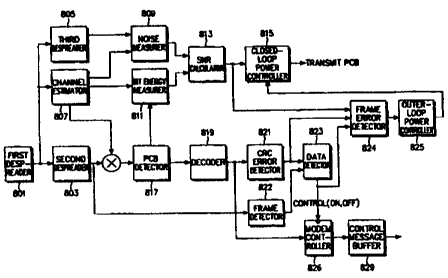
FIG. 8 is a block diagram of a receiver in a mobile station for outer-loop
power control while in DTX mode. The same components as shown in FIG. 3
will either be described briefly or not be described.
Referring to FIG. 8, a CRC error detector 821 determines whether frame
data received from a decoder 819 has errors and outputs a CRC error check
result
to a data detector 823 and a frame error detector 824. A frame detector 822
measures the energy of a DCCH to determine whether frame data exists or not
and feeds the measured energy to a data detector 823. If the measured energy
is
greater than a predetermined level, the data detector 823 determines that
frame
data exists and outputs a frame existence flag set to 1 to the frame error
detector
824. If no frame exists, the frame existence flag is set to 0. Upon receipt of
the
CRC error check result from the CRC error detector 821 and information
indicating the frame existence from the frame detector 822, the data detector
823
outputs an on/off control signal to a MODEM controller 826 and the frame error
detector 824. The data detector 823 will later be described in more detail in
connection with FIG. 11.
An SNR calculator 813 calculates an SNR from noise energy Nt received
CA 02337909 2001-01-17
WO 00/74289 PCT/KR00/00552
- 15-
from a noise measurer 809 and bit energy Eb received from a bit energy
measurer
811.
The frame error detector 824 receives the SNR from the SNR calculator
813, the CRC error check result from the CRC error detector 821, and the flame
existence flag message from the data detector 823 and determines whether frame
errors have been generated. The means of determination will be described in
detail with reference to FIG. 10A. If it turns out that frame errors exist,
the frame
error detector 824 outputs a frame error indicator to an outer-loop power
controller 825.
The . outer-loop power controller 825 performs an outer-loop power
control in the procedure shown in FIG. 7 and outputs a threshold to a closed-
loop
power controller 815. Then, the closed-loop power controller 815 performs a
closed-loop power control using the threshold.
The following description will be conducted with the appreciation that a
channel state measuring portion includes a channel estimator, a noise
measurer,
and a bit energy measurer, a frame decision portion includes a frame detector
and
a data detector, and an outer-loop power control portion includes a frame
error
detector and an outer-loop power controller.
FIG. 9 is a block diagram of a base station receiver for outer-loop power
control in a DTX mode according to an embodiment of the present invention.
Referring to FIG. 9, a decoder 923 outputs frame data to a CRC error detector
925 and a MODEM controller 933. The CRC error detector 925 determines
whether the frame data has errors and outputs a CRC error check result to a
data
detector 927 and a frame error detector 929. A frame detector 924 measures the
energy of a DCCH to determine whether frame data exists or not and feeds the
measured energy to the data detector 927. If the measured energy is greater
than
a predetermined level, the data detector 927 determines that frame data exists
and
outputs a frame existence flag set to 1 to the frame error detector 929. If no
fraine exists, the frame existence flag is set to 0. Upon receipt of the CRC
check
result from the CRC error detector 925 and the frame existence information
from
the frame detector 924, the data detector 927 outputs an on/off control signal
to
the MODEM controller 933 and the frame error detector 929. The data detector
927 will later be described in more detail with reference to FIG. 11.
CA 02337909 2001-01-17
WO 00/74289 PCT/KROO/00552
-16-
An SNR calculator 919 calculates an SNR from Nt measured from an
input signal in sub-chip units by a squarer 905 and an accumulator 907 and bit
energy Eb measured from the output of a third Walsh despreader 913 by an
accumulator 915 and a squarer 917.
The frame error detector 929 receives the SNR from the SNR calculator
919, the CRC error check result from the CRC error detector 925, and the frame
existence flag message from the data detector 927, and determines whether
frame
errors have been generated. A determination method will be described in detail
with reference to FIG. lOB. If it turns out that frame errors exist, the frame
error
detector 929 outputs a frame error indicator to an outer-loop power controller
931.
The outer-loop power controller 931 performs outer-loop power control
in the procedure shown in FIG. 7 and outputs a threshold to a closed-loop
power
controller 921. Then, the closed-loop power controller 921 performs closed-
loop
power control using the threshold.
A frame error detector according to the present invention can operate in
many ways. In the following description, two ways will be presented. The same
components in the forward and reverse link receivers will be described
referring
to FIG. 8.
Now, an embodiment of the frame error detector according to the present
invention will be described referring to FIGs. IOA and lOB. FIG. l0A
illustrates
input and output of the frame error detector according to the embodiment of
the
present invention and FIG. lOB is a detailed block diagram of the frame error
detector.
Referring to FIG. 10A, the frame error detector (824 or 929) outputs a
frame error indicator indicating the presence or absence of a frame error, for
the
input of an SNR, a CRC error check result, and a frame existence flag message.
In FIG. IOB, the frame error detector includes a frame error estimator
1003, a random number generator 1001, a look-up table 1004, and a switch 1005.
The look-up table 1004 tabulates FERs versus SNRs (Eb/Nt) as shown in FIG.
14B. The random number generator 1001 generates a random number NR under
the control of the frame error estimator 1003. As shown in FIG. 14A, the
random
numbers range from 0 to 1. The frame error estimator 1003, receives an SNR
CA 02337909 2001-01-17
WO 00/74289 PCT/KR00/00552
-17-
from the SNR calculator (813 or 919), adds a predetermined offset value to the
SNR to achieve a real SNR, reads an FER corresponding to the resulting SNR
with the offset (dB) added from the look-up table 1004, and stores the FER in
a
buffer (not shown). Then, the frame error estimator 1003 controls the random
number generator 1001 to generate a random number and determines whether the
generated random number is greater than the stored FER. If the random number
is not smaller than the FER, the frame error estimator 1003 considers that no
frame errors have occurred and outputs a frame error message '0' to the outer-
loop power controller (825 or 931). If the random number is smaller than the
FER, the frame error estimator 1001 considers that frame errors have been
generated and outputs a frame error message '1' to the outer-loop power
controller. The switch 1005 is switched by the frame existence flag message
received from the frame detector (823 or 927). If the frame existence flag
message is 1, the switch 1005 is switched to the CRC error check result and if
it
is 0, the switch 1005 is switched to the frame error estimator 1003.
FIG. 11 is a flowchart illustrating the operation of the data detector (823
or 927) for switching the switch 1005 shown in FIG. lOB.
Referring to FIG. 11, the data detector 823 determines whether frame
energy has been received from the frame detector 822 in step 1101. Upon
receipt
of the frame energy, the data detector 823 determines whether the frame energy
is
a predetermined level or greater in step 1103. If it is, the data detector 823
outputs a frame existence flag set to 1 to the switch 1005 in step 1105. If
the
frame energy is smaller than the predetermined level, the data detector 823
outputs the frame existence flag set to 0 to the switch 1005 in step 1107.
FIGs. 12A and 12B illustrate embodiments of a method of measuring the
SNR for one frame in the frame error estimator 1003 shown in FIG. 10B. In the
first embodiment, upon receipt of Nt and Eb in PCG units in step 1201, the
frame
error estimator 1003 obtains an average Eb (Eb, ave) and an average Nt (Nt,
ave)
for the entire frame in step 1203 and calculates an average SNR (SNR, ave)
from
Eb, ave and Nt, ave in step 1205. In the second embodiment, the frame error
estimator 1003 calculates an SNR (=Eb/Nt) for each PCG in step 1213 and an
average SNR (SNR, ave) for one frame in step 1215. The average SNR in the
first and second embodiments can be calculated respectively by
CA 02337909 2001-01-17
WO 00/74289 PCT/KR00/00552
-18-
Eb(1) + Eb(2) + = + &(N)
SNRq1e= Nt(l)+Nt(2)+ +Nt(N) ''''(1)
N~ (N)) N . . . . (2)
SNR~õ~ _ ( () + () + . .. + N
(1) N~(2) ( )
where N is the number of PCGs in one frame.
The SNR of one frame can be calculated in other ways.
If no frames have been received, a frame error can be estimated in many
ways, which will be described below.
FIG. 13 is a flowchart illustrating an embodiment of a frame error
estimation method when no frames have been received. Referring to FIG. 13, the
frame error detector 824 calculates an effective SNR by adding an offset value
to
an SNR calculated by Eb/Nt in step 1301. Since the measured SNR is different
from an SNR on the look-up table to some extent, this difference is
compensated
for by the offset.
In step 1303, the frame error detector 824 reads an FER (FERT)
corresponding to the SNR from the look-up table 1004 and stores the FER in the
buffer. In the look-up table, FERs are listed with respect to SNRs. Here, the
SNRs or the FERs can be arranged in predetennined intervals. In step 1305, the
frame error estimator 1003 controls the random number generator 1001 to
generate a random number (FERR). Upon receipt of the random number, the
frame error estimator 1003 compares the random number with FER,r in step 1307.
If the random number is smaller than FERY, the frame error estimator 1003
outputs a frame error message '1' to the outer-loop power controller 825 in
step
1309. If the random number is not smaller than FER., the frame error estimator
1003 outputs a frame error message '0' to the outer-loop power controller 825
in
step 1311.
FIG. 14A illustrates the range of random numbers generated with the
same probability by the random number generator. In FIG. 14A, the marked
portion indicates a uniform distribution of random numbers.
The table shown in FIG. 14B is made by calculating FERs versus SNRs
in an additive white Gaussian noise (AWGN) channel environment. It is obvious
that the table can be formed in other ways. An example of the FER tables in
the
CA 02337909 2001-01-17
WO 00/74289 PCT/KR00/00552
-19-
AWGN channel environment is shown below. Here, the table size (i.e., the
number of rows in the table) is 51.
(Table 1)
Eb/Nt FER Eb/Nt FER Eb/Nt FER
0.3526351 1.00000 0.7542624 0.53400 1.116122 0.02770
0.395774 0.99985 0.7719902 0.48465 1.141607 0.02005
0.4440143 0.99875 0.7899071 0.43265 1.167789 0.01605
0.4982825 0.99135 0.8078966 0.38990 1.195200 0.01160
0.5585475 0.96535 0.8269369 0.33690 1.224042 0.00925
0.5722369 0.95460 0.8457570 0.29075 1.253012 0.00655
0.5857184 0.93990 0.8651410 0.25510 1.279466 0.00475
0.5992779 0.91860 0.8853381 0.21730 1.309758 0.00405
0.6131983 0.89565 0.9066824 0.18165 1.340756 0.00295
0.6271264 0.87260 0.9268867 0.15640 1.372266 0.00265
0.6411836 0.84195 0.9492299 0.12670 1.404932 0.00205
0.6566134 0.80610 0.9709564 0.10860 1.437564 0.00125
0.6721940 0.77020 0.9933405 0.08365 1.504922 0.00075
0.6873548 0.72735 1.0175930 0.06525 1.575093 0.00055
0.7036301 0.67650 1.0406720 0.05500 1.649691 0.00010
0.7196916 0.63775 1.0645000 0.04285 1.726815 0.00005
0.7370404 0.58535 1.0900130 0.03605 1.769792 0.00000
The size of Table 1 can be changed when necessary. SNRs and FERs can
be arranged at predetermined intervals. A mobile station acquires the table in
many ways. Hereinbelow three of them will be described.
(1) A base station transmits the table to the mobile station on a common
channel like a broadcast channel and then the mobile station stores it in a
look-up
table storage.
(2) The base station transmits the table to the mobile station on a
dedicated channel which transmits a power control message and then the mobile
station stores it in the look-up table storage.
(3) The look-up table is stored in an internal memory of the mobile
station in a manufacturing process.
CA 02337909 2001-01-17
WO 00/74289 PCT/KR00/00552
-20-
Meanwhile, offset values used to compensate SNR measurements vary
with radio configurations (RCs), that is, code rates, and gating rates. Offset
values versus gating rates in a specific RC can be listed as shown below.
(Table 2) _
gating rate offset (dB)
1 -0.8
1/2 -1.2
1/4 -1.8
1/8 -3.0
Such a table as Table 2 can be given for each RC. The mobile station can
acquire the above table in many ways. Four of them will be presented below.
(1) A base station transmits the table to the mobile station on a common
channel like a broadcast channel and then the mobile station stores it in an
offset
table storage.
(2) The base station transmits the table to the mobile station on a
dedicated channel which transmits a power control message and then the mobile
station stores it in the offset table storage.
(3) The base station transmits a state transition command message
including an offset for corresponding state transition to the mobile station
and the
mobile station applies the offset.
(4) The offset table is stored in an internal memory of the mobile station
in a manufacturing process and a corresponding offset is applied according to
state transition.
FIG. 15 is a flowchart illustrating another embodiment of the frame error
estimation method when no frames have been received. In the second
embodiment, a frame error is estimated by comparing an SNR measured in frame
units with a fixed threshold or an externally received threshold. That is, if
the
measured SNR is smaller than the threshold, it is determined that frame errors
have been generated. If the SNR is greater than the threshold, it is
determined
that no frame errors have been generated. The comparison is performed in step
1501. The frame error estimator 1003 outputs the estimate to the outer-loop
CA 02337909 2001-01-17
WO 00/74289 PCT/KR00/00552
-21-
power controller 825 in steps 1503 and 1505
The threshold in the second embodiment is changed according to RCs
and gating rates. Thresholds versus gating rates in a specific RC are listed
below.
(Table 3)
gating rate threshold
1 0.7
1/2 0.61
1/4 0.53
1/8 0.49
Such a table as Table 3 can be made for each RC. The mobile station can
acquire the above table in many ways. Four of them will be presented below.
(1) The base station transmits the table to the mobile station on a
common channel like a broadcast channel and then the mobile station stores it
in
a threshold table storage.
(2) The base station transmits the table to the mobile station on a
dedicated channel which transmits a power control message and then the mobile
station stores it in the threshold table storage.
(3) The base station transmits a state transition command message
including a threshold for each corresponding state transition to the mobile
station
and the mobile station applies the threshold.
(4) The threshold table is stored in an internal memory of the mobile
station in a manufacturing process and a corresponding threshold is applied
according to state transition.
FIG. 16 is a flowchart illustrating a third embodiment of the frame error
estimation method when no frames have been received. In step 1601, the frame
error estimator 1003 compares an SNR measured in PCG units with a first
threshold or externally received. In step 1603, the frame error estimator 1003
increases the count number (N) of SNRs in PCGs smaller than the threshold by
one if the SNR is smaller than the threshold. The frame error estimator 1003
determines whether SNRs are completely measured in all PCGs of one frame in
CA 02337909 2001-01-17
WO 00%74289 PCT/KROO/00552
-22-
step 1605 and, if they are completely measured, the frame error estimator 1003
compares the count value (N) with a second threshold (Threshold2) in step
1607.
If the count value is greater than the second threshold in step 1607, the
frame
error estimator 1003 determines that frame errors have occurred and outputs a
frame error message ' 1' to the outer-loop power controller 825 in step 1609.
If
the count value is not greater than the second threshold in step 1607, the
frame
error estimator 1003 considers that no frame errors have been generated and
outputs a frame error message '0' to the outer-loop power controller 825 in
step
1611. The thresholds can be preset or received from the transmitter in
advance.
The thresholds used in the above third embodiment vary with RCs and
gating rates. A method of making a threshold table for the third embodiment
and
acquiring the threshold table in the mobile station is the same as that in the
second embodiment.
The mobile station can acquire the threshold table in many ways. Three
of them will be presented below.
(1) The base station transmits the table to the mobile station on a
common channel such as a broadcast channel and then the mobile station stores
it
in a threshold table storage.
(2) The base station transmits the table to the mobile station on the
dedicated channel that transmits a power control message and then the mobile
station stores it in the threshold table storage.
(3) The threshold table is stored in an internal memory of the mobile
station in a manufacturing process and a corresponding threshold is applied.
FIG. 17 illustrates gated transmission while in DTX mode according to
an embodiment of the present invention. Case 8-1 shows transmission at a
gating
rate of 1, case 8-3 shows transmission at a gating rate of 1/2, and case 8-5
shows
transmission at a gating rate of 1/4. PCBs are also gated at a corresponding
gating rate on a forward link. Even though gating occurs, the same effects as
produced from a no-gated transmission case are observed except that the number
of PCBs to be calculated is reduced. Therefore, the above-described outer-loop
power control methods can be applied to the gated mode, that is, the method of
changing a threshold by adapting an outer-loop power control based on the
CA 02337909 2001-01-17
WO 00/74289 PGT/KR00/00552
-23-
determination whether a real frame error is present or not only in a frame
transmission period, the method of perfonning an outer-loop power control
using
the determination whether a real frame error is present or not in a frame
transmission period and estimating the presence or absence of a frame error in
a
non-frame transmission period. Or the outer-loop power control may not be
applied in the gated mode.
FIG. 20 illustrates transmission of a DPCH while in DTX mode in an
asynchronous Japanese and European IMT-2000 system. DPCHs include a
DPDCH for data transmission and a DPCCH for recovering the DPDCH. The
DPDCH in turn includes a DCCH for logic control and a DTCH (Dedicated
Traffic Channel) for transmission of voice information. The DPCCH has a pilot
symbol for providing channel information and a TPC (Transmission Power
Control) for power control. There are four cases in the figure: (i)
transmission of
both the DPDCH and the DPCCH; (ii) non-transmission of DCCH information;
(iii) non-transmission of DTCH; and (iv) transmission of DPCCH only without
DPDCH. It is noted from the four cases that the DPCCH is continuously
transmitted. Therefore, a continuous outer-loop power control is possible
using
pilot symbols of the DPCCH, as stated before.
FIG. 19A is a block diagram of an embodiment of a reverse link receiver
which performs continuous outer-loop power control on a DPCH while in DTX
mode in an asynchronous IMT-2000 system according to the present invention.
The receiver is different from that shown in FIG. 18A in that a frame error
detector 1925 and an outer-loop power controller 1927 are further provided.
The
frame error detector 1925 outputs frame error infonnation to the outer-loop
power controller 1927, for the input of an SNR, a CRC error check result, and
information about the presence or absence of data (DPDCH). The operation of
the frame error detector 1925 is shown in FIGs. 10 and 11, and the operation
of
the outer-loop power controller 1925 in FIG. 7.
FIG. 19B is a block diagram of an embodiment of a forward link receiver
which performs continuous outer-loop power control on a DPCH while in DTX
mode in an asynchronous IMT-2000 system according to the present invention.
The receiver is different from that shown in FIG. 18B in that a frame error
detector 1969 and an outer-loop power controller 1971 are further provided.
The
frame error detector 1969 outputs frame error infonnation to the outer-loop
power controller 1971, for the input of an SNR, a CRC error check result, and
CA 02337909 2001-01-17
WO 00/74289 PCT/KR00/00552
-24-
information about the presence or absence of data (DPDCH). The operation of
the frame error detector 1969 has been described in connection with FIGs. 10
and
11, and the operation of the outer-loop power controller 1971 in connection
with
FIG. 7.
As described above, data communication is conducted in several states
according to the communication environment. For example, there are multiple
states, including a packet signal transmission state, a control signal only
transmission state, and a state where neither a packet signal nor a control
signal is
transmitted. In the first two states, transmission power is controlled by
closed-
loop power control and outer-loop power control.
A packet signal is transmitted according to a data communication state as
stated above. Data communication in an IMT-2000 system is comprised of an
active state, a control hold state, a dormant state, and so on. The above-
described
transmission control method is used in the active state and the control hold
state.
Specifically, a pilot signal and PCBs are transmitted in a gated mode in the
control hold state. According to gating rates 1/2, 1/4, and 1/8, many states
can be
defined. This is also applied to an active state and a control hold state in
an
asynchronous IMT-2000 system.
Power control at a gated transmission mode in the communication states
and the control hold state can be implemented in the following two
embodiments.
First Embodiment
When a communication state transitions to another communication state,
a threshold in the previous state is maintained in the transitioned state and
then
changed to a new threshold fit for the transitioned state through an outer-
loop
power control operation. For example, if a threshold incrementing step is
predetermined and the difference between a threshold before state transition
and
a threshold after state transition is greater than the step size, an outer-
loop power
controller changes the previous threshold to the threshold for the
transitioned
state in a predetermined time.
FIG. 21A is a block diagram of a mobile station receiver capable of
performing outer-loop power control with a reduced time for updating a
previous
threshold for a transitioned state in a synchronous CDMA mobile communication
system according to an embodiment of the present invention. The same
CA 02337909 2001-01-17
WO 00/74289 PCT/KR00/00552
-25-
components as shown in FIG. 8 will not be described.
An offset table storage 2133 includes an offset table as shown Table 4 in
which offsets are listed with respect to pre-transition and post-transition.
The
offsets are obtained empirically.
(Table 4)
before transition after transition offset (dB)
active gating rate 1/2 +2.5
active gating rate 1/4 +3.5
active gating rate 1/2 +6.0
gating rate 1/2 active -2.0
gating rate 1/2 gating rate 1/4 +1.0
gating rate 1/2 gating rate 1/8 +3.5
gating rate 1/4 active -3.5
gating rate 1/4 gating rate 1/2 -1.0
gating rate 1/4 gating rate 1/8 +2.5
gating rate 1/8 active -6.0
gating rate 1/8 gating rate 1/2 -3.5
gating rate 1/8 gating rate 1/4 -2,5
Table 4 can be made for each RC.
The reason for the difference in value and sign between the offsets for
transition of an active state to a 1/2 gated transmission state and for
transition of
the 1/2 gated transmission state to the active state is that a margin is added
to an
optimal threshold offset to ensure reception performance in producing a lower
threshold with an offset.
The offset table can be obtained in many ways. Four of them will be
presented below.
(1) A base station transmits the table to the mobile station on a common
channel like a broadcast channel and then the mobile station stores it in an
offset
table storage.
(2) The base station transmits the table to the mobile station on a
CA 02337909 2001-01-17
WO 00/74289 PCT/KR00/00552
-26-
dedicated channel which transmits a power control message and then the mobile
station stores it in the offset table storage.
(3) The base station transmits a state transition command message
including an offset for corresponding state transition to the mobile station
and the
mobile station applies the offset
(4) The offset table is stored in an internal memory of the mobile station
in a manufacturing process and a corresponding offset is applied according to
state transition.
An offset controller 2135 receives a higher layer message including
information about a pre-transition state and a post-transition state from a
higher
layer processor, reads an offset according to corresponding state transition
from
the offset table storage 2133, and feeds the offset to an outer-loop power
controller 2137. The offset controller 2135 receives an offset table from a
base
station through an upper layer message and stores it in the offset table
storage
2133. The offset controller 2135 stores the received offset table only in an
initial
state and does not store later received offset tables. Or it updates the
offset table
in handoff and stores the updated offset table. In addition, if the base
station
transmits only an offset for the corresponding state transition, the offset
controller
2135 detects the offset from a higher layer message and directly output it to
the
outer-loop power controller 2137.
The outer-loop power controller 2137 adds the offset received from the
offset controller 2135 to a pre-transition offset and outputs a fixed
threshold to a
closed-loop power controller 2119.
FIG. 21B is a block diagram of a mobile station receiver capable of
performing outer-loop power control with a reduced time for updating a
previous
threshold for a transitioned state in an asynchronous CDMA mobile
communication system according to an embodiment of the present invention.
The same components as shown in FIG. 8 will not be described.
The mobile station receiver for the asynchronous CDMA mobile
communication system is the same on structure as that for the synchronous
CDMA mobile communication system shown in FIG. 21A. An offset table
storage 2181 includes an offset table as shown in Table 4. Upon receipt of
state
CA 02337909 2001-01-17
WO 00/74289 PCT/KR00/00552
-27-
transition information through an upper layer message from a higher layer
processor, the offset table storage 2181 reads a corresponding offset from the
offset table and outputs the offset to an outer-loop power controller 2185.
Then,
the outer-loop power controller 2185 adds the offset received from an offset
controller 2183 to a pre-transition threshold and outputs a fixed threshold to
a
closed-loop power controller 2171.
FIG. 22A is a block diagram of a base station receiver in the synchronous
IMT-2000 system according to an embodiment of the present invention. The
components of the base station receiver except for an offset controller 2239
are
the same as those shown in FIG. 9. The offset controller 2239 operates in the
same manner as the offset controller 2135 shown in FIG. 21A. An offset table
for the offset controller 2239 of the base station is stored in a memory or
received
from a system network.
FIG. 22B is a block diagram of a base station receiver in the
asynchronous IMT-2000 system according to an embodiment of the present
invention. Due to the nature of the asynchronous IMT-2000 system, the base
station receiver operates in the same manner as the mobile station receiver
shown
in FIG. 21B. An offset controller 2281 operates in the same manner as the
offset
controller 2183 shown in FIG. 21B. An offset table such as mentioned in
reference to FIG. 22A is used.
Second Embodiment
Gated transmission aims at reduction of interference and power
consumption by transmitting only a control signal (pilots and PCBs) in a gated
mode when no traffic signals to be transmitted exist in a control hold state.
Traffic signals to transmit are seldom generated in the control hold state.
Accordingly, only control signals are transmitted in a gated mode in most
cases.
To ensure the reception performance of a traffic signal transmitted in the
gated
transmission mode, the transmission power of a control signal and the traffic
signal should be set higher than in an active state. In an embodiment of the
present invention, the transmission power of a control signal transmitted in a
gated mode is maintained the same as in an active state. In this state, when a
traffic signal to transmit is generated, the gain of the transmission power of
the
traffic signal is controlled, and, when no traffic signals exist, the
transmission
power is minimized. Consequently, the reception performance of the traffic
signal is ensured.
CA 02337909 2001-01-17
WO 00/74289 PCT/KR00/00552
-28-
FIG. 23 is a block diagram of a transmitter in a synchronous IMT-2000
base station operated in a gated transmission mode in a control hold state
according to an embodiment of the present invention. A description of the same
components as shown in FIG. 1 will be omitted.
Referring to FIG. 23, a gain adjustment table 2329 has a gain adjustment
table in which gains are listed with respect to transmission power levels of a
traffic signal to be controlled according to communication states and gating
rates.
The gain adjustment table can be empirically obtained and shown as Table 5 by
way of example.
(Table 5)
gating rate gain adjustment value (dB)
1/2 +2.5
1/4 +3.5
1/8 +6.0
Table 5 can be made for each RC.
A gain adjustment controller 2305 reads a transmission power gain
adjustment value for a traffic signal from the gain adjustment table storage
2329
based on information about a communication state and a gating rate received
from a higher layer processor and feeds the gain adjustment value to a
multiplier
2323 which acts as a gain adjuster. The gain adjuster 2323 adjusts the
transmission power gain of the traffic signal with the gain adjustment value
received from the gain adjustment controller 2305, while establishing a path
for
transmitting a control message or blocking the control message from being
transmitted according to a gain control signal received from a MODEM
controller 2303 as stated earlier with reference to FIG. 1.
FIG. 24 is a block diagram of a transmitter in a synchronous IMT-2000
mobile station operated in a gated transmission mode in a control hold state
according to an embodiment of the present invention. A description of the same
components as shown in FIGs. 2 and 23 will be omitted.
Referring to FIG. 24, a gain adjustment table storage 2431 may acquire a
gain adjustment table in one of the four ways described referring to FIG. 21A.
CA 02337909 2001-01-17
WO 00/74289 PCT/KROO/00552
-29-
FIG. 25B is a block diagram of a transmitter in an asynchronous IMT-
2000 base station operated in a gated transmission mode in a control hold
state
according to an embodiment of the present invention. A description of the same
components as shown in FIG. 23 will be omitted.
Referring to FIG. 25B, the rate converter 2517 changes the rate of the
output signal of the encoder 2515 to that of the input signal of the
interleaver
2519 by repeating or puncturing the output of the encoder 2515 when the rate
at
the output of the encoder 2515 is different from that at the input of the
interleaver
2519.
FIG. 26B is a block diagram of a transmitter in an asynchronous IMT-
2000 mobile station operated in a gated transmission mode in a control hold
state
according to an embodiment of the present invention. A description of the same
components as shown in FIGs. 24 and 25B will be omitted.
As described above, the present invention is advantageous in that (1)
since an outer-loop power control is possible even for a non-data transmission
period while in DTX mode, an accurate threshold for outer-loop power control
can be obtained when a data frame is generated; (2) transmission power can be
saved and frame errors can be decreased due to the accurate threshold; (3)
time
required to converge a pre-transition threshold to a post-transition threshold
in an
outer-loop power control operation is reduced through threshold compensation;
(4) the decrease of the convergence time prevents power consumption involved
in
the convergence and reduces frame errors; and (5) transmission power is
minimized in the absence of a traffic signal to be transmitted in a gated
transmission mode and in the presence of a traffic signal to be transmitted,
the
reception performance of the traffic signal is ensured.
While the invention has been shown and described with reference to
certain preferred embodiments thereof, it will be understood by those skilled
in
the art that various changes in form and details may be made therein without
departing from the spirit and scope of the invention as defined by the
appended
claims.