Note: Descriptions are shown in the official language in which they were submitted.
CA 02337924 2001-02-23
FIELD OF THE INVENTION
The invention relates to an aircraft passenger cabin structure
equipped with facilities for optimizing the number of passengers
that can be transported on a given cabin floor space in commer-
cial passenger aircraft.
BACKGROUND INFORMATION
Conventionally, passengers must sit on special passenger seats
in commercial passenger aircraft. At least during the starting
and landing phase of an aircraft, passengers must be seated and
tied down by safety belts in order to assure a sufficient safety
in case of a crash or a rough landing. Even during cruising
flight it is desirable that passengers remain in their seats due
to the limited space available in aircraft aisles and service
facilities such as toilets. Furthermore, when an aircraft during
flight must pass through a turbulent weather condition, passen-
gers are more quickly secured in their seats if they are already
sitting in their seats. Thus, it is essential for the comfort
of a passenger that the aircraft seats within the cabin are
secured to the cabin floor with a sufficient spacing from one row
, of seats to the next and that each seat provides a comfortable
seat width in the direction perpendicularly to the flight direc-
tion.
However, requiring that all passengers should be seated at all
times does not result in a most efficient space utilization
- 2 -
CA 02337924 2001-02-23
within the aircraft cabin. Thus, it is the aim of airlines to
maximize the number of passengers relative to an available cabin
floor space in order to minimize the transport costs per passen-
ger. The requirement of an optimal comfort and safety for the
passengers is not necessarily compatible with a second require-
ment of maximizing the number of passengers per available cabin
floor space to minimize costs. Thus, a compromise solution is
required. Such a compromise leads to optimally utilizing the
available cabin floor space for each passenger in such a way that
the space allocated for each passenger is sufficient while sell-
ing that space or seat for a justifiable price is possible.
U. S. Patent 5,611,503 discloses an example of an involved calcu-
lating method for developing seating configurations or cabin lay-
outs in the passenger cabin of a commercial aircraft, whereby the
calculations aim at optimizing the comfort under varying condi-
tions such as changing occupancy rates while simultaneously
maximizing the number of passenger seats per available floor
space. That seating row and column configuration which provides
the highest passenger comfort is then installed in the passenger
cabin.
German Patent Publication DE 195 34 024 C2 discloses a seating
group or row of seats for a passenger cabin of an aircraft. The
width of the individual seats can be widened when a passenger
takes up a seat. When the seats are not used the seats can be
narrowed, thereby to at least temporarily provide for a wider
aisle and to provide more comfort for passengers who occupy a
- 3 -
CA 02337924 2001-02-23
widened seat next to a narrowed seat which is not occupied.
Please see also U. S. Patent 5, 829, 836 (Schumacher et al.) corre-
sponding to the above German Patent DE 195 34 024 C2.
Conventional seating arrangements in passenger cabins of aircraft
are all based on passenger sizes which require a minimal seat
width in the direction perpendicularly to a longitudinal aircraft
axis or flight direction and which require a minimal spacing
between rows of seats in the direction of the longitudinal air-
craft axis. These requirements permit calculating the maximum
number of passenger seats for any given floor space in a passen-
ger cabin. Only in those instances where not all seats have been
sold for a particular flight, is it possible to widen the indi-
vidual passenger seats for at least some passengers to thereby
increase their comfort.
German Patent Publication DE 198 14 548 discloses an effort to
reduce the space provided per passenger in passenger ground
transportation vehicles such as buses, railroad cars or ferries.
Seating supports are mounted in a frame structure, whereby the
seat dimension in the facing direction of a user is relatively
short. The backrest is an elastic flat component also secured
to the frame structure. The backrest thus forms an elastic
impact protection for a passenger seated in a row of seats behind
a given row of seats. Such an arrangement is legally not permit-
ted in an aircraft due to governmental safety regulations which
are so strict that passengers in an aircraft, as opposed to
passengers in ground transportation vehicles, must be seated in
- 4 -
CA 02337924 2001-02-23
special aircraft seats capable of taking up defined accelerations
in the horizontal and vertical directions. Moreover, aircraft
seating arrangements must be capable of absorbing energy in case
of a crash. Under conventional transport conditions it is not
possible to transport aircraft passengers in a standing room
fashion which has, for example, been possible for a long time in
buses, rail vehicles and ferries.
OBJECTS OF THE INVENTION
In view of the foregoing it is the aim of the invention to pro-
1o vide the following objects singly or in combination:
to minimize the space required for transporting a passenger
in an aircraft cabin to thereby maximize the number of passengers
for any given cabin floor space;
an optimal comfort shall be provided in combination with a
maximum floor space utilization in an aircraft cabin while still
providing a sufficient mobility for the aircraft passengers;
to satisfy the legal safety regulations for aircraft passen-
gers in case of a crash and during turbulent flights;
to facilitate the boarding and deplaning of a passenger
aircraft;
- 5 -
CA 02337924 2006-11-29
to provide passenger stands in a standing room area of a
passenger aircraft whereby such stands shall be adaptable to
passengers of different sizes; and
to make passenger seat tickets less expensive particularly
if two tickets are time shared tickets whereby one ticket is for
a passenger stand and the other ticket is for a passenger seat
so that two persons can alternately use either the seat or the
stand.
SUMMARY OF THE INVENTION
A passenger aircraft according to the invention comprises a cabin
structure which is equipped with a standing room area having a
clearance between floor and ceiling sufficient for passenger
stands installed in the standing room area for transporting
passengers in a standing position during starting, during flight
and during landing of the aircraft in the gravity field of the
earth. Each passenger stand is equipped with at least one pas-
senger backing for taking up accelerations to which a passenger
may be exposed, including horizontal andjor vertical accelera-
tions. Each stand is further equipped with a safety device, more
specifically a safety belt, preferably a so-called three-point
safety belt system.
The invention provides a completely new transport concept for the
floor space utilization in aircraft passenger cabins by using
- 6 -
CA 02337924 2006-11-29
passenger stands in a standing room area of passenger aircraft,
whereby the space.requirements per passenger can be minimized and
accordingly, the total number of passengers that can be trans-
ported is maximized. Each passenger stand is provided with a
passenger backing mounted to at least one upright post and the
backing or the stand is equipped with a safety device so that the
- 6a -
CA 02337924 2001-02-23
required safety requirements are satisfied at all times including
during starting and landing of an aircraft and during turbulent
flights, even if the passengers are secured in an upright posi-
tion. The safety device and the backing combine to hold the
standing passenger in place.
By combining seating arrangements with passenger stands on the
available floor space of a passenger cabin, the cabin layout is
flexibly adaptable to various requirements and an optimal space
utilization within the cabin is achieved.
A plurality of passenger stands may be arranged in the standing
room area of the cabin in rows and columns, whereby passengers
do not have to come out of their seats for deplaning or can
readily assume their stands to thereby speed up the boarding
procedure.
1s By preferably arranging the passenger backing in the stand so
that the passenger using the stand faces substantially opposite
to the flight direction, the safety is increased because forces
that occur during a crash or rough landing force the passenger
against the backing with his back over a large surface area,
whereby the risk of injury is reduced because the loads per body
surface area unit of the passengers' body are reduced.
By providing two upright posts the passenger backing can be
arranged between these upright posts and any safety belts may be
secured either to the posts or to the backing, whereby the safety
- 7 -
CA 02337924 2001-02-23
is even increased, compared to the safety provided by conven-
tional seating arrangements. Further, by using one post for
mounting the backing the angular position of the backing relative
to the flight direction is easily adjusted. Such adjustment is
also possible where two posts are used to which the backing is
secured by adjustable brackets.
By providing the passenger stand with an auxiliary seat support,
the passenger stands can be used for prolonged periods of time
because a passenger may rest his or her legs while resting on an
auxiliary seat secured to the backing or the post or posts.
BRIEF DESCRIPTION OF THE DRAWINGS
In order that the invention may be clearly understood, it will
now be described in connection with example embodiments, with
reference to the accompanying drawings, wherein:
Fig. 1 is a plan view of a cabin floor space in a pas-
senger aircraft showing a combination of passen-
ger seats and passenger stands according to the
invention;
Fig. 2 is a perspective view into a cabin space in the
flight direction illustrating passenger stands
arranged in rows and columns;
- 8 -
CA 02337924 2001-02-23
Fig. 3 is a schematic view in the direction of the arrow
III in Fig. 2 illustrating several possible angu-
lar positions of the present passenger stand
particularly its passenger backing relative to
the flight direction;
Fig. 4A is a front view of an embodiment of a passenger
stand mounted on two upright posts;
Fig. 4B is a side view of the present passenger stand
equipped with an auxiliary seat shown in its use
position; and
Fig. 4C is a view in the direction of the arrow IIIC in
Fig. 4A and showing two passenger stands arranged
in a column.
DETAILED DESCRIPTION OF PREFERRED EXAMPLE EMBODIMENTS AND OF THE
BEST MODE OF THE INVENTION
Fig. 1 shows a plan view of one example layout according to the
invention in a passenger aircraft cabin section 1 having a
floor 1A and walls 2. The cabin layout has two areas. A first
area 4 alongside the cabin walls 2 holds conventional passenger
seats PS. A second standing room area 5 holds passenger stands 3
to be occupied by passengers P in an upright position. Only one
column of stands 3 is shown along each seating row. However,
- 9 -
CA 02337924 2001-02-23
several rows and columns of stands 3 may be arranged in different
layouts.
Passengers P in the seats PS face in the forward or flight direc-
tion FWD. On the other hand, passengers P in the stands 3 face
in the opposite direction as indicated by a respective arrow A.
The stands 3 are preferably slightly slanted relative to the
forward direction FWD as will be explained in more detail below
with reference to Fig. 3. The required minimum spacing between
the passenger seats PS in the forward or flight direction FWD is
noticeably larger than the minimum spacing between the stands 3
in the same direction.
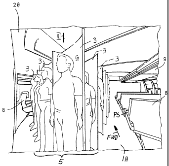
Fig. 2 shows that the passenger seats PS are arranged in rows 8
below luggage compartments 9 where the clearance between the
cabin floor 1A and the luggage compartments 9 is insufficient for
a standing room. The standing room is provided between the
rows 8 of seats PS where the clearance between the floor 1A and
the ceiling 2A is sufficient for this purpose. As shown in Fig.
2 there are four stands 3 arranged in rows and the rows in turn
are arranged in columns extending in the forward flight direction
FWD. The arrangement is such that the passengers in the seats
PS face in the forward direction while the passengers in the
stands 3 face in the opposite direction. In Fig. 2 the individ-
ual stands 3 are constructed as shells 6 that are rigidly or
adjustably secured to the floor 1A and to the ceiling 2A. Cer-
tain of the rows of stands 3 in the standing room area 5 may be
- 10 -
CA 02337924 2001-02-23
replaced by rows 8 of seats PS so that rows of stands 3 and
rows 8 of seats alternate with each other.
Referring further to Fig. 2 it may be necessary to avoid luggage
compartments in the standing room area to provide the required
clearance. However, each stand may be provided with its own
luggage compartment.
As shown in Fig. 2, the stands 3 are constructed as shells 6 that
provide the respective backing for each passenger individually
at all times, but particularly during landing and starting as
well as during turbulent flight. Each shell 6 defines the up-
right position of a passenger using the stand 3. The backing in
the form of a shell 6 is preferred for privacy reasons. However,
any construction of a support rest or support or backing wall can
be used for the present purposes. Additional safety devices such
as belts are secured to the stands 3 as will be described in more
detail below. Each stand may be further equipped with space for
emergency equipment, such as a life vest, safety instructions,
and a display for such instructions or the like as well as com-
fort equipment such as reading lamps, call buttons and the like.
Displays are positioned in or on the forward facing side of a
backing 3 so that the passenger in the next row can see it. The
arrangement of the stand 3 in rows and columns as shown in Fig. 2
provides for an optimal utilization of the floor space 1A since
each passenger stand 3 requires less space than a respective
seat.
- 11 -
CA 02337924 2001-02-23
Fig. 3 shows the arrangement of a stand 3 at 900 relative to the
forward flight direction FWD, whereby the passenger P faces in
the opposite direction. The passenger will be held against the
backing 6' constructed in this example as a flat wall. Movement
of the passenger in any other direction will be restrained by
belts to be described with reference to Figs. 4A, 4B and 4C.
Securing the passenger to the backing 6' reduces the risk of
injury to standing passengers against bumping into other cabin
components.
The backing 6' can be locked to the floor by a lock L in any one
of a plurality of angularly adjusted positions as shown in dashed
lines. A minimum slant relative to the forward direction FWD
should be at least 30 , preferably 60 . The lock L engages any
one of a plurality of holes H in the floor if it is desired to
slant the backing 6' relative to the forward direction FWD. For
this purpose the backing 6' is secured to a vertical post VP.
The adjustability of the angle of the backing 6' relative to the
flight direction FWD can be achieved in several ways. For exam-
ple, the vertical post VP may be secured in bearings in the cabin
floor and in the ceiling. In this embodiment the backing 6'
would be rigidly secured to the vertical post VP. In a modifica-
tion the vertical post VP would be rigidly secured to the floor
and ceiling while the backing 6' is rotatably secured to the
vertical post. In both instances the lock L could be a locking
bar, preferably a spring-biased locking bar, that can be lifted
out of a locking hole H by a handle and pressed onto the hole by
a spring-biasing force.
- 12 -
CA 02337924 2001-02-23
Further example embodiments of the construction of the stand 3
are shown in Figs. 4A to 4C, which show an embodiment in which
each stand 3 has a backing shell 11 secured to two upright posts
and 10' to form a support structure 7. The shell 11 does not
5 need to reach all the way to the floor 1A. Preferably, the shell
11 has a back portion against which the back of a passenger is
held by a seatbelt system 14, preferably a three-point seatbelt
system having connection points 15A, 15B and 15C secured to the
shell 11 and/or the upright posts 10, 10' as shown in Fig. 4A.
10 Fig. 4B shows the shell 11 preferably provided with an auxiliary
seat 16, which is preferably a folding seat permitting a passen-
ger to rest his or her feet. The seat 16 is preferably adjust-
able along one or two guide rails as indicated by an arrow Al.
A locking mechanism of conventional construction permits locking
the seat in several positions at different elevations above the
floor 1A to accommodate passengers of different sizes.
For the same reason the mounting point 15A of the seatbelt 14 is
preferably adjustable in a guide slot up or down as indicated by
an arrow A2.
The upright posts 10, 10' are rigidly secured to the floor lA and
to the ceiling 2A at a horizontal spacing from each other best
seen in Fig. 4C. The horizontal spacing is sufficient for fully
supporting the back of a passenger. Fig. 4C also shows the
arrangement of two passenger stands 3 with their support struc-
tures 7 in a column.
- 13 -
CA 02337924 2001-02-23
Fig. 4C further shows that the shell 11 is formed with at least
one, preferably two, side portions 11A that provide some privacy
relative to neighboring support structures 7 in a row and rela-
tive to an aisle. The side portions ilA face in the direction
opposite to the flight or forward direction FWD.
Although the invention has been described with reference to
specific example embodiments, it will be appreciated that it is
intended to cover all modifications and equivalents within the
scope of the appended claims. It should also be understood that
the present disclosure includes all possible combinations of any
individual features recited in any of the appended claims.
- 14 -