Note: Descriptions are shown in the official language in which they were submitted.
CA 02338302 2001-02-27
FUEL LEVEL INDICATOR FOR PROPANE TANK ON A BARBECUE
This invention relates to a fuel level indicator for a propane tank
located on a barbecue.
Gas fired barbecues, most using propane as a fuel source, have a
5 tank containing gas under pressure. In barbecues used for domestic
purposes, the fuel supply in propane tanks lasts for many months and,
depending on usage, can even last for one or more years. The tanks do not
have a fuel level indicator and when a tank becomes empty, there is no
prior warning. In almost all cases, the food being barbecued will not be
fully cooked when the gas supply runs out. For this reason, many
consumers keep a spare tank on hand. However, tools are required to
remove the empty tank and replace it and, depending on how well
organized the consumer is, that process could take 5 minutes or it could
take 30 minutes or even more time. In the meantime, the food that was
15 being barbecued will have cooled off and other parts of the meal that are
being prepared on something other than the barbecue might well be
overcooked.
The problem of not having a fuel level indicator has existed for
some time and, while there are other ways of detecting the fuel level in a
2o tank containing gas under pressure, it is desirable to have an indicator
that
does not require any tools to install or remove and does not require any
adjustment to be made by the user of the barbecue once a full tank has
been installed until it is desirable to remove that tank.
It is an object of the present invention to provide a fuel level
25 indicator for a propane tank mounted on a barbecue where the indicator
can be installed or removed without tools and no adjustments or changes to
the operation of the barbecue are required from the time that a full tank is
installed on the barbecue until a nearly empty tank is removed.
CA 02338302 2001-02-27
A fuel level indicator for use with a barbecue and a tank containing
gas under pressure, said top having a substantially centrally located
circular opening therein to receive the tank. The top is large enough to
extend beyond the tank. The fuel level indicator has at least three support
posts extending between the top and the base. Each support post has a
spring thereon located between the top and the base. The springs are sized
to have sufficient force so that when a full tank is placed on the top, the
top will slide downward along the bolts while compressing the springs so
that the top and base are very close to one another. The springs are sized
1 o so that as the tank empties, the springs extend until the tank is nearly
completely empty when the springs have extended to such an extent that
the top has almost returned to its original position before the tank was
installed.
Preferably, there is a scale located on the indicator to display
~ 5 whether the tank is nearly full or nearly empty or at some point in
between.
A propane tank, barbecue and fuel level indicator in combination.
In the drawings:
Figure 1 is a perspective view of the fuel level indicator of the
20 present invention;
Figure 2 is a side view of a propane tank on the fuel level indicator
where the tank is nearly full;
Figure 3 is a side view of a tank on the indicator where the tank is
nearly empty;
25 Figure 4 is a front view of a tank on the fuel level indicator;
Figure 5 is a front view of a barbecue, fuel level indicator and tank
where the fuel level indicator has a remote indicator accessory;
Figure 6 is a side view of a fuel level indicator, tank and barbecue
in combination where the fuel level; and has a remote indicator.
_2_
CA 02338302 2001-02-27
Figure 7 is a side view of a fuel level indicator made out of plastic
material.
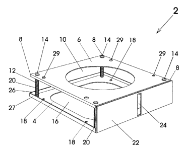
In Figure 1, a fuel level indicator 2 has a base 4 and top 6. The top
6 has a generally square shape with four corners 8. An opening 10 that is
5 preferably centrally located in the top 6 is sized to receive a base of a
propane tank (not shown in Figure 1 ). At each of the four corners 8, there
is located a bolt 12 having a head 14. Each of the bolts 12 extends through
a hole (not shown in Figure 1) that is large enough to readily receive the
bolt yet small enough so that the head 14 of each bolt will not pass through
1o the hole. The holes (not shown in Figure 1) are large enough so that the
top can slide upward and downward along each of the bolts. The bolts 12
are anchored in the base which conforms generally with the shape of the
top 6. The base 4 has a central portion 16 that is cut away and has
mounting holes 18 for mounting the base onto a barbecue (not shown in
15 Figure 1 ). Surrounding each of the bolts 12 are springs 20 that are
substantially identical to one another. The springs 20 extend between the
base 4 and the top 6. When there is no tank resting on the top 6, the
springs are in a fully extended position with the top 6 resting against the
heads 14. While springs with other specifications could be used, it has
2o been found that four springs that each have a primary load specification of
six pounds at 2.5 inches and a secondary load of 10.5 pounds at 1.0 inches
are suitable for the purposes of the present invention. The base 4 has a
front face 22 thereon containing an elongated opening 24. The elongated
opening 24 has a scale thereon to indicate full ("F") and empty ("E") at the
2s bottom and top respectively thereof. Preferably, there is an upturned
flange 26 along a rear and upturned flanges 27 along each side of the base
4 to provide additional strength to the base 4. The holes 29 are located in
vertical alignment with the holes 18 to allow a screwdriver to be inserted
-3-
CA 02338302 2001-02-27
through the holes 29 in order to turn screws into the barbecue (not shown)
through the holes 18.
In Figures 2, 3 and 4, the same reference numerals are used to
describe those components that are identical to those components of Figure
5 1 without further description unless indicated. In Figure 2, a propane tank
30 that is almost full of propane (not shown) is mounted on the fuel level
indicator 2. It can be seen that a base 32 of the tank 30 extends through
the top 6 so that the remainder of the tank 30 rests on said top. It can be
seen that the weight of the tank compresses the springs 20 so that the top 6
to slides down the bolts 12 and the base 32 of the tank 30 is almost touching
the base 4 of the fuel level indicator 2. In Figure 3, the same reference
numerals are used to describe those components that are shown in Figure 2
without further description unless otherwise indicated. The tank 30 is
nearly empty and it can be seen that the top 6 is at a much higher level
15 than the top 6 of Figure 2. In Figure 3, the top 6 is almost in contact
with
the heads 14 of the bolts 12.
In Figure 4, the same reference numerals are used to describe those
components that are identical to those in Figures 2 and 3 without further
description unless otherwise indicated. In Figure 4, it can be seen that the
2o top 6 provides an indicator in the elongated opening 24 to show that the
tank 30 is part way between full and empty. A pointer could be mounted
to the top 6 to extend into the elongated opening 24 where the pointer
would function as an indicator.
In Figures 5 and 6, the same reference numerals are used as those
25 used in Figures 1 to 4 to describe those components that are identical
without further description. It can be seen that a conventional gas
barbecue 34 has a frame 36 with a lower shelf 38. The fuel level indicator
2 is preferably attached to the lower shelf 38 by screws through the
mounting holes 18 (not shown in Figures 5 and 6). The amount of fuel
-4-
CA 02338302 2001-02-27
remaining in the tank 30 can be determined using the scale on the
elongated opening 24. However, the barbecue 34 has an added feature of a
remote level indicator 40. The remote level indicator 40 is optional and
provides a second scale 42 on an upper portion of the barbecue where it
5 can be more easily read by an operator. While the scale 42 is shown to be
resting in midair in Figure 6, it could be affixed to an upper shelf 44 or it
could be otherwise affixed to an upper part of the frame 36. The remote
level indicator 40 has an upper bellows 46 and a lower bellows 48. The
lower bellows 48 is located beneath the propane tank 30 and is preferably
to centrally located between the tank 30 and the base 4. A tube 50 extends
from the lower bellows 48 through the second scale 42 to the upper
bellows 46. The lower bellows 48 and the tube 50 up to part of the second
scale 42 are filled with colored liquid 52. The remaining part of the tube
in the upper bellows contain air. The bellows 46, 48 and tube 50 constitute
15 a closed system. When a full propane tank is placed on the top 6 of the
fuel level indicator 2 the top 6 will be forced downward toward the base 4
thereby compressing the lower bellows 48. The compression of the lower
bellows 48 will cause a colored liquid to flow toward the upper bellows 46
and the liquid will then move to a point near a top 54 of the second scale
20 42. As the tank 30 empties the top 6 of the fuel indicator will move
upward and the lower bellows 48 will expand thereby dropping the level of
the liquid 54 on the second scale 42. Ultimately, when the tank 30 is
nearly empty, the liquid on the scale will be at the nearly empty indicator
at a bottom 56 of the second scale 42. The purpose of the upper bellows
25 46 is to receive the air that is forced out of the tube 50.
In Figure 7, there is shown a side view of a fuel level indicator 60,
which is made out of plastic. A base 62 is molded with the posts 64, lip 66
and font panel 68 in one piece. A top 70, also made out of plastic, is a
separate piece, which is placed on the posts 64 (only two of which are
-5-
CA 02338302 2001-02-27
shown) and held in place by retainers (not shown) that fit into a groove
(not shown) on each post. The springs on each post 64 have been omitted
from Figure 7.
An advantage of the fuel indicator of the present invention is that
5 after the fuel indicator is installed on the barbecue, no tools are required
to
install or remove the tank from the fuel indicator. Of course, tools will be
required to connect the tank to the gas supply line of the barbecue in the
same conventional manner as tanks are presently connected. Further,
when a tank has been installed on the fuel indicator 2, the barbecue is
to operated in exactly the same way as existing barbecues are operated.
Since most of these barbecues are portable, they are moved from place to
place. Many of the barbecues have wheels at one end of the frame so that
barbecues can be moved into a garage or other storage area when they are
not being used. Further, the fuel indicator of the present invention is not
15 connected in any way to the gas supply from the tank and the use of the
tank is as safe with the indicator 2 of the present invention or with the
remote indicator 40 as it would be with a conventional barbecue and
propane tank with no indicator.
While the tank is described as a propane tank, other fuels under
2o pressure within a tank can also be used with the indicator of the present
invention. Also, the fuel indicator is not required to be installed or located
on the barbecue. The fuel indicator could be located on the ground beside
the barbecue with the propane tank located on top of the fuel indicator and
connected to the barbecue.
-6-