Note: Descriptions are shown in the official language in which they were submitted.
CA 02338371 2001-O1-22
WO 00/12949 PCT/US99/01741
Floating Bypass Seai
for Rotary Regenerative Heat Exchangers
Background of the Invention
The present invention relates to means for reducing or eliminating
the internal bypassing of gas streams around the heating elements in
rotary regenerative heat exchangers and particularly relates to the
internal bypassing of air and flue gas streams around the heating
elements in an air preheater.
In a rotary regenerative air preheater, the rotor is divided up into
pie-shaped sectors, which are in turn subdivided into rotor
compartments. Each rotor compartment is designed to accommodate
one or more assemblies of heating elements comprising basket-like
containers and heat transfer surfaces therein. Because of fabrication
tolerances and/or the distortion of the rotor structure associated with
extended operation under varying thermal conditions, it is usually
necessary to design the heating elements to allow a clearance around
each basket so as to avoid interference at installation.
When fabrication tolerances, rotor distortion and/or design
ctearances result in excessive gaps ("bypass gaps"1 between the sides
of the basket and the corresponding side wall of the rotor compartment .
or adjacent basket, a portion of the air and gas streams will flow
through the gaps thereby bypassing the heat transfer surfaces and
thereby resulting in a loss in heat transfer efficiency.
Bypass gaps have been addressed in the past by a practice known
as"tabbing" which entailed the welding of bypass strips over gaps
deemed large enough to close, or with resilient sealing devices installed
in gap areas large enough to accept them. Both of these approaches are
costly in field labor expense and/or material. Generally, every layer of
heating elements needs to be tabbed or sealed individually.
CA 02338371 2001-O1-22
WO 00/12949 PCT/(TS99/01741
2
Summary of the Invention
The present invention provides a unique means to reduce or
eliminate air and gas flow bypass around the heat transfer surfaces in
rotary regenerative heat exchangers. The invention involves the use of
floating seals placed in the rotor compartments adjacent the ends of the
heating elements and around the periphery of the heating elements
ends. The floating seals are sized to fit each compartment with minimal
clearance whereby the seals bridge the gaps between the heating
elements and the sides of the compartments. The seals may be
adjustable to accommodate various sized compartments. A modification
includes deformable edge seals attached to two or more sides of the
floating seals whereby the edge seals are deformed to conform to the
walls when the floating seals are pressed into position.
Brief Description of the Drawings
Figure 1 is a generalized perspective view of a typical rotary
regenerative air preheater showing the rotor sectors and compartments.
Figure 2 is a cross section elevation through one sector of a
portion of a rotor illustrating conventional heating elements stacked
vertically in one of the compartments and showing the bypass gap.
Figure 3 is a plan view of a rotor compartment of the prior art
containing a heating element and illustrating the bypass gaps.
Figure 4 is a perspective view of one of the floating seals of the
present invention.
Figure 5 is a partial elevation cross section of a rotor similar to
Figure 2 but illustrating a compartment with the floating seal of the
present invention in position between the heating elements.
Figure 6 is a partial plan view of a rotor illustrating a compartment
containing a heating element and a floating seal.
Figure 7 shows an adjustable modification of the floating seal.
CA 02338371 2001-O1-22
WO 00/12949 PCT/US99/01741
3
Figure 8 is a side view of a modified floating seal with deformable
edge seals.
Figure 9 is a side view illustrating the modified floating sea! of
Figure 8 in a compartment with the edge seals deformed.
Figures 10, 1 1 and 12 show three types of heating elements.
Description of the Preferred Embodiments
in the description of the present invention, rotary regenerative air
preheaters which are used for transferring heat from flue gas to
combustion air will be used as the example. However, it is to be
understood that the invention is applicable to any rotary or stationary
regenerative heat exchangers. Figure 1 of the drawing illustrates a
partially cut-away perspective view of such a conventional air preheater
showing a housing 12 in which a rotor 14 is mounted on drive shaft or
post 16 for rotation as indicated by the arrow 18. The rotor has an
outer shell 20 and a plurality of radially extending diaphragms 22
dividing the rotor into the pie-shaped sectors 24. The tangential plates
26 divide each sector 24 into the generally trapezoidally-shaped
compartments 28. The outermost compartments usually have a curved
outer end defined by the rotor shell 20. Although not shown in this
Figure 1, each compartment contains a plurality of stacked heating
elements. The housing of the air preheater is divided. by the plate 30
into a flue gas side and an air side. A corresponding center section is
located on the bottom of the unit. The hot flue gases enter the air
preheater through the inlet duct 32, flow axially through the rotor where
heat is transferred to the heat transfer surface and then exit through the
gas outlet duct 34. The countercurrent flowing air enters through the
air inlet duct 36, flows through the rotor 14 and picks up heat and then
exits through the air outlet duct 38.
CA 02338371 2001-O1-22
WO 00/12949 PCT/US99/01741
4
Figure 2 is an elevation cross section of a portion of the rotor of
Figure 1 basically showing one sector with the radial diaphragm 22
extending between the rotor post 16 and the rotor shell 20. The
tangentially extending plates 26 together with the diaphragms 22 form
the compartments 28. This Figure 2 illustrates two heating elements 40
stacked in one of the compartments 28. However, it will be understood
that there will be heating elements in each of the compartments and
that there may be more or less than two heating elements stacked in
each compartment. This Figure 2 illustrates the tangential gaps 42
between the elements and the tangential plates 26.
In order to further illustrate the problem with prior designs, Figure
3 is a plan view showing a heating element 40 in a compartment 28
bounded by the diaphragms 22 and the tangential plates 26. As can be
seen, there are radial gaps 44 between the sides of the heating element
40 and the diaphragms 22 and the tangential gaps 42 between the inner
and outer ends of the heating element 40 and the tangentiat plates 28
as also shown in Figure 2.
There are basically two types of conventional heating elements
40. One type is commonly referred to as a picture frame style basket
140 having only a frame 142 around each of its four vertical faces as
shown in Figure 10. The heat transfer surface consisting of a large
number of individual plates 144 parallel to the inner and outer ends is
installed in the basket. With this type of basket, the air and gas can
escape through the sides of the heating element into the bypass gap
either above or below any tabbing which may be installed. The other
general type of heating element is typically referred to as a full wrapper
basket 240 with each of the four vertical faces being closed by a
continuous plate 242 wrapped around the basket as shown in Figure 11.
Since the sides and ends are all closed, there can be no escape of air or
gas from the inside to the outside of each individual heating element.
CA 02338371 2001-O1-22
WO 00/12949 PCT/US99/01741
Another type of closed heating element 340 is a hybrid of the picture
frame type and the full wrapper type. It has a picture frame basket 342
but the four vertical faces have plates 344 attached to the frame to
close off the sides as shown in Figure 12. With any of these types of
5 heating elements, the bypass gap is a problem. With respect to the
present invention, baskets of any style will work, however, use of the
present invention with baskets of the closed type such as the full
wrapper basket of Figure 11 or the picture frame type with side plates
' of Figure 12 will produce preferential results.
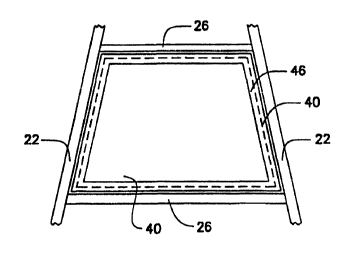
Figure 4 shows a floating bypass seal 46 in accordance with the
present invention. This seal 46 is generally a trapezoidal shaped frame
sized to fit a given rotor compartment 28 with minimal clearance. There
are various sized seats to fit the various sized compartments. Also, the
seals for the outermost compartments may have a curved outer end to
7 5 conform to the curved rotor shell 20. The sizes of the floating bypass
seals are selected for the various sized compartments such that they ara
capable of being inserted into the compartments with any clearance
being minimized taking into consideration the tolerances on the
compartment sizes and any expected distortion. The width of the sides
~ 48 of the seals 46 is selected such that there will be continuous
engagement with the upper or lower perimeter of any given heating
element 40. The thickness of the seats 46 is selected to be substantial
enough for handling, for installation into the compartments and for
withstanding any loading induced by the adjacent heating elements.
Figure 5 is an elevation cross section of a portion of a rotor
illustrating the floating bypass seal 46 of the present invention located
in position in a compartment between the heating elements 40. As can
be seen, the floating bypass seat essentially extends out to the
tangential plates 26 to close off the gap 42. Figure 6 is another
showing of the floating bypass seal 46 in position overlying a heating
CA 02338371 2001-O1-22
WO 00/12949 PC'T/US99/01741
6
element 40. The periphery of the heating element 40 is shown in
dotted line below the seal 40. It can be seen that the seal extends out
to the sides of the compartment with minimal clearance and that the
seal overlaps the heating element 40 to form a flow restriction and
essentially close the gap. As can be seen in the Figure 5, the floating
bypass seal 46 is sandwiched between the two heating elements 40.
Therefore, the seal, which is typically free floating, cannot be blown out
of position such as when soot blowing pressures are applied-. During
installation of the seal, it may be advantageous to at least temporarily
fasten the seal in position in the compartment. This can be done by
welding such as tack welding along at least one side. This may
facilitate the assembly even though the tack welds may later break due
to the forces created such as by thermal expansion.
Since some air preheaters may have corresponding compartments
28 in various sectors 24 which vary in size, either due to manufacturing
tolerance or thermal deformations, Figure 7 shows a modified floating
bypass seal 50 which is adjustable. This floating bypass seal is
subdivided into segments identified as 52 which are connected to each
other by the sliding coupling means 54. The coupling means 54 which
are illustrated are merely heavy sheet metal bent around the joints
between the segments to hold the segments together while permitting
the segments to slide within the coupling means. However, other forms
of coupling means could also be used in the present invention. For
example, the ends of the segments could have openings into which a
coupling bar is slidably inserted thereby bridging the joints. After
assembly of the four segments 52 with the coupling means 54, the
floating bypass seal 50 is installed in a compartment 28 and then
adjusted outward so that the segments engage the radial and tangential
plates or, in the case of the outermost compartment, engage the rotor
SUBSTITUTE SHEET (RULE 26)
CA 02338371 2001-O1-22
WO 00/12949 PCT/US99/01741
7
shell. This assures that the clearances between the floating bypass
seals and the walls of the compartments are always minimal.
Another embodiment of the invention is shown in Figures 8 and
9. In this embodiment, the floating bypass seal, now identified as 56,
consists of a base frame 58 which is sized to fit a rotor compartment
with a slightly increased but still small clearance. Attached to the base
frame 58 is a deformable edge seal 60 which may be on all four sides
as shown in Figure 8 or may only be on fewer than four sides. This
deformable edge seal may be attached by any suitable means such as
welding and may be formed from any light gauge metal strip which is
capable of being deformed to conform to the shape of the compartment
walls. For installation, this modified floating bypass sea! 5B is
positioned in the intended compartment, usually at an angle, and then
pressed down into position in engagement with the top of a heating
element. In the process of pressing the seat into position, the edge seal
60 is deformed to essentially form a continuous engagement between
the seal and the compartment wall as shown in Figure 9.