Note: Descriptions are shown in the official language in which they were submitted.
CA 02338407 2001-02-26
EXTERNAL LIQUID LEVEL GUAGE
FIELD OF THE INVENTION:
[0001 ] This invention relates to liquid level measuring devices, and
particularly
relates to external liquid level gauges for determining the level of the
interface between
a mass of flowable material and the void volume above it within a container.
BACKGROUND OF THE INVENTION:
[0002] Liquid level measuring devices have been known for many years. Their
purpose is to locate the level of a flowable material, or to indicate the
amount of flowable
material remaining in a container.
[0003] On many occasions, monitoring the amount of flowable material in a
container is required. However, direct observation of the flowable material
level is not
always possible or practical. Measurement of the material in such containers
as
pressurized cylinders, sealed containers, cryogenic flasks, and opaque vessels
is often
difficult. Such measurements are even more troublesome when the material
within the
container is corrosive or potentially toxic or flammable.
[0004] Sight glasses and weight scales are some examples of liquid level
measuring devices which are commonly employed. Both of these devices suffer
from
a number of disadvantages. Sight glasses are expensive, irremovable from one
container
to another, and they can crack and break easily. Furthermore, on such
occasions where
the container is placed outdoors, ultraviolet light can cause the glass to
haze. Vv'eight
scales also are expensive and they generally are non-transferable. In many
instances,
measurements provided by weight scales are inexact.
[0005] A simple, economical external liquid level gauge which permits a direct
reading of the level of a flowable material has been provided by the present
inventor in
1
CA 02338407 2001-02-26
the prior art. This liquid level measuring device is a significant improvement
from sight
glasses and weight scales. It can be repeatedly removed and reattached to the
outside
wall of a container. In addition, it requires no alteration of the container
or the use of
tools or other auxiliary equipment.
[0006] While the external liquid level gauge provided in the prior art
comprises
only one thermochromatic material, the present invention is directed at an
external liquid
level gauge with at least two thermochromatic materials. Each thermochromatic
material
is disposed entirely along the length of the gauge which is adapted to be
affixed vertically
to the outside wall of the container. Since each thermochromatic material
responds
chromatically within a different temperature range, a slight change in
temperature in the
region of the external liquid level gauge can be readily discerned visually by
a vivid color
change.
[0007] The theory is that the rate of heat transfer is different between a
mass of
flowable material and the void volume above it such that for any container
with a modest
I 5 heat conducting capability, the container wall experiences a temperature
gradient which
is most pronounced at the interface of the contents with the void volume above
the
contents, and of course below that interface. That is to say, the rate of heat
transfer
through the wall of a container will be greater where there is a mass of
flowable material
located in the container than where there is a void volume above the flowable
material.
In other words, the temperature of the container wall changes most abruptly at
the level
of the interface, and below. Thus, with the use of thermochromatic materials,
a vivid
color change occurring at the interface , and below, will permit an observer
to obtain a
direct reading of the level of the flowable material within a container by
discerning where
the interface is located.
[0008] As employed herein, the term "flowable material" is intended to mean
any
fluidic matter in which the shape of a given mass depends on the container but
the
volume is independent thereof. "Flowable material" is also intended to mean
any fluidic
2
CA 02338407 2001-02-26
matter which seeks a level and offers no permanent resistance to change of
shape. The
term may include any mass of granular material which has fluidic properties.
[00] The expression "thermochromatic materials" as used herein is intended
to mean materials that have or exhibit different colors or shades of color at
different
temperatures. The expression "responding chromatically" as used herein is
intended to
mean having or exhibiting different colors or shades of color at different
temperatures.
DESCRIPTION OF THE PRIOR ART:
[0010] United States Patent No. 3,696,675 issued September 20, 1971 to
GILMOUR teaches an external liquid level gauge adapted to be permanently
affixed to
the outside wall of a container for determining the liquid-gas interface
within the
container. The external liquid level gauge described in this patent consists
of a uniform
thermochromatic liquid crystalline material which coats the entire base layer
of the gauge
such that it is at right angles to the liquid-gas interface. The uniform
thermochromatic
material covers the entire temperature range to which the container is
subjected within
an overall range of -20°C to 250°C. Depending upon the
thermochromatic material
selected, color changes over a gradient from violet to red can occur in a
range as small
as 2°C to one as broad as 150°C. Since the temperature
differential across the liquid-gas
interface is generally small, on the order of less than 2°C, the change
in color is slight
across the interface. This is particularly the case when the container is
placed outdoors
and a large temperature range needs to be covered. As a result, it is
difficult to visually
locate the liquid-gas interface.
[00I 1 ] An improvement to the external liquid level gauge as taught in
Gilmour
'675 patent is disclosed in United States Patent No. 4,358,955 which issued to
the present
inventor, RAIT, on September 29. 1980. Here, the thermochromatic coated base
layer
is magnetically mounted to the outside wall of the container, and thus the
external liquid
level gauge can be repeatedly removed and replaced or relocated when
necessary.
3
CA 02338407 2001-02-26
SUMMARY OF THE INVENTION:
[0012] In accordance with one aspect of the present invention, there is
provided
an external liquid level gauge for externally determining the level of the
interface
between a mass of flowable material and the void volume above it within a
container.
The external liquid level gauge of the present invention is adapted to be
affixed vertically
to the outside wall of the container, extending along substantially the entire
height.
[0013 ] In accordance with the present invention, the flowable material within
the
container has fluidic properties and it has a faster rate of heat transfer
than the void
volume above it within the container.
[0014] The external liquid level gauge. which is in the form of an elongated
strip,
comprises a layer of base material and a layer of thermochromatic materials.
The base
layer is adapted to be secured to the outside wall of the container and is
such that it is in
an intimate heat transfer relationship with the outside wall of the container.
The
thermochromatic layer overlies the layer of base material.
[0015] The thermochromatic layer comprises a light absorbing background and
at least two regions of thermochromatic materials which are arranged upon the
light
absorbing background. The regions of at least two thermochromatic materials
are
disposed in arrays thereof and are arranged entirely along the length of the
external liquid
level gauge, in the vicinity between the bottom end and the top end.
Furthermore, each
of the thermochromatic materials is arranged in an individual area and each
thermochromatic material responds chromatically within a different operating
temperature range.
[0016] The flowable material within the container may be chosen from the group
consisting of water, alcohol, oil, coffee, tea, juice, milk, liquefied gas and
granular
material.
4
CA 02338407 2001-02-26
[0017] In keeping with the present invention, the container to which the
external
liquid level gauge is adapted to be affixed may be chosen from the group of
containers
consisting of pressurized cylinders, open containers, sealed containers,
cryogenic flasks
and opaque vessels.
[0018] Typically, but not necessarily, the base material has adhesive or
magnetic
properties so as to permit the external liquid level gauge to be repeatedly
removed and
reattached to the container.
[0019] The external liquid level gauge may also include an ultra-violet filter
layer
which overlies the layer of thermochromatic materials.
[0020] The thermochromatic materials, in keeping with the present invention
may
be chosen from the group consisting of cholesteryl oleate, cholesteryl oleyl
carbonate and
mercurous oxide.
[0021 ] At least two thermochromatic materials in an array may have
overlapping
operating temperature ranges. Moreover, each of the thermochromatic materials
in an
array displays a color gradient within its operating temperature range.
[0022] Each thermochromatic material upon the light absorbing background is
arranged in an individual array which may be chosen from the group of
geometric
configurations consisting of dots, circles, stars, squares, triangles, arrows,
semi-circles,
pentagons, hexagons, digits and letters.
[0023] In a particular embodiment of the present invention, the regions are
arranged upon the light absorbing background such that one of the regions is
positioned
vertically down the center of the external liquid level gauge and at least one
other region
is arranged diagonally on each side.
[0024] In another embodiment of the present invention, the regions are
arranged
vertically in at least one array.
[0025] In yet another embodiment of the present invention, the regions are
arranged diagonally in at least one array.
5
CA 02338407 2001-02-26
[0026] Still further, in another embodiment, the regions are arranged
horizontally.
[0027] Typically, but not necessary, at least two adjacent regions are
arranged to
form a set and each set comprises at least two thermochromatic materials.
Furthermore,
each set is disposed vertically along the entire length of the external liquid
level gauge
in a repeated manner.
[0028] A further object of the present invention is to provide a method of
determining the level of the interface between a mass of flowable material and
the void
volume above it within a container using an external liquid level gauge
affixed to the
outside wall of the container. The external liquid level gauge would be, of
course, as
described above. The method comprises the steps of:
(i) inducing heat transfer between the external liquid level gauge and the
mass of flowable material within the container.
(ii) discerning visually a color change in at least one region of the array of
the
external liquid level gauge.
[0029] The region noted above which responds chromatically to a temperature
change is contiguous to the mass of flowable material within the container.
Specifically,
step (i) may be achieved by any of the steps chosen from the group of steps
consisting
of:
(a) spraying a liquid onto the entire surface of the external liquid level
gauge.
(b) wetting the entire surface of the external liquid level gauge with a
moistened cloth or sponge.
(c) pouring a liquid down the entire surface of the external liquid level
gauge.
(d) trickling a liquid down the entire surface of the external liquid level
gauge.
(e) applying an electrically energized source along the entire length of the
external liquid level gauge.
6
CA 02338407 2001-02-26
[0030] In one embodiment of the present invention, the liquid as employed
above
in any of steps (a) through (d) is a heat source. Since the temperature of the
liquid is
above the temperature of the flowable material within the container, heat
transfer is
induced from the liquid to the flowable material.
[0031 ] In another embodiment of the present invention, the liquid as employed
above in any of steps (a) through (d) is a heat sink. Here, the temperature of
the liquid
is below the temperature of the flowable material within the container, thus
heat transfer
is induced from the flowable material to the liquid.
[0032] Particularly when at least two adjacent regions of the external liquid
level
gauge are arranged to form a set and when a plurality of such sets are
disposed in a
repeated manner vertically along the length of the external liquid level
gauge, the method
of determining the level of the interface between a mass of flowable material
and the
void volume above it within a container may also further comprise the step of:
(iii) estimating the level of the interface between the mass of flowable
material and the void volume above the mass of flowable material within
the container using the external liquid level gauge where the estimated
area falls between a level having a profound color change and a level
having a faint color change.
[0033] These and other objects of the present invention are discussed in
greater
detail hereafter, in association with the accompanying drawings.
BRIEF DESCRIPTION OF THE DRAWINGS:
[0034] The novel features which are believed to be characteristic of the
present
invention, as to its structure, organization, use and method of operation,
together with
further objectives and advantages thereof, will be better understood from the
following
drawings in which a presently preferred embodiment of the invention will now
be
illustrated by way of example. It is expressly understood, however, that the
drawings are
7
CA 02338407 2001-02-26
for the purpose of illustration and description only and are not intended as a
definition
of the limits of the invention. Embodiments of this invention will now be
described by
way of example in association with the accompanying drawings in which:
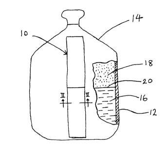
[0035] Figure 1 is a front view of an external liquid level gauge in keeping
with
the present invention, when affixed to the outside wall of a container;
[0036] Figure 2 is a transverse sectional view taken on line II-II of the
external
liquid level gauge in keeping with the present invention as shown in Figure l,
greatly
enlarged;
[0037] Figure 3 is a front view of the thermochromatic array of a first
embodiment of the external liquid level gauge in keeping with the present
invention;
[0038] Figure 4 is a front view of the thermochromatic array of a second
embodiment of the external liquid level gauge in keeping with the present
invention;
[0039] Figure 5 is a front view of the thermochromatic array of a third
embodiment of the external liquid level gauge in keeping with the present
invention;
[0040] Figure 6 is a front view of the thermochromatic array of a fourth
embodiment of the external liquid level gauge in keeping with the present
invention;
[0041 ] Figure 7 is a front view of the thermochromatic array of a fifth
embodiment of the external liquid level gauge in keeping with the present
invention,
when affixed to the outside wall of the container; and
[0042] Figure 8 is a front view of the thermochromatic array of a sixth
embodiment of the external liquid level gauge in keeping with the present
invention,
when affixed to the outside wall of the container.
DETAILED DESCRIPTION OF THE PREFERRED EMBODIMENTS:
[0043] The novel features which are believed to be characteristic of the
present
invention, as to its structure, organization, use and method of operation,
together with
8
CA 02338407 2001-02-26
further objectives and advantages thereof, will be better understood from the
following
discussion.
[0044] As noted above, a feature of the present invention is essentially to
provide
an external liquid level gauge for externally determining the level of the
interface
between a mass of flowable material and the void volume above it within a
container.
[0045] Referring first to Figure 1, a front view of an external liquid level
gauge
is shown. The external liquid level gauge 10 is affixed vertically to the
outside wall
12 of a container 14, extending along substantially the entire height. The
external liquid
level gauge 10 is in the form of an elongated strip; it is in an intimate heat
transfer
10 relationship with the outside wall 12 of the container 14.
[0046] The container 14 is shown as being partially filled with a flowable
material 16. The flowable material 16 is in intimate contact with the interior
surface of
the wall 12 and a void volume 18 is above the interface 20 of the flowable
material 16.
[0047] The flowable material 16 within container 14 has fluidic properties,
and
it has a faster rate of heat transfer than the void volume 18 above it. A
typical flowable
material 16 within the container 14 may be water. Other flowable materials
that may be
found within the container 14 may be alcohol, oil, coffee, tea, juices, milk,
liquefied
gases-particularly such as carbon dioxide-or even granular materials.
[0048] It is noted that the container 14 to which the external liquid level
gauge
10 is affixed may be a pressurized cylinder, an open container, a sealed
container, a
cryogenic flask, or an opaque container.
[0049] The external liquid level gauge 10 comprises a layer of base material
30
and a layer of thermochromatic materials 31 with reference to Figure 2. The
base layer
is adapted to be secured to the outside wall 12 of the container 14 and is
such that it
25 is in an intimate heat transfer relationship with the outside wall 12 of
the container 14.
Typically, the base layer 30 has adhesive or magnetic properties so as to
permit the
9
CA 02338407 2001-02-26
external liquid level gauge 10 to be repeatedly removed and reattached to the
container
14. The thermochromatic layer 31 overlies the layer of base material 30.
[0050] The thermochromatic layer 31 comprises a light absorbing background
34 and at least two regions 36 (Figure 3) of thermochromatic materials 32
which are
arranged upon the light absorbing background 34. The regions 36 of at least
two
thermochromatic materials 32 are arranged entirely along the length ofthe
external liquid
level gauge 10, in the vicinity between the bottom end and the top end.
Furthermore,
each of the thermochromatic materials 32 is arranged in an individual area 38
(not
shown). The external liquid level gauge 10 may also include an ultra-violet
filter layer
40 which overlies the layer of thermochromatic materials 31.
[0051] Thermochromatic materials 32 made by the Thermochromatic Liquid
Crystal division of Thermographic Measurements Limited may be effectively
employed.
The thermochromatic materials 32 used are preferably reversible or
thermotropic.
Cholesteric liquid crystal compounds are most suitable. These compounds behave
mechanically like liquids but exhibit the optical properties of crystals. They
exhibit vivid
color changes with only slight changes in temperature.
[0052] The thermochromatic materials 32 cover the entire temperature range to
which the container 14 is subjected, within an overall range of -20°C
to 250°C. Some
examples of thermochromataic materials 32 which may be employed are
cholesteryl
oleate, cholesteryl oleyl carbonate, and mercurous oxide. Each thermochromatic
material
32 responds chromatically within a different operating temperature range.
Cholesteryl
oleate has an operating temperature range between 32.2°C to
63.9°C while cholesteryl
oleyl carbonate has an operating temperature range between 29.2°C to
39.2°C.
Furthermore, each of the thermochromatic materials 32 displays a color
gradient within
its operating temperature range.
[0053] Typically, the light absorbing background 34 is a dark background. The
light absorbing background 34 absorbs any light transmitted through the
CA 02338407 2001-02-26
thermochromatic material 32 and allows selectively reflected light to be
observed without
light interference. Since each thermochromatic material 32 responds
chromatically
within a different temperature range, the selectively reflected light is
determined by
orientation change of the thermochromatic material 32 in response to
temperature.
[0054] The additional ultra-violet filter layer 40 prevents the deterioration
of the
external liquid level gauge 10. It has been reported that long and continuous
exposure
to ultraviolet radiation causes the thermochromatic materials 32 to
deteriorate and lose
their temperature responsive chromatic characteristic which is necessary for
the purpose
of utilization as a liquid level gauge as described herein. This is
particularly the case
when the container 14 is placed outdoors where it is subjected to sunlight for
a long
period of time.
[0055] Depending upon the thermochromatic material 32 selected, color changes
over a gradient can occur in a range as small as 2°C to one as broad as
150°C. For a
thermochromatic material 32 with a large operating temperature range, the
color
difference across the interface 20 is small.
[0056] As noted above, the rate of heat transfer is different between the mass
of
flowable material 16 and the void volume 18 above it such that for any
container 14 with
a modest heat conducting capability, the container wall 12 experiences a
temperature
gradient which is most pronounced at and below the interface 20 between a mass
of
flowable material 16 and the void volume 18 above it within a container 14. In
other
words, the temperature of the container wall 12 changes most abruptly at and
below the
level of the interface 20.
[0057] In an outdoor environment, the container 14 may be subjected to varying
temperatures, from below 0°C to over 37.8°C. In that particular
case, the best results
may be achieved by using five to seven different thermochromatic materials 32
in the
external liquid level gauge 10 where each thermochromatic material 32 has an
operating
temperature range of about 8°C. In more stable environments such as a
residence or an
11
CA 02338407 2001-02-26
office-or even in stores, warehouses, and factories-where temperatures often
fall
between 16°C to 29°C, two to five thermochromatic materials 32
are most effective. In
such environments where temperatures range from about 16°C to
27°C, two
thermochromatic materials 32 with an operating temperature range of about
8°C or five
thermochromatic materials 32 with each having an operative temperature range
of about
3°C may also be effectively employed.
[0058] Moreover, the operating temperature ranges of at least two
thermochromatic materials 32 in the external liquid level gauge 10 may be
overlapped.
A temperature response may be invoked from two thermochromatic materials 32 in
the
external liquid level gauge 10, thus making the level of the interface 20
between a mass
of flowable material 16 and the void volume 18 above it within a container 14
easier to
observe. For instance, the upper operating temperature of one thermochromatic
material
32a may be 10°C, the temperature differential across the interface 20
may be 2°C, and
the temperatures of the mass of flowable material 16 and the void volume I 8
above it
within the container 14 may be 9°C and 11 °C respectively. On
such occasion, a color
change occurs for the end of the thermochromatic material 32a which responds
to the
lower operating temperature range while a color change also occurs for the
adjacent end
of the thermochromatic material 32b which responds within the higher operating
temperature range. In order to determine the level of the interface 20,
readings of both
thermochromatic materials 32a and 32b are necessary. If two thermochromatic
materials
32 having overlapping operating temperature ranges are employed, the level may
be
readily discerned visually.
[0059] Turning now to Figures 3 through 6, the regions 36 of at least two
thermochromatic materials 32 are disposed in arrays thereof, designated by
reference
numerals 50, 52, 54, and 56.
[0060] Although not shown in the figures, each of the thermochromatic
materials
32 is arranged upon the light absorbing background 34 in an individual area 38
which
12
CA 02338407 2001-02-26
may have any of the following geometric configurations such as dots, circles,
stars,
squares, triangles, arrows, semi-circles, pentagons, hexagons, digits, and
letters.
[0061] As can be seen in Figure 3, the thermochromatic array 50 comprises five
thermochromatic materials 32a, 32b, 32c, 32d, and 32e which are arranged in
respective
regions 36a, 36b, 36c, 36d and 36e. The region 36a is positioned vertically
down the
center of array 50. Regions 36b and 36c are arranged on one side of the
vertically
positioned region 36a while regions 36d and 36e are arranged on the other side
of region
36a. The four regions 36b, 36c, 36d, and 36e are arranged in a diagonal
manner,
repeatedly over the length of array 50. Thermochromatic material 32a has the
lowest
operating temperature range of the group of thermochromatic materials 32 found
in array
50 while thermochromatic materials 32b and 32c have the next two highest
operating
temperature ranges, and thermochromatic materials 32d and 32e have the two
most
highest operating temperature ranges. The separation of the regions 36b, 36c,
36d, and
36e by region 36a provides a visual breadth between the lowest and highest
temperatures
to which array 50 may respond. Furthermore, it is preferred that the
thermochromatic
material 32a with the lowest operating temperature range exhibits a "cool"
color such as
blue and the thermochromatic material 32e with the highest operating
temperature range
exhibits a "hot" color such as red to aid in the locating of the interface 20
between the
mass of flowable material 16 and the void volume 18.
[0062] For achieving the best results on outdoor use, each thermochromatic
material 32 responds within a different operating temperature range,
preferably of about
8°C. The five thermochromatic materials 32a, 32b, 32c, 32d and 32e are
chosen such
that the full range of all the operating temperature ranges covers the range
of
temperatures to which array 50 may be most likely exposed.
[0063 ] For optimum results, the upper temperature of thermochromatic material
32a may slightly overlap the lower limit of the operating temperature range of
thermochromatic material 32b, and so on with each additional thermochromatic
material
13
CA 02338407 2001-02-26
32 within array 50 sequentially to the thermochromatic material 32e which has
the
highest operating temperature range. For instance, by using this overlap
system, a color
change occurs in two adjacent thermochromatic materials 32a and 32b when the
temperature at the interface 20 bridges the two thermochromatic materials 32a
and 32b.
Thus, the interface 20 is readily discerned visually.
[0064] When the external liquid level gauge 10 is placed indoors where the
atmosphere is often controlled and potential temperature variations are
generally much
smaller than outdoors, the thermochromatic materials 32 in the array 50 may be
chosen
such that they have operating temperature ranges within the possible outer
limits for
thermochromatic materials 32 but also such that they have operating
temperature ranges
as small as 3°c.
[0065] Referring now to Figure 4, a different embodiment of the present
invention is shown. Thermochromatic array 52 comprises five thermochromatic
materials 32a, 32b, 32c, 32d and 32e which are arranged in respective regions
36a, 36b,
36c, 36d and 36e vertically upon the light absorbing background 34.
[0066) In another embodiment of the present invention shown in Figure 5, the
thermochromatic array 54 comprises five thermochromatic materials 32a, 32b,
32c, 32d
and 32e which are disposed along the light absorbing background 34 in
respective
regions 36a, 36b, 36c, 36d and 36e. Here, the regions 36a, 36b, 36c, 36d and
36e are
arranged in a diagonal manner, repeatedly over the entire length of array 54.
The angle
along the longitudinal axis of array 54 that the diagonal regions 36a, 36b,
36c, 36d and
36e are disposed may vary, but is preferably 45°. As can be seen
particularly in Figure
5 and the following Figure 6, at least two adjacent regions 36 are combined to
form a set
39 and a plurality of such sets 39 are disposed in a repeated manner
vertically along the
length of the external liquid level gauge 10.
[0067] Finally, referring to Figure 6, the regions 36a, 36b, 36c, 36d and 36e
comprising thermochromatic materials 32a, 32b, 32c, 32d and 32e respectively
of array
19
CA 02338407 2001-02-26
56 are arranged in a horizontal manner. As noted above, the five regions 36a,
36b, 36c,
36d and 36e combine to form a set 39 and a plurality of such a set 39 are
disposed along
the length of array 56.
[0068] In keeping with the provisions of the present invention, applicant
herein
provides a method of determining the level of the interface 20 between a mass
of
flowable material 16 and the void volume 18 above it within a container 14
when the
external liquid level gauge 10 is affixed to the outside wall 12 of the
container 14.
[0069] In a steady state ambient environment, it is possible that little or no
temperature differential exists at the interface 20 between the mass of
flowable material
16 and the void volume 18 within the container 14. The addition or withdrawal
of
thermal energy to or from the container 14 and the mass of flowable material
16 is
required to cause a temperature differential across the interface 20 to occur,
and thus
inducing a color change response from the thermochromatic materials 32 in
turn. As
noted above, the void volume 18 above the mass of flowable material 16
generally
absorbs or releases far less thermal energy than the mass of flowable material
16, causing
a measurable temperature differential at the interface 20.
[0070] Thus, the method of determining the interface 20 between the mass of
flowable material 16 and the void volume 18 first comprises the step of
inducing heat
transfer between the external liquid level gauge 10 and the mass of flowable
material 16
within the container 14. The occurrence of a temperature differential across
the interface
20 will then induce a color change in at least one region 36 of the array of
the external
liquid level gauge 10, allowing the interface 20 to be readily discerned
visually.
[0071 ] Specifically, the first step which involves the induction of heat
transfer
may be carried out by any of the steps chosen from the group of steps
consisting of:
(a) spraying a liquid onto the entire surface of the external liquid level
gauge
10;
CA 02338407 2001-02-26
(b) wetting the entire surface of the external liquid level gauge 10 with a
moistened cloth or sponge;
(c) pouring a liquid down the entire surface of the external liquid level
gauge
10;
(d) trickling a liquid down the entire surface of the external liquid level
gauge
10;
(e) applying an electrically energized source along the entire length of the
external liquid level gauge 10.
[0072] When the liquid as described above is a heat source, the temperature of
the liquid is above the temperature of the flowable material 16 within the
container 14,
thus heat transfer is induced from the liquid to the flowable material 16.
Indeed, steam
from a steam gun may be employed if a large temperature gradient between the
heat
source and the flowable material 16 is desired. On the other hand, when the
liquid is a
heat sink, the temperature of the liquid is below the temperature of the
flowable material
16 within the container 14, thus heat transfer is induced from the flowable
material 16
to the liquid.
[0073] For the purpose of illustration, a large sealed container 14 with an
external
liquid level gauge 10 affixed to its outside wall 12 is placed in a warehouse
or factory
where the temperature generally falls between 5°C and 35°C. The
five thermochromatic
materials 32a, 32b, 32c, 32d and 32e of the external liquid level gauge 10 are
arranged
in respective regions 36a, 36b, 36c, 36d and 36e as shown in array 58 with
reference to
Figure 7. The operating temperature ranges of regions 36a, 36b, 36c, 36d and
36e are as
follows:
16
CA 02338407 2001-02-26
REGION Operating Temperature Range
36a 0C - 9C
36b 7C - 16C
36c 14C - 23C
36d 21C - 30C
36e 28C - 37C
[0074] The flowable material 16 within container 14 is at a temperature of
15°C.
In order to determine the level of the interface 20 between the flowable
material 16 and
the void volume 18 above it, a liquid which is at a temperature of 50°C
is sprayed onto
the entire surface of the external liquid level gauge 10. Here, a temperature
response is
invoked from two regions 36b and 36c. A color change occurs in region 36b
which
responds to the upper limit of its operating temperature range while a color
change also
occurs for the adjacent region 36c which responds to the lower limit of its
operating
temperature range. Due to the overlapping operating temperature ranges of the
regions
36, readings of both regions 36b and 36c are necessary to readily discern
visually the
level of the interface 20.
[0075] In yet another example, the external liquid level gauge 10 is affixed
to the
outside wall 12 of a large sealed container 14 which is exposed to the same
environment
as described above. The external liquid level gauge 10 also comprises five
regions 36a,
36b, 36c, 36d and 36e which respond to the same operating temperature ranges
as
illustrated in the above Table. The only exception is that the regions 36a,
36b, 36c, 36d
and 36e are arranged in a horizontal manner, as particularly seen in Figure 8.
Furthermore, the five regions 36a, 36b, 36c, 36d and 36e are combined to form
a set 39
and a plurality of such a set 39 are disposed along the length of array 59. As
shown in
Figure 8, eleven such sets 39a, 39b, 39c, 39d, 39e, 39f, 39g, 39h, 39i, 39j,
and 39k are
17
CA 02338407 2001-02-26
found in array 59 and the mass of flowable material 16 is contiguous to sets
39a, 39b,
39c, 39d and 39e. When the liquid (50°C) is sprayed onto the entire
surface of the
external liquid level gauge 10, a temperature response is invoked from the two
regions
36b and 36c in each of set 39a, 36a, 36b, 36c, 36d, 39e and 39~ Since the void
volume
18 above the mass of flowable material 16 generally absorbs or releases far
less thermal
energy than the mass of flowable material 16, a color change in regions 36b
and 36c of
sets 39a, 39b, 39c, 39d and 39e is more pronounced than in regions 36b and 36c
of set
39~ In order to determine the level of the interface 20 between the mass of
flowable
material 16 and the void volume 18 above it within container 14, the method
further
comprises the step of estimating the level of the interface 20 between the
mass of
flowable material 16 and the void volume 18 above it. The estimated area, in
this case,
falls between set 39e where the color change is profound and set 39f where the
color
change is faint.
[0076] The novel features which are believed to be characteristic of the
present
invention, as to its structure, organization, use and method of operation,
together with
further objectives and advantages thereof, will be better understood from the
following
discussion.
[0077] Other modifications and alterations may be used in the design and
manufacture of the apparatus of the present invention without departing from
the spirit
and scope of the accompanying claims.
[0078] Throughout this specification and the claims which follow, unless the
context requires otherwise, the word "comprise", and variations such as
"comprises" or
"comprising", will be understood to imply the inclusion of a stated integer or
step or
group of integers or steps but not to the exclusion of any other integer or
step or group
of integers or steps.
[0079] Moreover, the word "substantially" when used with an adj ective or
adverb
is intended to enhance the scope of the particular characteristic; e.g.,
substantially along
18
CA 02338407 2001-02-26
the entire height is intended to mean most but not necessarily all, as will be
clear from
the context in which such discussion occurs.
[0080] Moreover, use of the terms "he", "him", or "his", is not intended to be
specifically directed to persons of the masculine gender, and could easily be
read as
"she", "her", or "hers", respectively.
19