Note: Descriptions are shown in the official language in which they were submitted.
CA 02338422 2001-O1-22
WO 00/0054 PCT/US99/15421
Title: APPARATUS AND METHOD FOR PRODUCING
AN IMPROVED LASER BEAM
BACKGROUND OF THE INVENTION
1. Field of the Invention
This invention relates to an improved laser beam useful in material
surface processing and an apparatus for producing the improved laser beam.
The improved laser beam of the present invention comprises a power
distribution that is more intense at the outer regions than in the central
region.
The invention includes an apparatus comprising optical elements aligned to
focus and/or shape a laser beam into a novel profile useful in material
surtace
processing. The laser beam and apparatus of the present invention are useful
io for producing Laser Induced Surface Improvements, hereinafter referred to
as
2. Description of the Prior Art
Laser beams have been used to treat and/or process a workpiece, such
as a piece of metal. Prior art devices employing laser beams for materials
processing have comprised a beam delivery system and a movement system
for moving the workpiece relative to the beam. The process effect that the
beam has upon the workpiece is a function of many variables, including but
CA 02338422 2001-O1-22
WO 00/07054 PCT/US99/15421
not limited to, power distribution and beam shape. Uniform processing of the
workpiece surface by the beam is normally desired.
One family of prior art beam processing devices have the disadvantage
of nonuniform surface processing because the beams used by such devices
have Gaussian or normal power distributions. Jones et al., "Laser-beam
Analysis Pinpoints Critical Parameters", Laser Focus World (January 1993).
Another type of prior art laser beam has an equalized or uniform power
distribution across the cross sectional area of the beam. Such a beam is
described in U.S. Patent No. 5,124,993. Such an equalized power distribution
1o can result in less energy deposition at the outer regions of the laser beam
irradiation zone due to increased heat transfer in these regions.
This processing nonuniformity results in surface irregularities in the
processed workpiece and nonuniform processing depth under the surface
area of the workpiece irradiated by the beam. Prior art beam configurations
are typically circular. The power density of such circular beams is greatest
at
the center, thereby resulting in a maximum energy deposition at the center of
the beam. The power distribution of typical prior art beams is shown in Figure
1 A.
In LISI processes, where the power at point A is constant as a function
of time, the energy deposition at point A, EDA, is proportional to the product
-2-
CA 02338422 2001-O1-22
WO 00/07054 PCT/US99/15421
of the power at point A, P,,, and the length of time, T, that point A was
irradiated as shown. Where the power distribu~on is spatially nonuniform, the
resulting energy deposition distribution is proportionally nonuniform.
Another drawback of the Gaussian power distribution of prior art beams
s is that the power density and corresponding energy deposition decline as a
function of radial distance from the beam center. Accordingly, workpieces
processed with such prior art beams are overprocessed in the central beam
region and underprocessed in the outer beam regions. The depth of
processing is proportional to the power distribution. The processed region is
to referred to herein as "the melt region". A typical melt region of a prior
art
beam having a Gaussian distribution is shown in Figure i B. The temperature
history resulting from the melt region profile depicted in Figure 1 B and the
power distribution in Figure 1A, is shown in Figure 1 C.
Prior art processing methods employ beam overlap during processing
15 of the workpiece to increase the processing depth of the underprocessed
outer regions. For LISI processes, surface characteristics such as
smoothness and homogeneity of composition are important, particularly for
hardness and corrosion resistant properties. The beam overlap required with
prior art beam processing methods results in nonuniformities in processing
-3-
CA 02338422 2001-O1-22
WO 00/07054 PCT/US99/15421
depth, composition and surface profile. All of these nonuniformities are
undesirable.
In t_ISI processes employing the deposition of a precursor material on
the workpiece prior to irradiation, the low power densities in the outer
region
s of the circular beam can result in the melting and removal of the precursor
material before it is incorporated into the substrate melt. This can result in
nonprocessed irradiated regions.
The efficiency of beam processing systems is a function of many
variables, including but not limited to beam shape, size and power
distribution.
to Prior art beam processing devices have the disadvantage of inefficient
processing rates, resulting in part from, small beam area, nonuniform power
distribution and circular beam shape.
The present invention offers the advantages of (a) improved power
distribution, (b) improved surface quality, and (c) improved surface
processing
1s rate. These advantages are achieved through the use of a beam shaping and
focusing apparatus that produces an improved laser beam with a novel power
distribution that is increased at the outer regions relative to the central
region.
Improved surface quality results from the improved power distribution of the
present invention. The improved processing rate results from the larger,
2o noncircular beam surface area, and the more uniform power distribution.
CA 02338422 2001-O1-22
WO 00/07054 PCT/US99/15421
SUMMARY OF THE INVENTION
The present invention comprises an improved laser beam for material
surface processing as well as an apparatus for producing this improved laser
beam.
The laser beam further comprises a power distribution that is
substantially constant in the central region, increased at the outer regions,
and
which decreases in a substantially step function fashion at the end regions.
The term "substantially constant in the central region", as used herein, means
that the maximum range of power distribution variance in the central region
to is less than 7.5°~ of the maximum power level in the central region.
This power distribution resembles the head of a bat and is hereinafter
referred to as a bat ears" distribution. The ratio of the peak intensity or
magnitude of the power in the outer regions to the average intensity or
magnitude of power in the central region is greater than or equal to 1.2.
The substantially constant distribution in the central region provides
substantially uniform energy deposition and material processing in the central
region. The increased power distribution at the outer regions compensates
for the increased energy or heat flux in this region.
The present invention may be used for USI processing of workpieces
2o having sufficient volume such that the region of the workpiece outside the
-5-
CA 02338422 2001-O1-22
WO 00/07054 PCTNS99/15421
energy deposition region (the nonenergy deposition region) acts as a large
heat sink. The heat sink properties of the workpiece causes the increased
energy or heat flux at the interface between the energy deposition region and
the nonenergy deposition region.
The substantially step function decrease in power distribution at the end
regions provides for controlled material processing in a region approximately
equal to the width of the power distribution. This provides improved material
processing where the laser beam is applied to the workpiece along contiguous
parallel paths. In such processing, it is desirable to minimize beam overlap
1o because such overlap increases the energy deposition in overlapping regions
relative to the energy deposition in the central region of the beam, and
decreases area coverage processing rates.
An apparatus of the present invention is also directed toward a
combination of optical elements for producing the laser beam of the present
invention. This combination of optical elements comprises a collimating
optical element, a first cylindrical optical element, and a second cylindrical
optical element.
The apparatus is comprised of optical elements oriented to obtain
described characteristics of dimension and energy distribution. The apparatus
2o provides for appropriate focusing of collimated or uncollimated input laser
-6-
CA 02338422 2001-O1-22
WO 00/07054 PCT/US99/15421
beams and may be configured to occupy minimal volume. The focal length
of the apparatus may be modified to meet existing or desired performance
requirements.
Because operation will typically occur at conditions other than those for
a corresponding circular beam, the amount of back-reflected energy and
subsequent likelihood of damage may be minimized for applications with a
fiber optically delivered input laser beam. The apparatus may be designed
with active or passive cooling of optical elements to allow continuQUs
operation at high power throughput conditions.
1o A gas delivery system may be incorporated with the apparatus to assist
the laser processing, cool the apparatus, or provide a means of preventing
contamination of the optical elements. The apparatus may be made of any
structural material, but would likely include opaque walls for beam safety
considerations. The inner and outer wall surfaces may be coated to increase
~s absorption of any spurious reflections. A protective cover glass could also
be
used to protect optics from contamination without altering the effectiveness
of
the apparatus. The apparatus could be designed so that it would breakaway
from a mounting bracket rather than break itself.
DESCRIPTION OF DRAWINGS
2o Figure 1A depicts a Gaussian power distribution of a prior art beam.
CA 02338422 2001-O1-~~~~~ ~ ~ , 1 5 4 z 1
~,o~=~-/~s _ _ ~ 4 F~a ~oo~
Figure 1 B depicts a typical melt region of the prior art beam depicted in
Figure 1A.
Figure 1 C depicts a temperature history of a prior art beam resulting from
the melt region profile depicted in Figure 1 B and the power distribution
depicted
s in Figure 1A.
Figure 2A depicts the power distribution in the width dimension of the
laser beam of the present invention.
Figure 2B depicts the power distribution in the length dimension of the
laser beam of the present invention.
io Figure 2C depicts a top view of the rectangular cross sectional profile of
a laser beam of the present invention.
Figure 3 depicts a side view of the apparatus embodiment of the present
invention.
Figure 4 depicts a top view of the apparatus embodiment of the present
i5 invention.
Figure 5 depicts an isometric view of the apparatus embodiment of the
present invention.
DESCRIPTION OF THE PREFERRED EMBODIMENTS
In a preferred embodiment, the laser beam of the present invention has
2 o a rectangular cross sectional profile 20 comprising a width dimension 22
and a
length dimension 24, as shown in Figure 2C. In a preferred embodiment, the
width dimension of said beam is at least 8 times the size of the length
_g_
eutFNflED SKEET
CA 02338422 2001-O1-22
WO 00/07054 PCT/US99/15421
dimension of said beam. The ratio of the width dimension to the length
dimension measured at location of half maximum intensity is hereinafter
referred to as "aspect ratio".
As shown in Figure 2A, the laser beam of the present invention
comprises a power distribution in the width dimension that is substantially
constant in the central region 10, increased at the outer regions 12, and
which
decreases in a substantially step function fashion at the end regions 14 of
the
width dimension. The ratio of the intensity or magnitude of the power
distribution in the outer regions to the intensity or magnitude in the central
to region is greater than or equal to 1.2. This ratio is hereinafter referred
to as
the °outer to central intensity ratio'.
In a preferred embodiment, as shown in Figure 2A, the central region
extends at least 50°~ of the width of the beam. In another preferred
embodiment, as shown in Figure 2A, the central region extends in a range of
~5 60°~-75°~ of the width of the beam.
In a preferred embodiment, the power distribution in the length
dimension is substantially constant as shown in Figure 2B. In a preferred
embodiment, as shown in Figure 2B, the size of the length dimension is less
than one millimeter.
-9-
CA 02338422 2001-O1-22 .~ .,
P'C ~ r ~;
~p~-/2~CS' 14 F~~ Z000
In a preferred embodiment, the laser beam of the present invention is
selectively moveable along an axis parallel to the length dimension of said
beam.
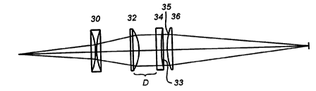
An apparatus of the present invention is also directed to shaping a laser
s beam emitted from a laser source to have a peak outer to average central
intensity ratio greater than or equal to 1.2. This apparatus is depicted in
Figures
3 and 4. It comprises a collimating optical element 32 positioned to collimate
a
laser beam emitted from a source. The invention further comprises a first
cylindrical optical element 34 having a first curved outer surface 33. The
first
i o cylindrical optical element is positioned to receive a collimated laser
beam from
the collimating optical element. The first cylindrical optical element is
spaced
0.1 mm to 5,000.0 millimeters from the collimating optical element. This
variable
spacing distance is denoted by the letter "D" in Figure 3.
The invention further comprises a second cylindrical optical element 36
15 having a second curved outer surface 35 that is oriented in a range of 89.5
degrees to 90.5 degrees out of rotational alignment with the first curved
surface.
The second cylindrical optical element is positioned to receive a laser beam
from the first cylindrical optical element. In a preferred embodiment, the
first and
second curved surfaces face each other.
a o As shown in Figures 3 and 4, a preferred embodiment of this invention
further comprises a biconcave lens 30 positioned between a laser beam
-10-
pMEN'DEO SHEET
CA 02338422 2001-O1-22~~~ ~ ~ ~ 1 5 4 2 1
/p~~~'~~S' ~ 1 4 FEB 2000
source and the collimating optical element, so as to project a more divergent
laser beam on said collimating optical element than would exist without the
biconcave lens.
In another preferred embodiment, the invention further comprises a laser
s source 71 capable of emitting laser light having a wave length of 1.06
microns
and further comprising a 600 micron diameter fiber 72 from which said laser
beam exits as shown in Figure 5. In a preferred embodiment, the laser beam
has a divergence angle of 4.4 degrees. In this preferred embodiment, the lens
may be constructed of fused silica glass and would further comprise an
1 o antireflection coating suitable for use with normal incidence radiation
having a
wave length of 1.06 microns.
In another preferred embodiment, the biconcave lens has a focal length
of 75 mm and is positioned 98 mm from the effective point source location of
the
laser beam. The collimating optical element is a spherical optical element
1 s having a focal length of 100 mm and located 41.3 mm from the biconcave
lens.
In a preferred embodiment, the first cylindrical optical element is a
cylindrical lens having a focal length of 200 mm, located 22 mm from the
collimating optical element. In a preferred embodiment, the second cylindrical
optical element is a cylindrical lens having a focal length of 152.4 mm and
a o located 5 mm from the first cylindrical optical element. The second
cylindrical
-11-
~M~h'~~l? SN~~i
CA 02338422 2001-O1-22
P~T/US 9 9 / 15 4 21
__ _ _
1 4 FED 2000
optical element is rotated 90 degrees around the axis of beam travel with
respect to the first cylindrical optical element and is oriented to have its
curved
surface facing the first cylindrical optical element as shown in Figure 5. In
a
preferred embodiment, the focal plane 73 at which the desired energy
s distribution is obtained is located 167.2 mm from the second cylindrical
optical
element.
The foregoing disclosure and description of the invention are illustrative
and explanatory. Various changes in the size, shape, and materials, as well as
in the details of the illustrative construction may be made without departing
from
1 o the spirit of the invention.
-12-
..
AMENflED SHEET