Note: Descriptions are shown in the official language in which they were submitted.
CA 02339010 2001-O1-30
WO 00/07048 PCT/US99/16615
LONG HAUL SINGLE MODE WAVEGUIDE
Background of the invention
The invention is directed to a single mode optical waveguide fiber
designed for long repeater spacing, high data rate telecommunication systems.
In particular, the single mode waveguide combines excellent bend resistance,
low attenuation, and large effective area, Aeff, features that are desired for
undersea applications.
A waveguide having large effective area reduces non-linear optical
effects, including self phase modulation, four wave mixing, cross phase
modulation, and non-linear scattering processes, all of which can cause
degradation of signals in high power systems. In general, a mathematical
description of these non-linear effects includes the ratio, P/Ae,r, where P is
optical power. For example, a non-linear optical effect can be described by an
equation containing a term, exp [P x Le,r/Ae"J, where Leh is effective length.
Thus, an increase in Ae~f produces a decrease in the non-linear contribution
to
the degradation of a light signal.
The requirement in the telecommunication industry for greater
information capacity over tong distances, without electronic signal
regeneration,
has led to a reevaluation of single mode fiber index profile design. The
genera
of these profile designs, which are called segmented core designs in this
application, are disclosed in detail in U. S. patent 4,715,679, Bhagavatula.
CA 02339010 2001-O1-30
WO 00/07048 PCT/I3S99/16615
2
The focus of this reevaluation has been to provide optical waveguides
which:
- reduce non-linear effects such as those noted above;
- are optimized for the tower attenuation operating wavelength range
around 1550 nm;
- are compatible with optical amplifiers; and,
- retain the desirable properties of optical waveguides such as high
strength, fatigue resistance, and bend resistance.
The definition of high power and long distance is meaningful only in the
context of a particular telecommunication system wherein a bit rate, a bit
error
rate, a multiplexing scheme, and perhaps optical amplifiers are specified.
There are additional factors, known to those skilled in the art, which have
impact upon the meaning of high power and long distance. However, for most
purposes, high power is an optical power greater than about 10 mw. In some
i 5 applications, signal power levels of 1 mW or less are still sensitive to
non-linear
effects, so that Aeff is still an important consideration in such lower power
systems.
A long distance is one in which the distance between electronic
regenerators can be in excess of 100 km. The regenerators are to be
distinguished from repeaters which make use of optical amplifiers. Repeater
spacing, especially in high data density systems, can be less than half the
regenerator spacing.
To provide a suitable waveguide for multiplexed transmission, the total
dispersion should be low, but not zero, and have a low slope over the window
of operating wavelength. In systems in which the suppression of potential
soliton formation is important, the total dispersion of the waveguide fiber
should
be negative, so that the linear dispersion cannot counteract the non-linear
self
phase modulation which occurs for high power signals.
A typical application for such a waveguide fiber is undersea systems
that, in order to be economically feasible, must carry high information rates
over long distances without regenerators and over an extended window of
wavelengths. The present invention describes a novel profile that is
singularly
CA 02339010 2001-O1-30
WO 00/07048 PCT/US99/16615
3
suited to for use in these stringent conditions. The desired 'properties of
the
waveguide fiber for such a system are set forth in detail below.
t~Afinitinnc
The following definitions are in accord with common usage in the art.
- The radii of the segments of the core are defined in terms of the index of
refraction. A particular segment has a first and a last refractive index
point.
The radius from the waveguide centerline to the location of this first
refractive
index point is the inner radius of the core region or segment. Likewise, the
radius from the waveguide centerline to the location of the last refractive
index
point is the outer radius of the core segment.
The segment radius may be conveniently defined in a number of ways,
as will be seen in the description of Figs. 1 & 2 below. In the case of Fig.
2,
from which Tables 1 & 2 are derived, the radii of the index profile segments
are
defined as follows, where the reference is to a chart of o % vs. waveguide
radius:
* the radius of the central core segment, r~, is measured from the axial
centerline of the waveguide to the intersection of the extrapolated central
index
profile with the x axis, i.e., the :~ % = 0 point;
* the outer radius, r2, of the first annular segment is measured from the
axial centerline of the waveguide to the intersection of the first annular
segment
profile with a vertical tine drawn through the 0 % point which is half of the
O
difference between the first and the second annular segment profile;
*the outer radius, r3, of the second annular segment is measured from
the axial centerline of the waveguide to the intersection of the second
annular
segment profile with a vertical line drawn through the 0 % point which is half
of
the 0 % difference between the second and third annular segment profile;
*the outer radius of any additional annular segments is measured
analogously to the outer radii of the first and second annular segments; and,
*the radius of the final annular segment is measured from the
waveguide centerline to the midpoint of the segment.
CA 02339010 2001-O1-30
WO 00/07048 PC1'/US99/16615
4
The width, w, of a segment is taken to be the distance between the inner
and outer radius of the segment. It is understood that the outer radius of a
segment corresponds to the inner radius of the next segment.
No particular significance is attached to a particular definition of index
profile geometry. Of course, in carrying out a model calculation the
definitions
must be used consistently as is done herein.
- The effective area is
Aeff = 2rr (JE2 r dr)2/(JE4 r dr), where the integration limits
are 0 to ~ , and E is the electric field associated with the propagated light.
The
effective area is wavelength dependent. The wavelength at which the effective
area is calculated is the wavelength at or near the center of the operating
window for which the waveguide fiber is designed. More than one Aett may be
assigned to a waveguide fiber which operates over a range of the order of
hundreds of nanometers.
- Effective diameter, De,f, may be defined as,
Aett = TT(Deff/2)2
- The relative index, 0%, is defined by the equation,
0% = 100 x (n~2 - nz2)/2n~2, where n~ is the maximum refractive index of
the index profile segment 1, and n2 is a reference refractive index which is
taken to be, in this application, the refractive index of the clad layer.
- The term refractive index profile or simply index profile is the relation
between
0 % or refractive index and radius over a selected portion of the core.
-The term a-profile refers to a refractive index profile expressed in terms of
~
(b) %, where b is radius, which follows the equation,
0(b)% _ ~(bo)(1 -[.b-bp~/(b,-bo)]°), where bo is the radial point at
which the
index is a maximum and b~ is the point at which 0(b)% is zero and b is in the
range b; < b < b, , where delta is defined above, b; is the initial point of
the a-
profile, b~ is the final point of the a-profile, and a is an exponent which is
a real
number.
Other index profiles include a step index, a trapezoidal index and a
rounded step index, in which the rounding is typically due to dopant diffusion
in
regions of rapid refractive index change.
CA 02339010 2001-O1-30
WO 00/07048 PCT/US99/16615
- Total dispersion is defined as the algebraic sum of waveguide dispersion and
material dispersion. Total dispersion is sometimes called chromatic dispersion
in the art. The units of total dispersion are ps/nm-km.
- The bend resistance of a waveguide fiber is expressed as induced
5 attenuation under prescribed test conditions. Standard test conditions
include
100 turns of waveguide fiber around a 75 mm diameter mandrel and 1 turn of
waveguide fiber around a 32 mm diameter mandrel. In each test condition the
bend induced attenuation, usually in units of dB/(unit length), is measured.
In
the present application, the bend test used is 5 turns of the waveguide fiber
around a 20 mm diameter mandrel, a more demanding test which is required
for the more severe operating environment of the present waveguide fiber.
Summary of the Invention
The novel single mode waveguide fiber of this application meets the
high performance telecommunication system requirements set forth herein.
A first aspect of the invention is a single mode optical waveguide fiber
having a segmented core of at least two segments, surrounded by a cladding
glass layer. The waveguide fiber has an effective area greater than 60 ~m2,
and preferably greater than 65 um2, over the wavelength range of about 1530
nm to 1570 nm, attenuation at 1550 nm less than 0.25 dB/km and preferably
less than 0.22 dB/km, a zero dispersion wavelength in the range of about 1565
nm to 1600 nm, a dispersion slope which provides a dispersion at 1560 nm
more negative than about -0.5 pslnm-km and a preferred 1560 dispersion
about -2 ps/nm-km. Typically the slope is in the range of about 0.10 to 0.14
ps/nm2-km. The total dispersion of the waveguide fiber is in the range of
about
-7.2 to -3.9 ps/nm-km at 1530 nm. The mode field diameter is in the range of
about 7.9 to 9.75 p.m over the 1530 nm to 1570 nm wavelength range.
These properties are achieved while maintaining good bend resistance,
i.e., an induced bend loss no greater than about 5 dB/m, for 5 turns about a
20
mm mandrel. Also, cut off wavelength of fiber in cabled form is held in the
range of about 1285 nm to 1500 nm. An added benefit is a polarization mode
dispersion less than about 0.076 ps/(km)'~2, and typically about 0.04
ps/(km)'~2
CA 02339010 2001-O1-30
WO 00/07048 PCT/US99/16615
6
The index profiles of the respective segments can be any of those
defined above, including an a-profile, a step index profile, or a trapezoidal
profile. Unless special steps are inserted in the process, the refractive
index
profiles will be rounded at points where the refractive index changes sharply.
The rounding is due to diffusion of the dopant materials used to change the
base glass refractive index. Thus any of these index profiles may be rounded
at particular points. For example, a step index profile, having a positive D%
will
typically have rounded upper and lower corners.
In one embodiment of the invention, the core segments all have a
positive 0 %. In another embodiment, the core comprises three segments, the
first being an a-profile, the second a step profile and the third a rounded
step
profile. Examples of this embodiment are set forth in Table 1 below.
In another embodiment of the invention, the core region comprises three
segments and the center has been compensated for dopant diffusion so that
the refractive index on or near the waveguide fiber centerline is not reduced
relative to the remainder of the center profile. An example of such centerline
compensation is shown in Fig. 3 wherethe dopant is germanium. The diffusion
compensated embodiment shows an average improvement in polarization
mode dispersion of about a factor of 5 relative to a comparable
uncompensated waveguide fiber profile. The polarization mode dispersion of
the novel waveguide fiber is less than 0.08 psl(km)'~2 and typically less than
about 0.04 ps/(km)'~2.
In a three segment embodiment, numbering the segments starting with
1 at the waveguide center, the segmented core is described by the parameters:
- o~ % in the range of about 0.75 to 1.25;
- r~ in the range of about 1.5 to 4.0 um;
- 02 % in the range of about 0.00 to 0.15 %;
- 03 % in the range of about 0.2 ~0 0.7;
- mid point radius rs in the range of about 4 to 8 ~.m; and,
width of the third segment in the range of about 0.5 to 3 Vim.
A preferred range is:
CA 02339010 2001-O1-30
WO 00/07048 PCT/US99/16615
7
- 0~ % in the range of about 0.85 to 1.20;
- r~ in the range of about 2.0 to 3.5 pm;
- 02 % in the range of about 0.00 to 0.08 %;
- 03 % in the range of about 0.3 to 0.7;
- mid point radius r3 in the range of about 5 to 7.5 Vim; and,
width of the third segment in the range of about 0.8 to 2.0 p.m.
A more preferred embodiment is:
- 0~ % in the range of about 0.95 to 1.15;
- r, in the range of about 2.5 to 3.0 pm;
- 02 % in the range of about 0.00 to 0.04 %;
- 03 % in the range of about 0.3 to 0.7;
- mid point radius r3 in the range of about 5 to 7.5 p.m; and,
- width of the third segment in the range of about 0.8 to 1.5 Vim.
In another embodiment the total dispersion at 1560 nm is more negative
than about -1 ps/nm-km.
In yet another embodiment, centerline diffusion is either uncompensated
or partially compensated so that there is an indentation of refractive index
on
centerline having a minimum D% of no more than about 0.20 of O,%. The
indentation is typically of the shape of an inverted cone, i.e., the apex of
the
cone points downward, and the radius at the widest part of the cone is no
greater than about 0.4 p.m.
Brief Description of the Drawings
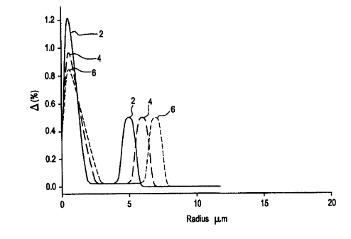
Figs. 1 a & b are charts of 0 % vs. radius each illustrating a modeled index
profile similar to that of the invention.
Fig. 2 is a 0 % vs. radius chart showing the definitions of radius and width
used
in this application.
Fig. 3 is a chart of ~ % vs. radius showing an embodiment of the invention.
CA 02339010 2001-O1-30
WO 00/07048 PCT/US99/16615
8
Detailed Description of the Invention
The novel single mode optical waveguide is characterized by its
segmented core design that provides the unusual combination of properties set
forth above. These properties are achieved by selecting a proper refractive
index profile shape of each of the segments and selecting the appropriate
relative refractive index delta, D; %, and radial extent, r;, of the segments.
The
profile parameters are known to interact. For example, a center region a-
profile having an a of about 1, will have a radius different from a center
region
having a trapezoidal index to provide fibers having essentially identical
properties.
The definitions of radius used herein are shown in Fig. 2. The radius of
the central segment is shown by line r, drawn from the core centerline to the
intersection of extrapolated line 14 with the horizontal axis. The outer
radius of
segment is line r2 drawn from the centerline to the vertical line descending
from
the point 18 which marks the point where the relative index is half the
difference between Q2%, the relative index of segment 16, and 03%, the
relative index of segment 20. The radius r3 of the final annular segment 20 is
draw to the center point 26 of that segment. The geometry is fully specified
when the width w of the final segment is selected. This width is shown as fine
w that lies between points 18 and 22, the respective points of half index
differences between segments 16 and 20, and segment 20 and clad 24. The
radius of the centerline indentation is shown as line 30 drawn horizontally
from
the centerline at the widest point of the inverted cone indentation.
Three computer generated profiles, 2, 4, and 6, are shown in Fig. 1 a.
The center segments and the associated outer annular segments have
corresponding numbers for purposes of clarity. Each profile has an inverted
cone indentation on centerline. Given the overall shape of the segmented core
index profile, the properties of a waveguide fiber having that segmented core
shape may be calculated. In the case of Fig. 1 a, profile 4 provides the
desired
fiber characteristics. Fig. 1 b shows three additional segmented core
profiles, 8,
10, and 12. In this illustration, profile 10 yields the desired fiber
properties.
CA 02339010 2001-O1-30
WO 00/07048 PCT/US99/16615
9
The profile shown in Fig. 3 is a measured profile of a waveguide fiber
having a refractive index profile in accord with the invention. Table 1 gives
the
core index profile parameters for this embodiment. The centerline diffusion is
compensated in this design.
Table 1.
Actual Profile
0~ % 1.15
D % on centerline0
02 % 0.05
D3 % 0.5
r~ ~.m 2.5
r2 pm 5.5
w um (outermost 1
annular segment)
The average property values of a large number of waveguide fibers
made using the parameters of Table 1 as target were:
- attenuation at 1550 nm - 0.204 dB/km;
- mode field diameter - 9.29 Vim;
- effective area at 1550 nm- 70.9 p.m2;
- zero dispersion wavelength - 1576 nm;
- total dispersion at 1530 nm - (-5.565 ps/nm-km);
- total dispersion at 1560 nm - (-1.892 ps/nm-km);
- cut off wavelength - 1429.6 nm in cabled form; and,
- polarization mode dispersion - 0.037 ps/(km)'~2.
Thus the manufacturing results provide a waveguide fiber suitable in every
respect for use in severe environments such as undersea telecommunications
cables. The manufacturing results also serve to validate the computer model.
CA 02339010 2001-O1-30
WO 00/07048 PCT/US99I16615
Although particular embodiments of the invention have been herein
disclosed and described, the invention is nonetheless limited only by the
following claims.