Note: Descriptions are shown in the official language in which they were submitted.
CA 02339024 2001-O1-29
WO 00/06393 PCT/US99/17427
PRINTING SLEEVES AND METHODS FOR PRODUCING SAME
Background of the Invention
This invention relates to printing sleeves which are readily mountable onto
and dismountable from printing cylinders, more particularly to printing
sleeves
which are expandably mountable and dismountable employing a pressurized gas,
and to methods for producing such printing sleeves.
In past printing operations, flexible printing plates were mounted onto the
outer surface of a printing cylinder. These printing plates were used for
printing
of ink images onto a printing medium. Typically, the back of the printing
plates
were adhered directly to the printing cylinder. Since these plates were not
readily
interchangeable from one cylinder to another, the use of a multiplicity of
printing
cylinders to perform a multiplicity of jobs was required. This presented
severe
storage and cost problems to the end user.
Therefore, in an effort to overcome this problem, printing sleeves were
developed which were mountable onto and dismountable from the printing
cylinders. Compressed gas, generally compressed air, passing in a
substantially
radial direction from holes located within the printing cylinders, was used to
expand the sleeve to a limited extent for facilitating the mounting and
dismounting
operations.
This latter mode of mounting and dismounting of a printing sleeve is
described in U.S. 3,146,709. In that patent, a "wound" printing sleeve, i.e.,
a
helically wound paper sleeve, is fitted onto a hollow printing sleeve. The
printing
sleeve is used as a carrier roll for rubber printing plates attached thereto.
Air
25 pressure is radially applied through the holes in the external surface of
the printing
cylinder for limited radial expansion of the sleeve. The sleeve is then
axially
mounted onto the printing cylinder by moving the cylinder to an upright
position
and filling the internal chamber of the cylinder with compressed air.
As the sleeve is moved over the upper end of the cylinder, the exiting air
30 expands the sleeve and forms a lubricating air film between the inner
sleeve and
the outer cylinder. This air film permits axial mounting of the sleeve to a
position
CA 02339024 2001-O1-29
WO 00/06393 PCTNS99/17427
about the cylinder. When the sleeve was in such a position, the airflow is
terminated, and the sleeve is contracted forming an interference fit about the
print
cylinder.
However, difficulty has been encountered when wound sleeves are
employed since expansion does not effectively take place unless high-pressure
air,
substantially higher than the 50-100 psi air generally available in production
facilities, is radially conveyed between the sleeve and the printing cylinder
to
facilitate the mounting and dismounting operation. This expandability problem
occurs because of the thickness of the sleeve walls and the nature of the
materials
of construction. If pressures above the available air pressure at the
production
facility are required to expand the sleeve, auxiliary sources of compressed
air must
be purchased. For example, in printing operations where sleeve thicknesses of
about 0.01 S" or greater are required, such as in the modern flexographic
printing
industry, wound sleeves cannot readily be employed because they do not undergo
the requisite expansion using available production compressed air.
Furthermore,
these wound sleeves cannot be effectively used because of the leakage problems
inherent in their design, which in this case, U.S. 3,146,709, comprises a
polyester
film held in position by helically-wound paper tape. This type of construction
forms a leakage path for the air and reduces the effectiveness of the
lubricating
fluid.
In order to overcome the problems inherent in the U.S. 3,146,709 wound
printing sleeve, U.S. 3,978,254 provides for a mechanically adhered wound
printing sleeve in which three layers of adhesive tape are helically wound
about a
mandrel to form a carrier sleeve, with two of the helixes being wound at the
same
angle and the remaining helix being wound at a different angle.
The convolution of the helixes is said to impart some degree of strength,
rigidity and leakage protection to the printing sleeve. Neither of the
printing
sleeves of U.S. 3,146,709 or U.S. 3,978,254 is unitary in construction, but is
2
CA 02339024 2001-O1-29
WO 00/06393 PCTNS99/17427
instead fabricated of a composite of wound materials. The outer surface of the
U.S. 3,978,254 wound sleeve also has a plurality of surface irregularities
formed
therein and is therefore not "round" to the extent required by the
flexographic
printing industry. These carrier sleeves are made of a flexible, thin tape
material
5 which provides a minimum of structural integrity, which exhibit minimal
strength
and durability properties. Moreover, as the printing plates are adhered to the
printing sleeve they are moved from one position to another as they are
aligned on
the plate surface. In order to trim excess material from the plate from the
sleeve
surface, they must be cut with a sharp instrument such as a knife. The
synthetic
10 plastic tape used to form the above-described sleeve cannot withstand even
the
minor cutting action required in positioning of the printing plates.
Another type of printing sleeve is one which is made of a metallic material.
As in the case of wound sleeves, metallic sleeves are not readily expandable
and
therefore must have a wall thickness which is be quite thin, i.e., thicknesses
of up
15 to only about 0.005", in order to be capable of undergoing the limited
expansion
required of printing sleeves. As indicated above, this minimum thickness level
required of metallic sleeves is a problem in applications such as modern
flexographic printing and the like. Moreover, printing metallic sleeves are
not
durable and are readily damaged. For instance, they can easily form kinks in
their
20 outer surface when they are stored without being supported by a printing
cylinder.
Dimensional stability is a problem in printing applications requiring that
the outer surface of a printing sleeve structure have a true cylindrical
shape. In
some cases, this true cylindrical shape must even be within a 0.001 "-0.0025"
tolerance level in order to be acceptable in, for example, uses such as in the
25 process printing industry. The outer printing surface in these applications
must
accurately conform to a uniformly constant, cylindrical outer shape in order
to
accurately imprint a print image onto a printing medium. Many of the prior art
printing sleeves do not meet these requisite tolerance levels.
CA 02339024 2001-O1-29
WO 00/06393 PCT/US99/17427
U.S. 4,144,812 and U.S. 4,144,813 provide non-cylindrical printing
sleeves and associated air-assisted printing rolls designed in a tapered or
stepped-
transition configuration, the change in the sleeve or printing cylinder
diameter
from one end to the other being progressive, i.e., increasing or decreasing
according to the direction one is moving along the printing sleeve or roll.
The
printing roll comprises an outer surface having one end of a diameter greater
than
the other longitudinal end. The printing sleeve has an inner surface designed
to
form an interference fit with the outer surface of the printing roll only at
the
designated working position, and not along the entire axial uniform cross-
sectional
extent of the tapered sleeve.
This non-cylindrical sleeve is fabricated of a highly rigid material having a
low degree of expandability. These sleeves have a thickness of at least about
0.01 S". An extremely high air pressure, in excess of 125 psi, and typically
about
250 psi or higher, is thus required to be introduced as the sleeve is being
fitted
onto the underlying air-assisted, printing roll in order to extend the radial
dimension of the printing sleeve to a position capable of achieving complete
coverage of the printing cylinder by the sleeve. Complete coverage is required
in
this system to achieve a proper interference fit. Since a pressure in excess
of 125
psi is required herein, the system must satisfy various governmental
regulations
relating to pressure-rated containers. Conventional cylindrically-shaped, air-
assisted printing presently on hand cannot readily be retrofitted to
accommodate
this non-cylindrical configuration because they cannot meet the above-
described
pressure-rating requirement. Therefore, they must be replaced, at great cost,
by
new non-cylindrical printing cylinders capable of meeting these government
regulations.
U.S. 4,119,032, describes an air-assisted printing cylinder mounted in a
printing machine in such a way that a printing sleeve on its outer surface can
be
removed axially while the roll remains substantially in its working position.
One
4
CA 02339024 2004-07-21
end bearing of the printing cylinder is removably secured to a side of the
machine
frame. For axial positioning, an adjustable restrainer engages the roll axle
at that
end. Beyond the other side frame a counterpoise acts on the printing cylinder
axle
to support the printing cylinder when one end bearing is removed.
In U.S. 4,089,265, a flexographic printing roll is provided comprising a
rigid base tube having perforations in the form of a plurality of small
apertures and
a printing sleeve on the tube strained to grip the tube to retain the sleeve
securely
on the tube. There is no underlying printing cylinder in the conventional
sense in
this system.
In order to overcome the aforementioned problems, a cylindrically shaped
printing sleeve was produced according to the teachings of U.S. 4,903,597 ("US
'597"). US '597 has been assigned to the assignee of the present patent
app 1 ication.
The US '597 printing sleeve is unitary, substantially airtight, and can be
frictionally mounted onto a conventionai cylindrically shaped printing
cylinders
having a complementary cylindrical outside diameter. The US '597 sleeve can
also
be readily expandable using a low-pressure fluid and has a true outer wall
surface
capable of being used in modern flexographic printing applications.
The US '597 printing sleeves are typically fabricated of a polymeric
material, and preferably comprise a reinforced, non-permeable laminate
structure
including at least one reinforcing internal layer of a woven fabric of
synthetic
fibers or organic fibers. Another internal layer may also be included which is
non-
permeable and is typically formed of synthetic fibers. Preferably, the
synthetic and
organic fibers are of high strength, and the reinforced non-permeable internal
layers comprise a non-woven fabric of synthetic fibers.
The US '597 printing sleeve has been the state of the art product since the
late 1980's. The presence of the US '597 sleeve in the marketplace has caused
the
overall printing sleeve business to grow significantly. This has lead others
to
CA 02339024 2001-O1-29
WO 00/06393 PCT/US99/17427
develop alternative printing sleeves and printing sleeve manufacturing
methods.
For example, Dupont has developed a flexible Mylar printing sleeve system.
SUMMARY OF THE INVENTION
5 It has been recognized by applicants, in view of their experience in the
print sleeve business, that although the US '597 printing sleeves remains
intact as
the industry standard, increased competition and higher costs of manufacture
are
now a commercial reality. Certain printing sleeves which have been developed
in
the last several years can exhibit certain physical properties which are even
better
10 than the US '597 printing sleeves. The aforementioned Mylar sleeves, for
instance, have a higher affinity for having printing tapes (used in printing
operations) adhered thereto. Also, the US '597 printing sleeves are presently
being
hand-built because the manufacturing operation is extremely difficult to
automate.
Therefore, producing the US '597 printing sleeves is very labor intensive.
This
15 can result in a relatively high manfacturing reject rate. Since material
costs
continue to rise, the overall manufacturing expense for the US '597 sleeves is
relatively high as compared to new domestic and foreign companies who have
entered the printing sleeve marketplace in the past several years.
There are also certain technical issues which have arisen regarding the US
20 '597 printing sleeves, as follows:
1. They are not as easily mountable as compared to certain competitive
sleeves.
2. They lack surface adhesion advantages present in certain
competitive sleeves.
25 3. They do not withstand certain high temperature applications required
for the vulcanization of polymeric coverings now used in lazer
engraving plate technology.
6
CA 02339024 2001-O1-29
WO 00/06393 PCT/US99/17427
4. They do not have the durability that certain end users in the sleeve
market demand.
Therefore, in an effort to supplement the present product Line of US '597
printing sleeves, a new printing sleeve product and new method of
manufacturing
that new product have been devised. The new method of this invention comprises
spraying of a novel polymeric composition as opposed to the process of US
'597,
namely, the formation of a laminate printing sleeve structure. No spray
technology is available for spraying polymeric materials that have the desired
properties to produce flexographic printing sleeves having the requisite
physical
and chemical properties. More specifically, no conventional material, either
polymeric or otherwise, meets all of the product specifications for
effectively and
efficiently manufacturing high quality flexographic printing sleeves.
The subject printing sleeve comprises a combination of chemistries to
produce a sleeve having both high temperature resistance and a high level of
flexibility and machinability. The gel characteristics of the subject
polymeric
materials have been modified to achieve an extreme high-speed gel for
sprayability. For example, the preferred polymer system of the invention
herein
employs a polyurea for high temperature resistance and a polyurethane for high
flexiblity and machinability. The preferred polymeric material is the SE-271
spray composition manufactured by Burtin Corporation of Santa Ana, CA.
The printing sleeve of the present invention is formed of a substantially
unitary construction unlike unlike prior art flexographic sleeves, such the US
'597
sleeve, which are made of structural laminates. In fact, the printing sleeve
of this
invention comprises a non-laminate construction. Moreover, unlike prior art
printing sleeves which require auxiliary structural reinforcing materials to
impart
structural integrity thereto, the flexographic printing sleeve of this
invention
includes no auxiliary structural reinforcing materials. This also results in
better
tape adhesion for mounting of printing indicia on the sleeve than in the case
of US
7
CA 02339024 2001-O1-29
WO 00/06393 PCT/US99/17427
'597. Because the new technology of this invention is made substantially
solely
of polymeric materials, when it is machined, there is a very smooth uniform
outer
surface which is produced. Contrarily, when the sleeve of US '597 is machined,
it
has microscopic fiber ends on the outer sleeve surface which interfere with,
and
5 limit, the adhesion of the common mounting tapes which are used in the
application of printing indicia thereto.
The present invention is directed to a flexographic printing sleeve formed
of a sprayed, cured polymeric material. In the preferred construction, the
flexographic printing sleeve of the invention is formed of a plurality of
layers of
10 the curable polymeric material, which fuse together to produce a sleeve
having a
self supporting substantially unitary construction.
This new type of flexographic printing sleeve is typically resistant to
damage and distortion to its structural integrity at high processing
temperatures.
More specifically, this printing sleeve is damage and distortion resistant at
a
15 temperature of about 250 degree F., preferably at a temperature of about
275
degree F., and more preferably at a temperature of about 300 degree F.
Although the flexographic printing sleeve of this invention is produced by
spray applications, and is not formed of a structural laminate construction,
it
nevertheless maintains distinguishing chemical and physical properties. For
20 instance, it has a relatively low shrink rate (0.035% inhibited by tool), a
high
flexibility (10% elongation), and high strength and hardness (Durometer of 70
on
the Shore "D" scale). The subject sleeve is also extremely durable and
fracture
resistant for long life. It also exhibits low porosity for good surface finish
and has
sufficient flexibility to be mounted easily on conventional print cylinders
using
25 low pressure air. It is also has sufficient strength and stiffness to not
slip on the
print cylinder under conventional flexographic printing conditions.
The printing sleeve of this invention exhibits a high level of environment
compatibility since it contains no voc components or hazardous by products.
8
CA 02339024 2001-O1-29
WO 00/06393 PCT/US99/17427
Stated another way, the curable polymeric material employed in forming the
subject printing sleeve typically comprises a non-solvent-containing sprayable
curable polymeric material. Thus, no EPA permits are required to be maintained
at the manufacturing site.
More specifically, the printing sleeve is preferably formed of a polymeric
material which comprises a polyurethane-polyurea material. The material is
preferably a blend of highly catalyzed polyurea and polyurethane sprayable at
high
temperature and high pressure to produce the flexographic printing described
herein.
The flexographic printing sleeve is readily axially mountable onto and
dismountable from a complementary shaped printing cylinder. The cross-
sectional inner and outer diameter of the flexographic printing sleeve is
expandable by introducing a relatively low pressure fluid between the inner
surface of the printing body sleeve and the outer cylindrically-shaped wall of
the
15 printing cylinder. The sleeve is contractible from its expanded position by
releasing the low pressure fluid. Typically, the subject method utilizes less
than
100 psi fluid pressure to mount and dismount the flexographic printing sleeve
of
this invention.
The subject flexographic printing sleeve preferably comprises inner and
20 outer cylindrically-shaped walls of substantially constant cross-sectional
inner and
outer diameter.
The printing sleeve of this invention has a wall thickness which is typically
up to about 0.50", preferably up to about 0.45", and more preferably up to
about
0.40", and most preferably up to about 0.35". By employing the method of the
25 present invention, the subject flexographic printing sleeve can be formed
in a
manner wherein the average time for producing the sleeve is preferably not
more
than about 1.0 hour, more preferably not more than about 0.75 hour, and most
preferably not more than about 0.5 hour. Stated another way, the method of
this
9
CA 02339024 2004-07-21
invention can form a non-laminated, substantially airtight, seamless,
flexographic
printing sleeve built with in a single spray application process that can be
completed
in a much shorter time period than presently commercially feasible in the
marketplace.
In accordance with one aspect of the present invention, there is provided a
method for producing a flexographic printing sleeve which is readily axially
mountable on and dismountable from a complementary shaped printing cylinder,
which comprises: providing an apparatus for receiving a sprayed curable
polymeric
material and for forming said flexographic printing sleeve; spraying said
curable
polymeric material directly onto said apparatus; and curing said polymeric
material
and forming a flexographic printing sleeve, removing said printing sleeve from
said
apparatus, for mounting said sleeve onto said printing cylinder, said sleeve
having a
substantially unitary construction which is self supporting, a cross-sectional
inner and
outer diameter of the flexographic printing sleeve being expandable by
introducing a
relatively low pressure fluid between an inner surface of the flexographic
printing
sleeve and an outer cylindrically-shaped wall of the printing cylinder, the
flexographic
printing sleeve being contractible from its expanded position by releasing
said low
pressure.fluid, said flexographic printing sleeve having a structural
integrity which is
resistant to substantial damage or distortion.
In accordance with another aspect of the present invention there is provided a
method for producing a cylindrically-shaped flexographic printing sleeve, the
flexographic printing sleeve being readily axially mountable on and
dismountable
from a complementary printing cylinder, which comprises: providing an
apparatus for
receiving a curable polymeric material and for forming said flexographic
printing
sleeve; spraying said curable polymeric material directly onto said apparatus;
curing
said curable polymeric material and forming a cured printing sleeve blank; and
forming said flexographic printing sleeve from said cured printing sleeve
blank,
removing said printing sleeve from said apparatus, for mounting said sleeve
onto said
printing cylinder, said flexographic printing sleeve having a substantially
unitary
construction which is self supporting, a cross-sectional inner and outer
diameter of the
flexographic printing sleeve being expandable by introducing a low pressure
fluid
between an inner surface of the flexographic printing sleeve and an outer wall
of the
CA 02339024 2004-07-21
printing cylinder, the flexographic printing sleeve being contractible from
its
expanded position by releasing said low pressure fluid, and the flexographic
printing
sleeve having a structural integrity which is resistant to substantial damage
or
distortion.
In accordance with yet another aspect of the present invention, there is
provided a method for producing a flexographic printing sleeve which is
readily
axially mountable on and dismountable from a complementary shaped printing
cylinder, which comprises: providing an apparatus for receiving a sprayed
curable
polymeric material and for forming said flexographic printing sleeve; spraying
said
curable polymeric material directly onto said apparatus; and curing said
polymeric
material and forming a flexographic printing sleeve, removing said printing
sleeve
from said apparatus, for mounting said sleeve onto said printing cylinder,
said sleeve
having a substantially unitary construction which is self supporting, a cross-
sectional
inner and outer diameter of the flexographic printing sleeve being expandable
by
introducing a relatively low pressure fluid between an inner surface of the
flexographic printing sleeve and an outer cylindrically-shaped wall of the
printing
cylinder, the flexographic printing sleeve being contractible from its
expanded
position by releasing said low pressure fluid, the flexographic printing
sleeve having a
structural integrity which is resistant to substantial damage or distortion,
and an
average time for producing the flexographic printing sleeve being not more
than about
1.0 hour.
In accordance with still yet another aspect of the present invention, there is
provided a method for producing a cylindrically-shaped flexographic printing
sleeve,
the flexographic printing sleeve being readily axially mountable on and
dismountable
from a complementary printing cylinder, which comprises: providing an
apparatus for
receiving a curable polymeric material and for forming said flexographic
printing
sleeve; spraying said curable polymeric material directly onto said apparatus;
curing
said curable polymeric material and forming a cured printing sleeve blank; and
forming said flexographic printing sleeve from said cured printing sleeve
blank,
removing said printing sleeve from said apparatus, for mounting said sleeve
onto said
printing cylinder, said flexographic printing sleeve having a substantially
unitary
construction which is self supporting, a cross-sectional inner and outer
diameter of the
l0a
CA 02339024 2004-07-21
flexographic printing sleeve being expandable by introducing a low pressure
fluid
between an inner surface of the printing body sleeve and an outer wall of the
printing
cylinder, the flexographic printing sleeve being contractible from its
expanded
position by releasing said low pressure fluid, the flexographic printing
sleeve having a
structural integrity which is resistant to substantial damage or distortion,
and an
average time for producing the flexographic printing sleeve being not more
than about
1.0 hour.
BRIEF DESCRIPTION OF THE DRAWINGS
FIG. 1 is a pictorial view of an exemplary printing sleeve manufacturing
system of the present invention.
FIG. 2 is a perspective view of a flexographic printing sleeve of the present
invention produced by the subject method such as by employing the system
depicted
in FIG 1.
1 S FIG. 3 is an enlarged, sectional view of the printing sleeve of FIG. 2 in
use as
mounted on a conventional printing cylinder.
DETAILED DESCRIPTION OF THE PREFERRED EMBODIMENT
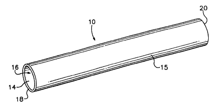
The flexographic printing sleeve 10 shown in FIGS. 2 and 3 can be produced
by the printing sleeve manufacturing system, denoted generally as "100", which
is
depicted in FIG. 1. System 100 includes certain tools used in the formation of
a
printing sleeve blank (not shown), which in turn is formed into a flexographic
printing
sleeve 10. For example, metal mandrel 112 is used as the form onto which the
polymeric material is directly sprayed. This direct spraying operation is
conducted
without-the use of any intermediate materials or steps. This technique is
highly
accurate and the mandrel 112 diameters are exceptionally true. More
specifically, the
outer diameter of mandrel 112 exhibits a total indicated runout and
circularity
tolerance which is preferably within .0015", more preferably within .0010",
and most
preferably within .0005". They are drilled to be air chambers, and air
pressure is used
to float the sleeve 10 off of the mandrel 112 after it is sprayed. The nominal
outer
diameter of the mandrel 112 is precisely
lOb
CA 02339024 2001-O1-29
WO 00/06393 PCT/US99/17427
oversized to compensate for shrink rates of the spray material. These tools
are
various diameters and lengths to accommodate the printing industry needs.
A spray station 114 maintains the mandrel 112 in a horizontally-extending
position, and rotates mandrel 112 at a predetermined speed to match the
application rate for a given sleeve size. An exemplary spray system 122, for
spraying a curable polymeric material 115 onto the mandrel 112, is a Graco
Foam
Cat System Model No. 973-005. The spray system 122 has a spray head 126. The
orifice of the nozzles in spray system 126 have a :Ol 1" diameter. Air is
supplied to
the spray head 126 through an air dryer 134 that has a dew point of -40
degrees F.
The spray head 126 is held in a traversely-movable apparatus 136 that
resembles a lathe feed assembly. Spray head 126 traverses along the axis of
the
spray station 114 on horizontally-extending rods 117, 119 at a predetermined
rate
for properly depositing spray material in layers onto mandrel 112 so that
printing
sleeve 10 will have a substantially unitary construction which is self
supporting.
The speed of the rotating mandrel 112 is controlled by a computer system (not
shown), which is D.C. motor driven by belt and pulley assembly 130.
The operation of the apparatus 136 is also controlled by a second D.C.
motor driven by belt and pulley assembly 132. Assembly 132 is employed to
facilitate control of the thickness of each layer of polymeric spray material
115,
and the final thickness of the layers of polymeric spray material 11 S which
is
actually applied to mandrel 112. A self contained exhaust system 140 is used
to
remove all oversprayed polymeric material 115, and to keep the spray particles
from being deposited onto the part.
The chemicals are a basic "A" and "B" combination which are contained
in vessels 116, 118. The chemical A and B are supplied to the sprayer unit
with
Graco transfer pumps 120. Chemical A is typically a material such as a Burtin
SE-271 isocyanate pre-polymer resin, and chemical B is typically a material
such
as a Burtin SE-271 polyol pre-polymer resin.
11
CA 02339024 2001-O1-29
WO 00/06393 PCT/US99/17427
Certain process variables were identified and controlled in order to achieve
the desired result. First, is the temperature. More particularly, the initial
temperature of the mandrel 112, the temperature of the chemicals introduced
into
the spray head I26, and the temperature at which the sleeve is removed from
the '
mandre1112.
Second, are the spray head speeds and feed rates, particularly the
following: the distance and angle of spray head 126 to the mandrel 112, the
traverse rate of movement of the spray head 126 along axis 114, and the
rotational
speed of mandrel 112 during application of the spray material 115. Layer
control
of applied material 115 is controlled by an algorithm in a computer control
system
(not shown) which uses tool speed, feed rate and deposit rate of the spray
material
115 as the process control variables.
The third variable is spray pressures and orifice sizing, particularly the
following: the pressure of chemicals to the spray head (1500psi) and the
sizing of
the orifice in spray head (.0l 1 ").
The fourth variable is demount and cure times, particularly the following:
demount (demold) at proper time and temperature to achieve more exact diameter
sizing. , Due to high exotherm temperatures during spraying, no post cure is
required.
The fifth variable is tool sizing, particularly the following: mandrel OD is
001" PER 1.00" dia. larger than finished inside diameter of the sleeve.
More specifically, in use, mandrel 112 is prepared with a mold release
agent and bolt on collars for fitting into the spray station 114. The mandrel
112 is
then placed into spray station 114 which is then brought up to a spray
temperature,
preferably about 110 to 120 degrees F. Chemicals A and B in vessels 116 and
118
are pre-mixed and preheated to the requisite spray process temperatures.
Preferably, pumps 120 are brought to pressures of about 1350 to 1500 psi, and
fluid lines 124 are preheated to the above-described spray temperature. The
12
CA 02339024 2004-07-21
rotational speed of mandrel 112 is then adjusted to between about 15 to 25
rpm, and
operation of the spray head 126 is begun, the transverse movement of the spray
head
126 being selected depending on the dimensions of the specific print sleeve
blank
being produced.
The spraying operation begins and several pressure and temperature sensors
(not shown) monitor the process to insure that consistent thickness layers of
the spray
115 will be deposited onto mandrel 112. The final thickness of the spray is
typically
up to about 0.500", with each layer preferably being about .010" in thickness.
As the printing sleeve blank builds in thickness on the mandrel 112, the
exotherm of the material builds the temperature of the blank until the curing
process is
complete. Typically, temperature of about. 250 degrees F. are reached during
the
curing process.
Mandrel 112 is removed from the station 114 by introducing air into the
mandrel to float the part off of the mandrel. The mandrel then is cooled to
ambient
temperature and is made ready for the next sleeve blank to be manufactured.
The printing sleeve blanks (not shown) are then remounted onto a separate,
properly-sized mandrel for final machining in a standard lathe to produce the
flexographic printing sleeve. Round ceramic inserts are used for the finish
cut. After
final finishing and quality control checking the flexographic printing sleeve
is ready
to ship.
Referring now to FIGS. 2 and 3, in use, a cylindrically-shaped printing sleeve
10 is provided which comprises cylindrically-shaped inner and outer walls 14
and 1 S
which define a hollow inner chamber 16, and a pair of end sections 18 and 20.
Sleeve
10 is depicted mounted on an illustrative conventional printing cylinder 22,
such as
described in U.S. Pat. No. 4,903,597.
13
CA 02339024 2001-O1-29
WO 00/06393 PCT/US99/17427
Typically, sleeve 10 will serve as a support for the application of printing
indicia (not shown), preferably flexographic printing plates, which are
generally
made of a flexible polymeric material. Any suitable indicia for printing onto
a
printing medium may be set on these printing plates. Alternatively, outer wall
15
may itself be employed as the means for printing onto a printing medium.
Various
methods can be employed to engrave the outer wall 15. For example, one could
employ chemical or photochemical engraving techniques to form the requisite
means for producing the print indicia.
The printing sleeve 10 and the printing cylinder 22 are cylindrical and have
a constant diameter. The outer wall 23 of the cylinder 22 has a slightly
larger
diameter than the inner wall 14 so that the sleeve will firmly frictionally
fit onto
the cylinder. The cylinder 22 is hollow and has a cylindrical chamber 25 which
is
used as a compressed air chamber. The cylinder 22 comprises a cylindrical tube
26
fitted with airtight endplates 28 and 29. A plurality of spaced-apart,
radially-
exterc?ing apertures 30 are provided in the tube 26 through which air from the
chamber 25 may pass for expanding the sleeve 10 during mounting and
dismounting operations.
Air is introduced into the chamber 25 through air hose 34. Trunnions 31
and 32 are provided for rotationally supporting cylinder 22. A coupling
element
33 is disposed within endplate 29 and provides a means for connecting air hose
32
to cylinder 22 for introducing compressed air to the cylinder chamber 25.
14