Note: Descriptions are shown in the official language in which they were submitted.
CA 02339135 2001-O1-30
-- WO 00/06247 PCT/US99/17304
-1-
SLOTTED PACINO/SHOCRINQ ELECTRODE
BACR(3ROUND OF THE INVENTION
I. Field of the Invention
This invention relates to leads used in conjunction
with cardiac rhythm management devices. More
particularly, the present invention relates to the
surface electrodes for such leads and a technique for
reducing the length of such electrodes while at the same
time providing an effective bond between the electrode
and adjoining electrically insulative material.
II. Description of the Prior Art
Over the past thirty years, a variety of leads have
been developed for use in conjunction with either an
implantable heart pacemaker or implantable heart
defibrillator. Such leads typically include one or more
elongated conductors surrounded by an insulative body,
and one or more electrodes coupled to the conductors.
The conductors and electrodes provide an electrical path
for signals from the heart and delivery of pulses to the
heart.
Over the years, a variety of leads have been
developed which include one or more ring electrodes.
Most often, the ring electrode is a metal band which
surrounds the insulative body of the lead. An orifice in
the lead body beneath the ring electrode allows the ring
electrode to be coupled to a conductor within the lead
body.
Recently, "over the wire" leads have been developed.
These leads have been given this name because they are
implanted by sliding them over a guidewire. In addition
to the conductor, insulative body and electrode, these
leads have a central lumen which permits the lead to be
passed over the guidewire.
More recently, there has been a need to create leads
having smaller cross-sectional diameters. This is true,
for example, of leads designed to apply stimulating
pulses to the left ventricle without residing in the left
CA 02339135 2001-O1-30
-- . WO 00/06247 PGT/US99/17304
_2_
ventricle. To be successfully implanted, such leads must
pass through the superior vena cava, the right atrium,
and the coronary sinus into the great vein of the heart
so that the electrode resides in a branch of the coronary
vein. This is a tricky path which is best navigated by
first using a guidewire and then sliding the lead over
the guidewire.
Traditional ring electrodes tend to be relatively
long and inflexable. To improve the overall flexability
of the lead and thus make it easier to steer, there is a
need to reduce the overall length of the electrode. This
must be done, however, in a fashion that does not weaken
the joints which exists on the proximal and distal ends
of the electrode between the edges of the electrode and
the electrically insulative body of the lead.
Larger diameter leads have proven to be strong and
durable. However, as the diameter is reduced strength
can be lost. This is particularly true when ring
electrodes are used and joints are formed between the
ring electrode and in the insulative body. The joints
cause potential weak spots in the lead. Thus, there is a
real need to eliminate these weak spots or at least
increase the strength of the lead at the interface
between the insulative body and the ring electrode. More
specifically, there is a real need for a lead having an
interface between a ring electrode and insulative body
strong enough to handle any axial loading which may be
imparted during insertion or removal of the lead.
SUMMARY OF' THE INVENTION
The present invention is intended to eliminate
potential weak spots at the interface of the insulative
body and ring electrode. Specifically, the present
invention includes a ring electrode coupled directly to a
conductive member in the shape of a coil. The ring
electrode includes one or more slots. When the
insulative coating (typically silicone) is applied, it is
molded over the ring electrode so that it is not only
CA 02339135 2001-O1-30
WO 00/06247 PCT/US99/17304
-3-
distal and proximal to the ring electrode, but also
creates bands of molded silicone across the ring
electrode in the slots to provide the required additional
axial support. In this arrangement, the ring electrode
has exposed surface areas generally flush with the
surface of the silicone insulative body. The ring
electrode also includes slots filled with silicone bands
that were integrally molded with the body portions
proximal and distal to the ring electrode.
A greater appreciation of the present invention can
be derived from reading the following detailed
description of the invention in view of the drawings
which form a part of this application.
BRIEF DESCRIPTION OF THE DRAWINGS
Figure 1 is a cross-sectional view of a portion of a
prior art lead showing the junction between the
conductor, a ring electrode and the lead body.
Figure 2 is a partial perspective view of a lead
made in conformance with the present invention showing
the interface between a ring electrode and conductor.
Figure 3 is a partial perspective view of a lead
made in conformance with the present invention showing
the interface between the insulation covering and ring
electrode with a portion of the ring electrode and the
conductor shown in phantom line.
Figure 4 is a cross-sectional view of a lead made in
conformance with the present invention showing the
interface between the ring electrode, lead body and
conductive member.
Figure 5 is a cross-sectional view of a second
embodiment in conformance with the present invention.
Figure 6 is a cross-sectional view of a third
embodiment made in conformance with the present
invention.
DETAINED DESCRIPTION OF THE PREFERRED EMBODIMENTS
For comparison purposes, a prior art lead 1 is shown
in Figure 1. The prior art lead 1 includes a coil shaped
CA 02339135 2001-O1-30
~. WO 00/06247 PCT/US99/17304
-4-
conductor member 2 which surrounds a lumen 3. Also shown
is a ring electrode 4. A silicone rubber insulator 5
surrounds the portion conductor member 2 proximal to the
ring electrode 4. A second silicone insulator 6
surrounds the portion of conductor 2 distal to the ring
electrode 4. Figure 1 also shows a proximal joint 7
between the ring electrode 4 and the silicone insulator 5
and a distal joint 8 between the ring electrode 4 and the
silicone insulator 6. The joints 7 and 8 represent
l0 potential weak spots that, when placed under an axial
load during insertion of the lead, could render the lead
1 defective. The remaining figures show three
embodiments of the present invention designed to
strengthen insulator/electrode interface so that it is
sufficiently strong to handle normal axial loading.
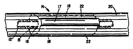
As shown in Figures 2-4, the lead 10 of the present
invention includes a coil-shaped conductor member 12
which surrounds a lumen 13. The ring electrode 14 is
coupled to the coil-shaped conductor member 12. This
will preferably be accomplished using an axial laser weld
between the conductor member 12 and the ring electrode
14.
One important feature of the present invention is
the shape of the ring electrode 14. The ring electrode
14 has a generally cylindrical-shaped channel 15 (defined
by a wall 16) through its center. During assembly, the
coil-shaped conductor member 12 is inserted through the
cylindrical-shaped channel 15. An axial laser weld is
then used to join the conductor member 12 to the wall 16
of ring electrode 14. The outer surface 17 of the ring
electrode 14 is not cylindrical. Instead, it includes
one or more slots 18 which extend from one end of the
ring electrode 14 to the other. The drawings show three
slots 18. However, the number of slots 18 can be as few
as one. There is no upper limit to the umber of slots
18. Practically speaking, three to four slots 18 should
be adequate.
CA 02339135 2001-O1-30
-- . WO 00/06247 PCT/US99/17304
-5-
Once the ring electrode 14 and conductor member 12
have been joined together, an insulative covering 20 can
be applied. This coating is typically made of silicone,
but other materials having insulative characteristics
could also be used. When properly applied, the covering
20 covers both the proximal and distal portions of the
conductor and fills the slots 18 to create connecting
bridges 22 across the length of the ring electrode 14.
The bridges 22 are integrally formed with the proximal
and distal portions of covering 20 and thus serve to
strengthen the joints between the ring electrode 14 and
covering 20. Of course, the non-slotted portions of the
outer surface 17 of the ring electrode 14 remain exposed
and uninsulated to provide a current path. To reduce
voltage thresholds for the ring electrode 14, the
silicone covering 20 could be loaded with a steroid such
as, for example, dexamethasone sodium phosphate or
dexamethasone acetate. Other suitable steroids may also
be used.
Figure 5 is a cross-sectional view of a second
embodiment. In this embodiment, the conductor member 12
is surrounded by an insulative covering 20. The
insulative covering 20 can be made of silicone rubber or
any other suitable material. In this embodiment, the
ring electrode 14 has a cylindrical outer surface 17.
However, the inner wall 16 is not cylindrically shaped.
Instead, one or more teeth 24 are provided. The teeth 24
extend toward the conductor member 12 and are used to
weld the conductor member 12 to the ring electrode 14.
The teeth are separated by slots 19. These slots 19
extend the length of the ring electrode 14 and are filled
to form a bridge 23 integrally formed with and made of
the same material as the covering 20. In this
embodiment, the bridges 23 cooperate with the teeth 24
and with the remainder of the covering 20 to improve the
axial strength of the joints between the covering 20 and
ring electrode 14.
CA 02339135 2001-O1-30
-. WO 00/06247 PCT/US99/17304
-6-
Figure 6 shows a third embodiment. This embodiment
again includes a conductive member 12, an insulative
covering 20 and a ring electrode 14. In this embodiment,
however, neither the wall 16 nor the inner surface 17 are
cylindrical. Instead, the wall 16 includes teeth 34
separated by slots 19. The outer surface 17 also
includes slots 18 extending into the areas of the ring
electrode 14 incorporating the inwardly projecting teeth
34. Thus, when the insulative covering 20 is formed,
inner bridges 23 are formed in the slots 19 between the
teeth 34 and outer bridges 22 are formed in the slots 18
which extend into the teeth 34. Since the slots 18 and
19 extend the entire length of the ring electrode 14, the
bridges 22 and 23 are integrally formed with the portions
of the covering 20 proximal and distal to the ring
electrode 14.
Electrodes incorporating the features of the present
invention have significant advantages over prior art
electrodes. First, electrodes made in conformance with
the present invention eliminate weak joints between the
electrode and the insulative covering. Second, such
electrodes accomplish this while minimizing the rigid
length of the electrode resulting in greater flexability
of the lead design. Thus, leads made in accordance with
the present invention are well suited for situations when
placement of the electrode requires it to be advanced
through the vasculature, such as when the electrode is to
be placed in the great vein of the heart in proximity to
the left ventricle or in either the right ventricle or
right atrium.