Note: Descriptions are shown in the official language in which they were submitted.
CA 02339359 2001-02-02
WO 00/08676 PCT/US99/17649
-1-
WORKPIECE VIBRATION DAMPER
Background
This invention relates to apparatus for supporting a workpiece, e.g., a
semiconductor wafer, in a precision processing system, such as a focused ion
beam
system or an electron microscope system. Focused ion beam (FIB) systems can
both
image and etch, e.g., micromachine, a workpiece. Existing FIB systems commonly
support a workpiece on fixed, rigid workpiece contact elements.
Unless firmly clamped, workpieces such as wafers held in an FIB machine or
electron microscope tend to vibrate in the spans between the rigid workpiece
contact
elements. This is a particular problem in the acoustic environment of wafer
fabrication
plants. Wafer vibration can cause image degradation or produce defects during
micromachining.
In addition, wafers are often somewhat curved. Having a curved wafer increases
focusing problems for a precision processing system. Under atmospheric
conditions, a
precision processing system can firmly clamp a wafer by drawing a partial
vacuum
underneath the wafer. The reduced pressure pulls the wafer into contact with a
backing
plate, with atmospheric pressure acting over the entire wafer surface. Firm
clamping via
partial vacuum reduces wafer curvature, as the wafer contacts the backing
plate in
numerous locations. Further, the largest unsupported span of the wafer is
short and
possible vibration frequencies for the wafer are high.
Often precision processing systems, such as an FIB system, place a wafer in a
vacuum for processing. In vacuum, the above-described partial vacuum clamping
method is not available. Precision processing systems can use electrostatic
forces as a
substitute for the partial vacuum clamp. As with a partial vacuum clamp,
electrostatic
forces can act over the entire wafer surface. However, there are significant
disadvantages. The equipment to achieve such electrostatic forces is expensive
and
generally does not produce forces of high magnitude. High voltage breakdown
can
CA 02339359 2001-02-02
WO 00/08676 PCT/US99/17649
-2-
occur and damage the wafer. The resulting electrostatic field can undesirably
deflect the
ion or electron beam. In addition, a system using electrostatic forces can
have difficulty
releasing the wafer when the source for generating the electrostatic forces is
turned off.
Precision processing systems can apply mechanical clamping as a substitute for
electrostatic forces. However, applying mechanical clamping to the wafer
surface
anywhere but at the edge of the wafer can occlude and damage the work area. In
addition, mechanical clamping at the edge of the wafer does not ensure that
the wafer,
which is usually somewhat curved or otherwise not absolutely planar, will
contact a
substantially flat backing plate anywhere except at the edges or other
fragmentary
portions of the wafer. The backing plate can be designed with a greater
curvature than
the largest curvature possible in a wafer. However, having a curved backing
plate and a
correspondingly curved wafer increases focusing problems for a precision
processing
instrument.
It is an object of the invention to provide apparatus for supporting a
workpiece in
a precision FIB system.
It is another object of the invention to provide workpiece supporting
apparatus
that reduces workpiece vibration.
It is another object of the invention to provide workpiece supporting
apparatus
that is relatively easy and inexpensive to manufacture and to repair.
It is another object of the invention to provide workpiece supporting
apparatus
that operates effectively in a vacuum. Other objects of the invention will in
part be
obvious and will in part appear hereinafter.
CA 02339359 2001-02-02
WO 00/08676 PCTNS99/17649
-3-
Summary of the Invention
Apparatus according to this invention supports a workpiece in a precision
processing instrument, e.g., in an FIB system or in an electron microscope
system.
In one preferred embodiment, a workpiece supporting apparatus includes a
plurality of
workpiece contact elements and a compliant stiction support carried on a base
member.
The workpiece contact elements maintain the workpiece substantially in a
plane. The
compliant stiction support stiffly supports the workpiece against vibrational
forces and
thus reduces vibration of the workpiece.
When a workpiece is placed on the workpiece contact elements and the
compliant stiction support, the stiction support is depressed under the weight
of the
workpiece. Once the stiction support comes to rest, after being depressed by
the
workpiece, the stiction support must overcome static friction in order to move
again.
The compliant stiction support is located substantially in the plane formed by
the
workpiece contact elements.
A compliant stiction support, according to one embodiment of the invention,
includes a slider assembly for contacting the workpiece. The slider assembly
is in
sliding, frictional connection with the base member. For example, in one
embodiment,
the slider assembly is slidably mounted in a slider containing cavity in the
base member.
According to this embodiment, the compliant stiction support has a workpiece
contact
spring element between the slider assembly and the bottom of the slider
containing
cavity in the base member. The workpiece contact spring element resiliently
urges the
slider assembly into contact with the workpiece. When the slider assembly,
under the
weight of the workpiece, compresses the workpiece contact spring element, the
spring
element provides a force not greater than the force necessary to support the
weight of the
workpiece. Thus, a portion of the weight of the workpiece is carried by the
workpiece
contact elements. In a preferred embodiment, the compressed workpiece contact
spring
element provides a force sufficient to support approximately half the weight
of the
workpiece while the workpiece is concurrently supported by the workpiece
contact
CA 02339359 2001-02-02
WO 00/08676 PCT/US99/17649
-4-
elements. This preferred embodiment ensures contact of the workpiece with the
workpiece contact elements.
The compliant stiction support can further include a stiction spring element
for
forcing the slider element into frictional contact with the base member. In
one
embodiment, the stiction spring element is in contact with the base member and
the
slider element. The suction spring element forces the slider element into
frictional
contact with the base member. In a preferred embodiment, the stiction spring
element in
operation provides a force on the slider element substantially equal to the
force provided
by the compressed workpiece contact spring element on the slider assembly. The
slider
element and the base member have a coefficient of static friction preferably
between 0.1
and 0.7 and most preferably between 0.2 and 0.6. In an alternative embodiment,
apparatus according to the invention can include a plurality of compliant
stiction
supports.
One preferred embodiment of the invention contemplates a stage having a
plurality of rigid workpiece contact elements located near the edges of the
workpiece
and a compliant stiction support located between the rigid workpiece contact
elements.
The compliant stiction support has a slider at least partially contained by a
slider-
containing cavity in the base member. A workpiece contact spring is located
between
the bottom of the slider and the bottom of the slider-containing cavity. The
slider has a
stiction spring-containing cavity with an opening facing the side wall of the
slider-
containing cavity. A suction spring is at least partially contained in the
stiction spring-
containing cavity in the slider.
Thus, when a workpiece is placed on the rigid workpiece contact elements, it
contacts the slider of the compliant stiction support and depresses the
workpiece contact
spring. The slider moves downward in contact with the workpiece. The stiction
spring
element pushes the slider against the surface of the slider-containing cavity,
resulting in
friction between the slider and the surface of the slider-containing cavity.
The friction
CA 02339359 2001-02-02
WO 00/08676 PCT/US99/17649
-5-
between the slider and the surface of the slider-containing cavity reduces the
vibration of
the slider and the portion of the workpiece supported by the slider.
These and other features of the invention are more fully set forth with
reference
S to the following detailed description, and the accompanying drawings.
Brief Description of the Drawings
Figure 1 is a schematic representation of a focused ion beam system including
apparatus for supporting a workpiece according to the present invention;
Figure 2 is cross-sectional view of a portion of the apparatus for supporting
a
workpiece shown in Figure 1;
Figure 3 is a top plan view of a portion of the apparatus for supporting a
workpiece shown in Figure 1;
Figure 4 is cross-sectional view of a compliant stiction support of the
workpiece
supporting apparatus shown in Figure 1;
Figure 5 is a cross-sectional view of a stiction assembly of the compliant
stiction
support of Figure 4 shown along line 5-5.
Figures 6A-6C are graphical representations of the relationship between the
forces acting on, and the velocity of, the slider of the compliant stiction
support of
Figures 1 and 2;
Figure 7 is a top plan view of an alternative embodiment of a portion of the
workpiece supporting apparatus shown in Figure 1; and
Figure 8 is a top plan view of another alternative embodiment of a portion of
the
workpiece supporting apparatus shown in Figure 1.
CA 02339359 2001-02-02
WO 00/08676 PCTNS99/17649
-6-
Description of Illustrated Embodiments
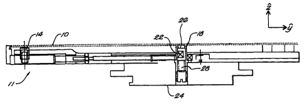
Figure 1 shows apparatus 11 for supporting a workpiece 10 in one type of
precision processing system, i.e., an FIB system 12. U.S. Patent No.
4,874,947, issued
to Ward et al. and incorporated herein by reference, contains a more detailed
description
of an FIB system. Figures 2 and 3 are views of a portion of the apparatus 11
for
supporting a workpiece 10 shown in Figure 1. In Figures 1-3, the apparatus 11
includes
a single compliant stiction support 18 in the middle of a workpiece 10 held
lightly near
its edges. Figures 4 and S are views of at least a portion of the compliant
stiction
support 18 shown in Figures 1-3. Additional compliant stiction supports can be
employed for larger workpieces as illustrated in Figure 7. As illustrated in
Figures 1-4,
and 5, the workpiece 10 is supported substantially in a horizontal plane,
i.e., the plane
defined by the indicated X and Y axis. However, the apparatus according to the
present
invention is not limited to supporting the workpiece in a horizontal plane.
For example,
a precision processing system with a tilting stage can incorporate the present
invention.
With reference to Figures 2, 4 and 5, the illustrated compliant stiction
support 18
stiffly supports a workpiece 10 against vibrational forces. When a precision
processing
system or a user places a workpiece 10 on workpiece contact elements 14, the
workpiece
depresses a slider element 26 of the compliant stiction support 18. The slider
element, in
turn, compresses a light workpiece contact spring element 28. When compressed,
the
spring element 28 preferably provides a force sufficient to support half the
weight of the
workpiece.
A stiction spring element 22 pushes the slider element 26 against the
(grounded)
stiction surface 19 of its containing cavity 21, causing a static friction
("stiction") lock to
ground for the portion on the workpiece l0a supported by the compliant suction
support
18. The coefficient of static friction between the stiction surface 19 and the
slider
element 26 is less than approximately 0.5. The force exerted by the stiction
spring
element 22 is approximately equal to the force provided by the compressed
wafer
contact spring element 28. With the above-described configuration, the
compliant
CA 02339359 2001-02-02
WO 00/08676 PCT/US99/17649
stiction support 18 supports the workpiece while concurrently reducing
relatively small
magnitude vibration of the workpiece.
The maximum stiction force of the illustrated stiction support 18 is
preferably
between approximately 1 % and 20%, and most preferably is between 5% and 15%
of the
weight of the workpiece. A stiction force in the above-described ranges
reduces
relatively high frequency vibrations while allowing the stiction support to
remain
compliant to the weight of the workpiece. For example, the exciting vibrations
encountered in a wafer fabrication environment are on the order of 0.1 % of
the weight of
a wafer. Therefore, the above-described maximum stiction force is more than
sufficient
to immobilize a portion of a wafer.
Figures 6A-6C illustrates the relationship between the forces acting on, and
the
velocity of, the slider of the complaint stiction support 18. The non-
frictional forces
include forces provided by the weight of the workpiece 10 and by the contact
spring
element 28. The vibrational forces can have a variety of sources including
fans located
near the apparatus 11.
As illustrated in Figures 6A-6C, and on page 290 of J.P. DenHartog's
Mechanical
Vibrations, 1956, McGraw-Hill, incorporated herein by reference, in dry
friction,
rubbing elements remain fixed {zero relative velocity) until the driving force
reaches a
"maximum stiction force" 40, 41 at which point relative motion begins, and the
friction
force falls to a value 42, 43 that is independent of velocity.
When a workpiece 10 is loaded, as illustrated in Figure 6A, the force provided
by
the workpiece's weight, represented by arrow 44, minus the force provided by
the
contact spring, represented by arrow 45, is greater by an amount 48 than the
maximum
stiction force, represented by point 41, and the workpiece 10 compresses the
contact
spring element 28. The workpiece 10 comes to rest on the workpiece contact
elements
14, which support a fraction of the workpiece's weight. The situation in which
the
workpiece is supported by the workpiece contact elements 14 and the compliant
stiction
CA 02339359 2001-02-02
WO 00/08676 PCTNS99/17649
_g_
support 18 is illustrated in Figure 6B. The fraction of the weight carried by
the stiction
support provides a force, represented by arrow 46, on the stiction support 18.
In the
situation illustrated in Figure 6B, the force 46 minus the contact spring
force,
represented by arrow 47, is insufficient to overcome static friction and the
workpiece is
supported with the slider remaining motionless.
In Figure 6C, the workpiece weight is removed, and the contact spring force,
represented by arrow 49, overcomes static friction to move the slider element
upward.
The maximum force of static friction is determined by the force provided by
the stiction
spring element 22 and the coefficient of static friction between the slider
element 26 and
the stiction surface 19 of the containing cavity 21.
Once the slider element 26 comes to rest after being compressed by the
workpiece, the slider element will not vibrate normal to the plane of the
workpiece,
unless vibrational forces in combination with the contact spring force exceed
the
maximum force of static friction. To the extent that the workpiece remains in
contact
with the slider element, when the slider element does not vibrate the portion
of the
workpiece supported by the slider element will not vibrate.
Figure 7 is a top plan view of an alternative embodiment of a workpiece
supporting apparatus according to the present invention including more than
one
compliant stiction support 18. The compliant stiction supports 18 are
substantially
within the plane formed by the workpiece contact elements 14. In other words,
in one
embodiment, the workpiece contact elements 14 form a substantially horizontal
plane.
The invention, according to a preferred embodiment, locates the supports 18 to
most effectively reduce workpiece vibration. One embodiment of the invention
places
the supports 18 in the middle of the larger unsupported spans of the workpiece
10.
When a precision processing system uses a plurality of compliant stiction
supports, the
aggregate force provided by the compressed workpiece contact spring elements
preferably does not substantially exceed the force necessary to support half
the weight of
CA 02339359 2001-02-02
WO 00/08676 PCT/US99/17649
-9-
the workpiece. As many compliant stiction supports 18 can be fitted to a
workpiece
supporting apparatus as are necessary to reduce movement of the unsupported
spans
between the workpiece contact elements 14, and thus to limit the resonant
frequencies of
the wafer vibration modes.
Preferably, the workpiece contact elements 14 in aggregate support at least a
quarter of the weight of the workpiece and the stiction supports 18 in
aggregate support
at least a quarter of the weight of the workpiece. Most preferably, the
workpiece contact
elements 14 in aggregate support approximately half the weight of the
workpiece and the
stiction supports 18 in aggregate support approximately half the weight. If
the contact
elements 14 support too much of the weight of the workpiece, the workpiece can
be
susceptible to high frequency vibration. If the stiction supports 18 support
too much of
the weight of the workpiece, the workpiece as a whole could move in response
to
disturbances.
With reference to Figure 8, another alternative embodiment of a workpiece
supporting apparatus according to the present invention includes more than
three
workpiece contact elements 14. In the illustrated embodiment, the workpiece
supporting
apparatus includes four workpiece contact elements and one centered compliant
stiction
support 18. The invention contemplates any useful number, combination, and
placement
of workpiece contact elements and compliant stiction supports. More contact
elements
and stiction supports can be advantageous when processing a relatively large
workpiece.
Again, most preferably, the workpiece contact elements 14 in aggregate support
approximately half the weight of the workpiece and the stiction support 18
supports
approximately half the weight.
It will thus be seen that the objects set forth above, among those made
apparent
from the preceding description, are officially attained. Since certain changes
may be
made in the above constructions without departing from the scope of the
invention, it is
intended that all matter contained in the above description and shown in the
accompanying drawings be interpreted as illustrative and not in a limiting
sense. It is
CA 02339359 2001-02-02
WO 00/08676 PCf/US99/17649
-10-
also to be understood that the following claims are intended to cover all
generic and
specific features of the invention described herein, and all statements of the
scope of the
invention which as a matter of language might be said to fall therebetween.
$ Having described the invention, what is claimed as new and secure by letters
patent is: