Note: Descriptions are shown in the official language in which they were submitted.
CA 02339864 2001-02-07
WO 00109204 PCTNS99/18389
EXPANDABLE SEAL FOR USE WITH
MEDICAL DEVICE AND SYSTEM
The present invention relates generally to medical devices, such as leads
and catheters. More particularly, it pertains to expandable seals for medical
devices such as leads and catheters.
to Invent,
Leads implanted in or about the heart have been used to reverse (i.e.,
defibrillate or cardiovert) certain life threatening arrhythmias, or to
stimulate
contraction (pacing) of the heart. Electrical energy is applied to the heart
via the
leads to return the heart to normal rhythm. Leads have also been used to sense
in
the atrium or ventricle of the heart and to deliver pacing pulses to the
atrium or
ventricle. The same lead used to sense the condition is sometimes also used in
the process of delivering a corrective pulse or signal from the pulse
generator of
the pacemaker.
Cardiac pacing may be performed by the transvenous method or by leads
implanted directly onto the ventricular egicardium. Most commonly, permanent
transvenous pacing is performed using a lead positioned within one or more
chambers of the heart. A lead, sometimes referred to as a catheter, may be
positioned in the right ventricle or in the right atrium through a subclavian
vein,
and the lead terminal pins are attached to a pacemaker which is implanted
subcutaneously. The lead may also be positioned in both chambers, depending
on the lead, as when a lead passes through the atrium to the ventricle. Sense
electrodes may be positioned within the atrium or the ventricle of the heart.
Pacemaker leads represent the electrical link between the pulse generator
and the heart tissue which is to be excited. These pacemaker leads include
single
or multiconductor coils of insulated wire having an insulating sheath. The
coils
provide a cylindrical envelope, many times referred to as a lumen, which
provides a space into which a stiffening stylet can be inserted. The
conductive
coil is connected to an electrode in an electrode assembly at a distal end of
a
pacing lead.
CA 02339864 2001-02-07
wv uwvy~uw .. YC:T/US99/18389 _
After the electrode assembly is positioned at a desired location within the
heart, it is desirable to provide some method for securing the electrode
assembly
at that location. One approach is to use a passive device which has structure
to
allow for tissue growth surrounding the structure to affix the electrode
assembly
5 . to the heart. Another approach is to use an active device where mechanical
fixation devices are used to firmly anchor the electrodes in the heart. One
type
of mechanical fixation device used is a corkscrew, or a helix. During
placement
of the lead, the tip of the lead travels intravenously through veins and the
heart.
While traveling through the veins, the helix at the tip of the lead may snag
or
10 attach to the side wall of the vein. Since this is highly undesirable as it
may
cause damage or other complications to a patient, retractable helixes have
been
provided for leads.
The practitioner must maintain the electrode pressed against the wall of
the cavity before shifting the screw. When the screw is shifted, the electrode
15 may be correctly in contact with the wall, and the fixation screw, as it
travels out
of the body of the electrode, penetrates and becomes hooked in the tissue of
the
wall. Alternatively, the electrode may stop short of the wall of the cavity
and it
may be necessary for the practitioner to start again by retracting the screw
and
then turning the helix out again into the cardiac tissue. Thus, it is
important for
20 the helix to rotate freely within the electrode.
During use, the lead provides and receives critical information to and
from the heart. The lead, therefore, must remain in suffcient operative
condition
without interference from entry of bodily fluids. To prevent entry of bodily
fluids into the lead, a seal can be provided at the distal end of the lead.
25 Conventional leads often use 0-rings or puncture seals to seal the distal
end of
the lead from entry of bodily fluids. The O-ring seals can be difficult to
manufacture due to dimensional constraints which also affects the
extensionlretraction mechanism of the lead, as well as the effectiveness of
the
seal. Puncture seals also may increase the difficultly of using the helix,
since the
30 helix needs to puncture the seal and the puncture seals can increase the
friction
between the extension mechanism and the seal. The friction makes it more
di~cult to extend or retract the extension mechanism and the helix. In
addition, the structural integrity of the puncture seal can be jeopardized if
the
2
CA 02339864 2001-02-07
WO 00/09104 - PCT/US99/18389
seal continues to tear fi-om repeated movement and/or stress from the fixation
screw.
Accordingly, there is a need for a lead which is sufficiently sealed from
the environment. What is further needed is a seal which does not interfere
with
. the extension and retraction bf the helix.
A body-implantable lead assembly is provided comprising a lead, one
end being adapted to be connected to an electrical supply for providing or
receiving electrical pulses. The lead further comprises a distal tip which is
adapted to be connected to tissue of a living body. The lead also has a sheath
of
material inert to body materials and fluids and at least one conductor
extending
through the lead body.
The distal tip electrode is adapted for implantation proximate to or within
the heart while connected with a system for monitoring or stimulating cardiac
1 S activity. In another embodiment, the distal tip electrode assembly is
adapted for
implantation proximate to the heart while connected with a system for
monitoring or stimulating cardiac activity. The distal tip electrode includes,
in
one embodiment, an electrode tip, a mesh screen disposed at a distal end of
the
electrode tip, a fixation helix disposed within the electrode tip, and a
hydrogel
seal. The helix is retractable, and is in contact with a movement mechanism.
The movement mechanism provides for retracting the helix, such as during
travel
of the electrode tip through veins. In another embodiment, the electrode tip
further includes a piston for moving the helix. The piston can further include
a
slot for receiving a stylet. When engaged and rotated, the piston provides
movement to the helix. The piston is coated with the hydrogel seal, in one
embodiment, which is adapted to expand upon contact with bodily fluid.
In another configuration, a distal tip electrode is provided which is
adapted for implantation proximate to the heart, while optionally connected
with
a system for monitoring or stimulating cardiac activity. The distal dp
electrode
includes a seal comprised of an expandable matrix which is adapted to expand
upon contact with fluid. The seal can be in the foam of a plug which is
inserted
into the electrode, or a medical device, using an advancing tool. The plug can
be
molded of the expandable material into a variety of shapes, for instance a
ring, or
3
CA 02339864 2001-02-07
w~ uwuyiu4 .. PCT/US99118389_
including a tapered surface. The ring shape can also be used for surrounding
an
internal lead structure disposed within the lead. The plug can optionally
include
features which frictionally engage an encompassing surface and prevent
premature removal of the advancing tool. In another embodiment, the seal is in
5 the form of an end cap which is affixed to the distal tip of the electrode.
Alternatively, the expandable matrix is disposed on the interior of a housing
which is secured to the electrode.
The provided medical device, which includes an electrode tip, supplies an
extension/retraction mechanism which is sealed finm exposure to fluids. The
10 lead avoids deterioration of its function by entry of liquid inside the
lead, owing
to the provision of a highly effective seal which does not interfere with the
helix.
In addition, the seal remains functional when the lead is removed for short
periods of time from an environment filled or partially filled with fluid. Yet
another advantage is that the lead and the seal permit rotating the
15 extension/retraction mechanism until it penetrates the cardiac tissue
without
limitation on the number of rotations until proper anchorage has been
achieved,
and without significant friction imparted to the extension/retraction
mechanism.
These and other embodiments, aspects, advantages, and features of the
present invention will be set forth in part in the description which follows,
and in
20 part will become apparent to those skilled in the art by reference to the
following
description of the invention and referenced drawings or by practice of the
invention. The aspects, advantages, and features of the invention are realized
and attained by means of the instrumentalities, procedures, and combinations
particularly pointed out in the appended claims and their equivalents.
25 Brief Deccrintion of the Drawings
Figure 1 is a side elevational view illustrating a lead constructed in
accordance with one embodiment of the present invention.
Figure 2 is a cross-sectional view of an electrode tip of a lead for
monitoring and stimulating the heart constructed in
30 accordance with one embodiment of the present invention.
Figure 3A is a cross-sectional view of an electrode tip of a lead for
monitoring and stimulating the heart constructed in
accordance with one embodiment of the present invention.
4
CA 02339864 2001-02-07
WO 00/09204 ~~ PCTNS99I18389
Figure 3B is a cmss-sectional view of an electrode tip of a lead for
monitoring and stimulating the heart constructed in
accordance with one embodiment of the present invention.
Figure 4 is a cross-sectional view illustrating a system for
delivering signals to the heart constructed in accordance
with one embodiment of the present invention.
Figure 5 is a table illustrating the expansion for the expandable
matrix constructed in accordance with one embodiment of
the present invention.
Figure 6 is a table illustrating the amount of expansion for the
expandable matrix constructed in accordance with another
embodiment of the present invention.
Figure 7 is a perspective view of a plug for sealing a medical
device constructed in accordance with one embodiment of
the present invention.
Figure 8 is a cross-sectional view of a lead for monitoring and
stimulating the heart constructed in accordance with one
embodiment of the present invention.
Figure 9 is a cross-sectional view of a lead for monitoring and
stimulating the heart constructed in accordance with one
embodiment of the present invention.
Figure 10 is a cross-sectional view of a lead for monitoring and
stimulating the heart constructed in accordance with one
embodiment of the present invention.
Figure 11 is a cross-sectional view of a lead for monitoring and
stimulating the heart constructed in accordance with one
embodiment of the present invention.
Figure 12 is a cmss-sectional view of a lead for monitoring and
stimulating the heart constructed in accordance with one
embodiment of the present invention.
Figure 13 is a cross-sectional view of a lead for monitoring and
stimulating the heart constructed in accordance with one
embodiment of the present invention.
5
CA 02339864 2001-02-07
w v vuivycuw .- PCT/US99/18389 _
In the following detailed description, reference is made to the
accompanying drawings which form a part hereof, and in which is shown by way
of illustration specific embodiments in which the invention may be practiced.
S These embodiments are described in sufficient detail to enable those skilled
in
the art to practice the invention, and it is to be understood that other
embodiments may be utilized and that structural changes may be made without
departing from the spirit and scope of the present invention. Therefore, the
following detailed description is not to be taken in a limiting sense, and the
10 scope of the present invention is defined by the appended claims and their
equivalents.
One embodiment of a lead 10 is illustrated in Figure 1. The lead 10, in
one embodiment, comprises a lead body 11, and extends from a proximal end 32
to a distal end 30. An elongate conductor is contained within the lead body
11,
15 and a lead tip 20 is disposed proximate the distal end 30. In one
embodiment, an
electrode tip assembly 24 is contained in the lead tip 20 (Figure 2). In
another
embodiment, the lead tip 20 comprises an open lumen lead tip (Figures 3A and
3B). In addition, a stylet 14 is shown, which in one embodiment is inserted
into
the lead body 11.
20 A helix 100 (Figure 2) comprises an electrical conductor coil, is
contained in the retractable lead tip assembly 24, in another embodiment. The
helix 100 extends and retracts by rotation of the stylet 14, as will be
discussed
fiirther below. Although a brady lead body is shown, other medical devices or
other leads, such as tachy leads could also be used. In one embodiment, the
lead
25 body 11 is at least partially covered by a biocompatible insulating
material 22.
Silicone rubber or other insulating material can be used for covering the lead
body 11.
In one embodiment, the helix 100 is fon~ned of electrically conductive
material offering low electrical resistance and which is also resistant to
corrosion
30 by body fluids. In another embodiment, the helix 100 may be coated with an
insulative material. A platinum-iridium alloy is an example of a suitable
conductive material. Another example is a conductive helix partially coated
with
Parylene. The Parylene insulative coating effectively increases in vitro
"pacing
6
CA 02339864 2001-02-07
WO 00/09204 .- PC'TNS99/18389 _
impedance". Application of Parylene to the metallic fixation helix produces
the
desired increase in impedance compared to an uninsulated helix as well as
other
existing designs. Alternatively, in another configuration, the helix 100 is
electrically inactive. The helix 100 can be made electrically active or
inactive to
change sensing and pacing characteristics as needed.
Referring to Figure 2, the helix 100 of the lead 10, in one embodiment,
defines a lumen 102 therethrough and thereby is adapted to receive a
stiffening
stylet 14 that extends through the length of the lead 10. The lumen 102,
however, can also be defined by other portions of the electrode tip assembly
24.
The stylet 14 (Figure 1) stiffens the lead 10, and can be manipulated to
introduce
an appropriate curvature to the lead 10, facilitating the insertion of the
lead 10
into and through a vein and through an intracardiac valve to advance the
distal
end 30 of the lead 10 into the heart, for example into the right ventricle of
the
heart. A stylet lrnob 12 (Figure 1) is coupled with the stylet 14 for rotating
the
stylet 14 and advancing the helix 100 into tissue of the heart.
In another embodiment, the lead 10 has an electrode tip 120 which is
provided with a mesh screen 130. The mesh screen 130 covers at least a portion
of an end surface 112 of the lead 10, and serves as the pacing/sensing
interface
with cardiac tissue. If the helix 100 is electrically active, it too can help
serve as
a pacing or sensing interface. The mesh screen 130 is of a porous
construction,
made of electrically conductive, corrosion resistant material. Using a mesh
screen 130, for example having a porous construction, advantageously allows
for
fibrotic ingrowth. This provides for a further anchoring of the electrode tip
120
and also increases the sensing capability of the lead I 10 by increasing the
surface
area in contact with the cardiac tissue. The impedance of the mesh screen can
be
also controlled by providing a partially insulating mesh screen. The mesh
screen
130, in one embodiment, is attached to an electrode collar 132, which can be
electrically active.
Disposed within the lead 10, in one embodiment, is a lead fastener for
securing the lead 10 to cardiac tissue. The lead fastener can be disposed
along
the radial axis 15 (Figure 2) of the electrode lead 10. In one embodiment, the
lead fastener comprises a fixation helix 100. The fixation helix 100 can be
made
electrically active or inactive as discussed above. Using a conductor coil
such as
7
CA 02339864 2001-02-07
wm uwuyiu4 .- PCI'/US99118389 _
heiix 100 has been shown to be capable of withstanding constant, rapidly
repeated flexing over a period of time which can be measured in years. The
helix 100 is wound relatively tightly, with a slight space between adjacent
turns.
This closely coiled construction provides a maximum number of conductor turns
5 per unit length, thereby providing optimum strain distribution. The spirally
coiled spring construction of helix 100 also permits a substantial degree of
elongation, within the elastic limits of the material, as well as distribution
along
the conductor of flexing stresses which otherwise might be concentrated at a
particular point.
10 Attached to the fixation helix 100, in one embodiment, is a piston 150.
The piston 1SO has a stylet slot 154 which is configured to mate with the
bladed
locking stylet 14 at the stylet slot 154. The stylet slot 154 acts as an
interface
between the stylet 14 and the helix 100. The stylet 14, coupled the piston 150
at
the stylet slot 154, extends and retracts the fixation helix 100 when the
stylet 14
15 is rotated. The piston 150 can either be electrically active or inactive.
The
piston 150, in another embodiment, also has a base slot 152, which allows the
piston 1 SO to mate with a base 160. The helix 100 with or without the piston
form a movement mechanism which facilitates the implantation of the lead 10
into a heart.
20 Fitted with a knob 162, as shown in Figure 2, the base 160, in one
embodiment, mates with the base slot 152 of the piston 150. The base 160
serves as, a stop once the fixation helix 100 is fully retracted. The base
160,
which can be electrically conductive, is adapted to allow passage of a bladed
locking stylet 14 and attachment of electrode coils.
25 A housing 140, which is electrically conductive in one embodiment,
encapsulates the piston 150 and the fixation helix 100. In one embodiment, the
housing 140 is disposed about the piston 150, creating an annular gap 156
therebetween. Insulation (not shown) is disposed about the housing 140 and
collar 132. A suitable material for the insulation is, for example, silicone
rubber,
30 or other materials which are inert and well tolerated by body tissue are
also
appropriate. The housing 140 is coupled with the electrode collar 132 and
transmits electrical signals from the electrode collar 132 to the base 160.
8
CA 02339864 2001-02-07
WO 00/09204 - PCTNS99/18389
In another embodiment, the electrode tip 120 has a hydrogel seal 164
disposed therein. In one embodiment, the piston 150 is coated with the
hydrogel
seal 164. In another embodiment, a portion of the helix 100 is coated with the
hydrogel seal 164. For example, a tight-wound portion 151 of the helix 100 is
coated with the hydrogel seal 164. The hydrogel seal 164 is adapted to expand
upon contact with fluid and fill and seal off the annular gap 156 between the
piston 150 and the housing 140. In one embodiment, the seal 164 prevents any
blood flow through the electrode tip 120. Alternatively, in another
embodiment,
the seal 164 is adapted to limit the bodily fluid which passes past the seal
164.
The hydrogel seal 164 is comprised of material which expands upon contact of
fluid. One suitable type of material is a hydrophilic polymer, for example
poly
(2-hydroxyethyl methacrylate), polyvinyl alcohol, or polyethylene oxide. Other
examples, include Thermedics TECOGEL, Thermedics TECOPHILLIC, and
polyvinyl pyrrolidone. Alternatively, other materials which are expandable
upon
contact with fluid could also be used. Once expanded to fill the annular gap
156,
the hydrogel seal 164 is lubricious, thereby allowing rotation of the piston
150
and the helix 100 via the stylet 14.
The hydrogel seal 164 is not limited to a retractable lead, and can be used
on other medical devices such as catheters. Figures 3A and 3B illustrate
another
embodiment which includes an open lumen lead 180. The open lumen lead 180
has a lead body 182 extending to a lead tip 183, defining a lumen 184 therein.
The lumen 184 is defined by an inner surface 188 of the lead body 182. The
lumen 184 is used to manipulate the lead 180 over a guidewire (not shown).
Since no seal is typically provided, blood and other bodily fluids can enter
the
lumen 184, leading to complications. A hydrogel seal 186, in one embodiment,
is disposed on the inner surface 188 of the lead body 182, as shown in Figure
3A. The hydrogel seal 186 is adapted to expand upon contact with fluid and
fill
and seal off the lumen 184. In one embodiment, the seal 186 prevents any
further flow of blood or bodily fluid through the lead tip 183. Alternatively,
in
another embodiment, the seal 186 is adapted to limit the bodily fluid which
passes past the seal 186. The hydrogel seal 186 is comprised of material which
expands upon contact of fluid. Upon contact with fluid, the hydrogel seal 186
expands to fill the lumen 184 as shown in Figure 3B.
9
CA 02339864 2001-02-07
w~ uwuytu4 .- YCT/U599/18389
Figure 4 illustrates another embodiment, showing a view of a lead 200
adapted for delivering electrical pulses to stimulate the heart. The lead 200
is
not limited to any particular type of lead. The lead 200 extends from a
proximal
end 202, which is adapted to connect with equipment which supplies electrical
5 pulses, to a distal end 204 which is adapted to be inserted into the heart.
Proximate to the distal end 204 is an electrode tip 230. The electrode tip 230
includes a hydrogel seal or expandable matrix material (discussed below)
disposed therein. Upon contact with fluid, as discussed above, the hydrogel
seal
or the expandable matrix material absorbs the fluid and expands to prevent or
10 limit additional fluid from entering through the electrode tip 230.
A connector terminal 210 is disposed near the proximal end 202 of the
lead 200. The connector terminal 210 electrically connects the various
electrodes and conductors within the lead 200 to a pulse generator and signal
sensor 240. The pulse sensor and generator 240 contains electronics to sense
1 S various electrical signals of the heart and also produce current pulses
for delivery
to the heart, depending on the type of lead 200 used. The pulse sensor and
generator 240 also contains electronics and software necessary to detect
certain
types of arrhythmias and to correct for them. The lead terminal connector 210
provides for the electrical connection between the lead 200 and the pulse
20 generator 240.
In another configuration, an expandable matrix can be used to seal a
medical device, such as a lead tip assembly. The expandable matrix can be
molded and/or machined into a plug used as an external or internal seal, as
will
be further discussed below. Alternatively, the expandable matrix can be used
as
25 a coating on or in a base structure, which structure can be substantially
rigid.
The expandable matrix is biocompatible. The expandable matrix is adapted to
expand upon contact with a fluid, and is effective in sealing fluids from
further
entry into the medical device.
The composition of the expandable matrix, in one embodiment, generally
30 consists of at least one water permeable polymeric material in combination
with
one or more osmotically active agents. One example of a water permeable
polymeric material includes silicone. Other biocompatible elastomeric polymers
include polyvinyl alcohol or polyethylene oxide), or polyurethane. The
10
CA 02339864 2001-02-07
WO 00/09204 - PCTNS99/18389
expandable matrix includes at least one osmotically active agent such as,
glycerol, sodium chloride, or calcium chloride. Other equivalent agents can
also
be useful for forming the expandable matrix such as mannitol, glucose,
dextran,
potassium chloride, sodium phosphate, or any other non-toxic water soluble
S material that does not adversely affect curing of the water permeable
polymer.
The expandable matrix is adapted to absorb water upon contact with a
fluid environment. As water is absorbed, the matrix begins to swell in
physical
size and continues to swell until, in one embodiment, the osmotically active
agent is consumed. Alternatively, in another embodiment, the expandable
matrix swells until the internal pressure of the matrix is matched by a source
of
external pressure of, for example, the polymer or structure surrounding the
polymer. The rate of expansion and/or the amount of expansion can be
controlled by the selection of the polymer, the additive, and the particle
size of
the additive.
Other materials can be incorporated with the expandable matrix to yield
additional advantages or results. For example, in one embodiment, the
expandable matrix could incorporate a radiopaque material so that the matrix
can
be visualized using a fluoroscope. In another configuration, pharmacologic
additives can be incorporated with the expandable matrix such as dexamethasone
sodium phosphate, which would cause expansion of the matrix and provide local
pharmacologic therapy, such as anti-inflammatory action, thus improving the
biocompatibility of the device. Alternatively, additives which would promote
local blood coagulation can also be incorporated, such as calcium salts,
intrinsic
or extrinsic clotting factors.
The amount of osmotically active agent contained within the water
permeable polymeric material can be varied, depending on the desired results.
For instance, the rate of expansion or the total amount of expansion can be
controlled by varying the relative amounts of materials, which can be
determined
by testing the materials. In one embodiment, the weight content of the
osmotically active agent of the expandable matrix ranges from 2% - SO%. In
another embodiment, the weight content of the osmotically active agent of the
expandable matrix ranges from 10% - 40% by weight.
11
CA 02339864 2001-02-07
wu uuwylu4 .. PCT/US99/18389
In one embodiment, the total amount of expansion was measured for a
expandable matrix comprising water permeable polymeric material of silicone
(Dow Corning MDX-4-4210) with an osmotically active agent of glycerol. The
amount of glycerol, by weight percentage, was varied from 10% to 40%. The
5 results of this testing are summarized in Figures S and 6. Figure 5
illustrates the
change in diameter of two matrix compositions over time of exposure, which
shows that the fastest change in diameter occurs in the early stages of
exposure.
Figure 5 also illustrates that the fastest change in diameter, i.e., the
fastest rate of
expansion, occurred in the early stages of the 40% glycerol/silicone matrix.
10 However, this amount would vary for other water permeable polymeric
materials
and/or other osmotically active agents. These results demonstrate that the
rate of
expansion could be increased using increasing concentrations of glycerol.
Figure
5 also illustrates that the dimensions of the matrix containing 40% of
glycerol
returns to approximately the initial diameter with prolonged exposure to
fluid.
15 In contrast, the test sample containing 20% of glycerol maintains a stable,
expanded dimension over the same prolonged exposure time.
Figure 6 further compares final dimensions of the matrix material after
prolonged exposure for compositions ranging from 10% to 40% of glycerol,
measured by weight. Of the samples tested, a glycerol content of 40% yields
the
20 fastest expansion. However, a maximum stable, over time, expanded matrix
size
occurs with the matrix containing 20% of glycerol. Thus, the amount of
glycerol
content can be manipulated to modify the expansion of the expandable matrix
upon initial contact with fluid as well as contact with fluid over extended
periods
of time.
25 Figure 7 illustrates one embodiment incorporating the expandable matrix
as discussed above. A plug 300 is provided which, in one embodiment, is
molded from an expandable matrix which is adapted to expand upon contact
with fluid. Alternatively, the plug 300 can be coated with the expandable
matrix.
The plug 300 extends from a first end 312 to a second end 314, and, in one
30 embodiment, is generally cylindrically shaped. The first end 312 and the
second
end 314 define an intermediate portion 316 therebetween. In one embodiment,
the first end 312 includes a tapered portion 318. The tapered portion 318
12
CA 02339864 2001-02-07
WO 00/09204 -- PCT/US99/18389 _
facilitates implantation of the plug 300 into a medical device, or movement of
the plug through narrow passages.
The plug 300 is defined in part by an outer surface 320 which includes an
outer diameter 322. In one embodiment, proximate the second end 314, the plug
has a recess 328 therein. The recess 328 defines an inner diameter surface 324
and an advancing surface 326. The recess 328 is adapted, in one embodiment, to
receive an advancing tool (Figure 8) therein, as will be further described
below.
The inner diameter surface 324, in another embodiment, is adapted to fi-
ictionally
engage the advancing tool therein. Alternatively, the recess 328 can be
configured such that sufficient expansion of the plug 300 must occur before
the
advancing tool could be removed from the recess 328.
In one configuration, the outer diameter 322 of the plug 300 has at least
one rib 330 disposed thereon. The at least one rib 330 can be configured in
many different shapes. The at least one rib 330 is adapted to project firm the
outer surface 320 of the plug 300. As the plug 300 expands upon contact with
fluid, the at least one rib 330 interferes with further advancement of the
plug 300
through an enclosing surface and permits the plug 300 to expand to fill a
lumen
in which the plug 300 is disposed. As the plug 300 fiuther expands, the at
least
one rib 330 is compressed by an external surface of a lumen (Figure 8) in
which
the plug 300 is received. In one configuration, a plurality of ribs 332 are
provided, which, in one embodiment, extend longitudinally along the plug 300.
As the plurality of ribs 332 are compressed, the plug 300 is retained by the
enclosing surface to allow for removal of the advancing tool 460 (Figure 8)
therefrom.
Figure 8 illustrates another embodiment of the present invention. In this
configuration, a plug 400 is received within a medical device 440. The plug
400
is molded finm an expandable matrix which is adapted to expand upon contact
with fluid, as discussed above. Alternatively, the plug 400 is coated with the
expandable matrix. In one embodiment, the medical device 440 comprises a
lead 442 which is adapted to be implanted in or around the heart. The lead 442
comprises a number of configurations such as, although not limited to, those
described above and shown in Figures 1 - 4. Disposed within the lead 442 is a
coil 446, which is contained by an outer body 448, and the lead 442 has a
lumen
13
CA 02339864 2001-02-07
wu uuiuyzua .. PCT/U599/18389
444 therein. The plug 400 is adapted to seal the lumen 444 of the lead 442
upon
expansion of the plug 400, which prevents bodily fluids from entering through
the lead 442 and interfering with the performance of the lead 442.
The plug 400 extends from a first end 412 to a second end 414, and has a
5 tapered portion, in one embodiment, proximate to the first end 412. In
another
configuration, the plug 400 has a recess 428 therein, which is disposed
proximate
the second end 414. The recess 428 is adapted to receive a distal tip 462 of
an
advancing tool 460 therein. Once access through the lumen 444 is no longer
needed, the plug 400 can be positioned within the medical device 440. The
10 advancing tool 460 is used to move the plug 400 through the lumen 444 of
the
medical device 440 and position the plug 400 in an appropriate sealing
location.
The plug 400 and/or the recess 428 can be modified as in the previous
embodiment shown in Figure 7 to facilitate removal of the advancing tool 460.
After the plug 400 has been positioned within the medical device 440, the
15 advancing tool 460 can be removed. Upon contact with fluid, the plug 400
will
begin to expand and seal the lumen 444 of the medical device 440.
in another configuration, as shown in Figure 9, a plug 500 is provided
which is coupled with a medical device 540. The plug 500 is molded from an
expandable matrix which is adapted to expand upon contact with fluid, as
20 discussed above. Alternatively, the plug 500 is coated with the expandable
matrix. In one embodiment, the medical device 540 comprises a lead 542 which
is adapted to be implanted in or around the heart. The lead 542 can comprise a
number of configurations such as, although not limited to, those described
above
and shown in Figures 1 - 4. Disposed within the lead 542 is a coil 546, which
is
25 contained by a body having an outer diameter 548, and the lead 542 has a
lumen
544 therein. The lead 542 extends to a distal end 552 where it abuts the plug
500
at an attachment surface 520. The plug 500 is adapted to seal the lumen 544 of
the lead 542 upon expansion of the plug 500, which prevents bodily fluids from
entering through the lead 542 and interfering with the performance of the lead
30 542.
The plug 500 is molded from an expandable matrix which is adapted to
expand upon contact with fluid. Alternatively, the plug 500 is coated with the
expandable matrix. The plug 500 extends from a first end 512 to a second end
14
CA 02339864 2001-02-07
WO 00/09204 .. PC1'/US99/18389
S 14, and in one embodiment has an outer surface shaped as a cone 510. The
plug has a first inner diameter 522 proximate the first end 512 and a second
inner
diameter 524 proximate the second end 514. The second inner diameter 524 is,
in one embodiment, larger than the first inner diameter 522, forming a
shoulder
526 therebetween.
The coil 546 of the lead 542, in one embodiment, extends past the distal
end 552 of the lead 542 and is received by the second inner diameter 524 of
the
plug 500. The coil 546, in one embodiment, is affixed to the second inner
diameter 524 such that the coil 546 rests against the shoulder 526 of the plug
500. In another configuration, the coil 546 is fractionally engaged by the
surface
of the second inner diameter 524. In yet another embodiment, the coil 546 can
be attached to the lead 542 in a number of manners including medical adhesive.
As the plug 500 is exposed to fluids, the surface of the first inner
diameter 522 begins to grow smaller and smaller until a seal is created. Once
the
first inner diameter 522 has been eliminated by the expansion of the
expandable
matrix, the lumen 544 of the medical device 540 is effectively sealed off from
fiu-ther entry of fluids.
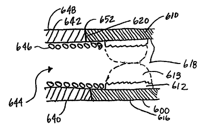
Illustrated in Figure 10 is another configuration, wherein a plug 600 is
provided which is coupled with a medical device 640. In one embodiment, the
medical device 640 comprises a lead 642 which is adapted to be implanted in or
around the heart. The lead 642 can comprise a number of configurations such
as,
although not limited to, those described above and shown in Figures 1 - 4.
Disposed within the lead 642 is a coil 646, which is contained by a lead body
having an outer diameter 648, and the lead 642 has a lumen 644 therein. The
lead 642 extends to a distal end 652 where it abuts the plug 600 at an
attachment
surface 620.
The plug 600 comprises a housing 610 having an outer diameter 616 and
an inner diameter 618. The housing 610 is formed from a rigid material has
expandable matrix material 612 disposed within the inner diameter 618, where
the expandable matrix material 612 is adapted to expand upon contact with
fluid,
as discussed above. The housing 610 can be attached to the medical device 640
in a variety of manners. For instance, in one configuration, the housing 610
is
laser welded to the medical device 640. Alternatively, other attachment
methods
CA 02339864 2001-02-07
wv vvwycv4 .. PCT/US99/18389 _
can also be used, such as resistance welding or adhesive bonding. The plug 600
is adapted to seal the lumen 644 of the lead 642 upon expansion of the plug
600,
which prevents bodily fluids from entering through the lead 642 and
interfering
with the performance of the lead 642.
5 The coil 646 of the lead 642, in one embodiment, extends past the distal
end 652 of the lead 642 and is received by the inner diameter 618 of the plug
600. The coil 646, in one embodiment, is affixed to the inner diameter 618.
The
coil 646 can be affixed to the inner diameter 618 using adhesive or mechanical
attachment methods. In another configuration, the coil 646 is frictionally
10 engaged by the surface of the inner diameter 618.
As the plug 600 is exposed to fluids, the expandable matrix material 612
swells and the inner diameter 618 begins to grow smaller and smaller until a
seal
613 is created. Once the inner diameter 618 has been eliminated by the
expansion of the expandable matrix, the lumen 644 of the medical device 640 is
15 effectively sealed off from further entry of fluids.
In another configuration, as illustrated in Figure 11, a medical device
such as a lead 700 is provided which has a cup 720 affixed thereto. The cup
720
comprises, in one embodiment, a thin-walled structure which is received by the
lead 700 around an outer diameter 728 of the cup 720. The cup 720 can be made
20 from biocompatible metal alloys and/or rigid polymers. In one embodiment,
the
cup 720 is attached at a distal end 702 of the lead 700, for example, by
welding
the cup 720 to the conductor coil 712 of the lead 700. Alternatively, the cup
720 can be attached to the lead 700 in other manners.
In another embodiment, the cup 720 includes a first inner diameter 722
25 and a second inner diameter 724, forming a shoulder 726 therebetween.
Molded
expandable material 740 is provided which rests upon the shoulder 726 until
expansion takes place. The molded expandable material 740 is formed from
expandable matrix material, as discussed above in previous embodiments. Once
the lead 700 has been implanted, and fluids contact the molded expandable
30 material 740, the material 740 expands until it contacts the surface of the
first
inner diameter 722. The molded expandable material 740 can be provided in a
variety of shapes to accommodate the interior surface of the cup 720. In one
configuration, the expandable material 740 is provided in the shape of a ring.
16
CA 02339864 2001-02-07
WO 00/09204 .- PCT/US99/18389 -
The ring shape allows for access to a lumen 710 of the lead 700 during
implantation, yet provides an effective seal after contact with fluid.
Figure 12 illustrates yet another configuration of a lead 800. The lead
800 has a lead body 810 containing a conductor coil 812 therein. The conductor
coil 812 defines a lumen 814 within the lead 800. Disposed within the lumen
814 of the lead body 810 is a secondary, internal lead structure 820 having,
in
one embodiment, a distal electrode 822 and a proximal electrode 824. An
annular gap 816 exists between the internal lead structure 820 and the
conductor
coil 812. A plug 840 (shown prior to expansion) is disposed between the
internal lead structure 820 and the conductor coil 812, where the plug 840 is
adapted to fill the gap 816 upon contact with fluid. In one configuration, the
plug 840 is molded of the expandable matrix as discussed in the earlier
embodiments. Upon contact with fluid, the plug 840 expands to the plug 842
and prevents further fluids from entering through the lumen 814 of the lead
800.
The plug 840 can be provided as a resident structure of the lead 800.
Alternatively, the plug 840 can be advanced through the lumen 814 using an
advancing tool (Figure 8), such as a stylet (not shown) after the internal
lead
structure 820 has been placed. The plug 840 advantageously seals the lumen
814, and also maintains the internal lead structure within the lumen 814. In
addition, the plug 840 allows for easy maneuvering of the internal lead
structure
820 during placement of the internal lead structure 820.
In Figure 13, another embodiment of a lead 900 is illustrated. The lead
900 has a lead body 910 encompassing, at least in part, a conductor coil 912.
A
portion of the conductor coil 912 is exposed thereby forming an exposed
electrode 914. The conductor coil 912 defines a lumen 916 therein. The lumen
916, in conjunction with a guidewire, for example, can be used to position the
lead 900 within the heart. However, the lumen 916 allows for entry of bodily
fluids into the lead 900, which may lead to complications.
A plug 920 is provided which seals off the lumen 916 after the lead 900
is properly positioned within the heart. The plug 920 is formed from the
expandable matrix material as discussed in the earlier embodiments. The plug
920, in another embodiment, could also include a steroid to reduce tissue
inflammation. Upon contact with bodily fluid, the plug 920 expands and seals
17
CA 02339864 2001-02-07
wu uwuyiua .- PCT/US99/18389
off the lumen 916. The plug 920 is sized and adapted to expand until it
occupies
enough of the lumen 916 to seal off harmful entry of fluids. The components of
the expandable matrix material forming the plug 920 can be modified to provide
the appropriate size plug as needed. The expanded plug 920 also provides
5 physical support to the exposed electrode 914 so that it is not
inadvertently
crushed.
To seal the lumen 916, the plug 920 must be properly positioned within
the lead 900. An advancing tool 922 is used, in one embodiment, to properly
position the plug 920 within the lead 900. Alternatively, the plug 920 can be
10 adapted to occupy the lead 900 as a resident structure, as discussed in the
earlier
embodiments. In one configuration, the advancing tool 922 has a predetermined
length which allows for the tool 922 to be inserted into the lead 900 at a
maximum of this predetermined length, which properly positions the plug 920
within the lumen 916. In another configuration, a limit stop, not shown, can
be
15 provided within the lumen 916 which prevents further insertion of the plug
920,
and alerts the physician that proper placement of the plug has occurred.
Advantageously, the hydrogel seal and the expandable matrix allow for
effective sealing of the medical device or the electrode lead upon contact
with
body fluid. The hydrogel seal does not significantly add to the friction when
a
20 physician or assistant rotates the stylet to rotate the piston, since the
expanded
hydrogel is lubricious, allowing movement of the internal components. The seal
blocks or limits body fluids which attempt to enter the lumen of the electrode
lead.
It is to be understood that the above description is intended to be
25 illustrative, and not restrictive. Many other embodiments will be apparent
to
those of skill in the art upon reading and understanding the above
description.
For instance, the seal can be used with a variety of medical devices. Although
the use of the lead has been described for use in a cardiac pacing system, the
lead
could as well be applied to other types of body stimulating systems. In
addition,
30 the lead could also be applicable to bipolar pacing leads having two
separate
conductors, and to multipoiar pacing leads employing multiple conductor leads.
The scope of the invention should, therefore, be determined with reference to
the
18
CA 02339864 2001-02-07
WO 00/09204 .- PC'T/US99118389_
appended claims, along with the full scope of equivalents to which such claims
are entitled.
19