Note: Descriptions are shown in the official language in which they were submitted.
CA 02339972 2001-02-08
WO 00/10264 PCT/US99/17947
CONVERSION AND DISTRIBUTION OF INCOMING WIRELESS
TELEPHONE SIGNALS USING THE POWER LINE
Backsround of the Invention
5 Field of the Invention. This invention relates to wireless telephone
communications
equipment. More specifically, this invention relates to equipment for
receiving,
converting and distributing wireless radio frequency signals using AC power
line
distribution channels.
Description of Related Art. A variety of power line carrier telephone voice
and/or
10 data communication systems have been developed and are used to facilitate
telephonic
communications in locations where little or no availability exists for
dedicated
telephone wires. While these devices provide a connection to the existing
power lines
they do not provide a means of distributing communication systems using
standard
"wired" telephone communication equipment and AC power line signal
distribution.
I S Such communication systems include: personal communication systems
("PCS=s"):
cellular telephone; and satellite telephone systems. The reader is directed to
the
following United States and foreign patent documents for background on power
line
communication systems: 2,510,273, 2,516,211, 2,516,763, 2,535.446, 2,567,908,
2,577,731, 2,654,805, 2,820,097. 2,828,363, 2,932,794, 3,045,066, 3,280.259,
20 3,334,185, 3,369,078, 3,399,397, 3,400,221, 3,475,561, 3,521,267,
3,529.216,
3,659,280, 3,693.155, 3,810,096. 3,818,481, 3,846.638, 3,852,740, 3,876,984,
3,911,415, 3,922.664, 3,924.223, 3,925,763, 3,925,728, 3,942.168, 3,949,172,
1
CA 02339972 2004-02-09
r, t . ,
3,967,264, 3,973,087, 3,980,954, 4,012,733, 4,012,734, 4,016,429, 4,057,793,
4,058,678, 4,065,763, 4,107,656, 4,161,027, 4,173,754, 4,174,517, 4,218,655,
4,222,035, 4,239,940, 4,254,403, 4,307,380, 4,321,581, 4,323,882, 4,344,066,
4,357,598, 4,371,867, 4,377,804, 4,386,436, 4,400,688, 4,408,185, 4,408,186,
4,429,299, 4,433,326, 4,442,319, 4,471,399, 4,473,817, 4,475,193, 4,479,033,
4,495,386, 4,514,594, 4,523,307, 4,535,447, 4,538,136, 4,556,864, 4,556,865,
4,556,866, 4,559,520, 4,599,598, 4,609, 839, 4,611,274, 4,633,218,
4,638,298,4,638,299, 4,641,126, 4,641,322, 4,642,607, 4,644,321, 4,675,648,
4,701,945, 4,745,391, 4,745,392, 4,746,897, 4,749,992, 4,759,016, 4,763, 103,
4,772,870, 4,774,493, 4,783,780, 4,788,527, 4,809,296, 4,829,570, 4,835,517,
4,845,466, 4,847,903, 4,864,589, 4,866,733, 4,890,089, 4,912,553, 4,962,496,
4,963,853, 4,968,970, 4,988,972, 4,995,053, 5,003,457, 5,032,833, 5,049,876,
5,063,563, 5,065,133, 5,066,939, 5,136,612; 5,151,838, 5,155,466, 5,168,510,
5,187,865, 5,192,231, 5,210,518, 5,241,283, 5,257,006, 5,262,755, 5,274,699,
5,278,862, 5,289,476, 5,319,634, 5,327,230, 5,349,644, 5,351,272, 5,355,114,
5,357,541, 5,404,127, 5,406,248, 5,406,249, 5,410,292, 5,412,369, 5,424,709,
5,448,593, 5,452,344, 5,461,629, 5,463,662, 5,467,011, 5,471,190, 5,504,454,
5,530,737, 5,530,741, 5,550,905, 5,554,968, 5,559,3?7, 5,630,204, GB 544,243,
GB
549,948, GB 553,225, GB 683,265, GB 1,393,424, GB 2,094,598, AU-B 1-12,488/76,
Canada 1057436, Canada 1216689, EPO 0 078 171 A2, EPO 0 555 869 A2,
PCT/US83/01717, PCT/US90/02291, PCT/US90/06701, PCT/LJS92/08510,
PCT/US93/04726, PCT/LJS94/03110, and PCT/US95/00354.
2
CA 02339972 2004-02-09
Summary of the Invention
It is desirable to provide a method, system and devices which enable the
user of AC power line communication for the distribution of signals from a
wide
variety of communication sources and which is adapted to provide a seamless
interface with standard telephone equipment.
Therefore, it is the general object of this invention to provide an interface
between wireless communication devices, power line signal distribution, and
standard telephone subscriber equipment.
According to the invention there is provided a system for the conversion and
distribution of wireless telephone signals which includes an external
conversion module,
adapted to receive RF signals, convert the received RF signals for power line
communications, interface with a power line, receive communication signals
from the
power line, convert the received communication signals for RF (over-the-air)
communications and transmit such RF signals. The external conversion
module further includes an RF receiver receiving RF signals, wherein the RF
signals
include personal communication system signals, cellular telephone signals and
satellite
signals. The module further includes a power line base unit providing an
interface
between the RF receiver and an AC power line communication channel,
electrically
connected to the RF receiver. The system also includes an AC power line
electrically
connected to the power line base unit, a power line extension unit for
receiving signals
transmitted by the power line transmitter, electrically connected to the AC
power line
and a telephone communication device electrically connected to the power line
CA 02339972 2004-02-09
extension unit for use by a telephone user in communicating information with
another
telephone user.
In other words, the invention aims to provide a power line communication
interface that is adapted to send and receive signals to and from personal
communication systems ("PCS"'), cellular telephone devices, and satellite
communication devices. The power line communication interface is adapted to
cooperate with standard wired telephone communication systems as are commonly
installed for residential, business and government users.
The interface may use spread spectrum modulation techniques to communicate
between the various communication devices. The system integrates wireless
communication equipment with existing typical wired telephone equipment,
thereby
permitting the user to take advantage of new and evolving personal
communication
systems while continuing to use existing wired telephone equipment.
These and other objectives of this invention further described in this
disclosure
and are readily apparent to those of ordinary skill in the art upon review of
the following
drawings, detailed description and claims.
Brief Description of the Drawings
Figure 1 is a representative drawing of a top level communication system using
this invention.
Figure 2 depicts the standard PCS telephone communication system.
Figure 3 depicts the preferred components and connections used in the
distribution of wireless communication signals to standard telephone equipment
in this
invention.
4
CA 02339972 2004-02-09
Detailed Description of the Invention
This invention is a method and system for converting wireless communication
signals and distributing such signals over established and/or standard
telephone
communication equipment. In essence, this invention is an interface that
connects
such communication devices as personal communication systems (PCS); cellular
telephones, and satellite systems to typical wired telephone systems. In its
preferred
embodiment this invention comprises a base unit, a receiver, and an external
conversion module which in combination with standard AC power tine carrier
lines
and standard telephone equipment serves to permit existing telephones to use
various
wireless telephone signals and simultaneously provides a way to distribute
these
wireless telephone signals to standard telephone equipment using power line
telephone distribution methods.
Figure 1 shows a top level representative drawing of a communication system
employing this invention. The receiver 108 is mounted, typically on the
outside, on
I S the building 100, preferably near a power line distribution box 105. This
receiver 108
is also connected to an antenna 109, which in turn is adapted to send and
receive
communication signals. Moreover, this receiver 108 is designed to receive
standard
wireless signals. Once a wireless signal is detected, it is converted to a
signal
appropriate to being coupled to the base unit (or power line transmitter) 107.
The
base unit 107 is typically embedded into the receiver 108 box or enclosure.
The base
unit 107 imposes the converted signal on the power line 104 via the power line
distribution box 105. Also connected to the power line 104 are one or more
extension
units 102. Typically these extension units 102 are connected to the power line
104 by
plugging each of them into a standard AC wall outlet. The extension unit 102
J
CA 02339972 2001-02-08
WO 00/10264 PCT/US99/17947
receives the power line signal which is transmitted from the base unit 107,
processes
the signal, converting the signal to be compatible with the standard and or
existing
subscriber telephone equipment 103, for use by the communication system user
101.
The preferred receiver box 108 using the technology of the wireless provider,
which
5 typically is embedded into the receiver box 108 for despreading and
demodulation of
the RF signal transmission. The reader should note that although the
description
above focuses on receiving a signal from the receiver box 108 to the extension
unit
102, the reverse signal transmission path is simultaneously supported, that is
sending a
signal from the extension unit 102 to the receiver box 108 for transmission.
10 Figure 2 shows the typical or standard PCS telephone communication system.
A base station 201 is provided to receive the signal from the telephone 203
via the
phone lines 204 and to then send out a spread spectrum signal 207 across the
airwaves
via an antenna 206. The transmitted spread spectrum signal 207 is received by
a hand
held telephone 202 having its own antenna 208. The preferred hand held
telephone
15 202 is specifically designed to receive and demodulate the spread spectrum
signals
and thereby retrieve the audio signal. Several well established techniques
have been
developed for the spread spectrum signaling for the above described data line,
including Direct Sequence (DS), Code Division Multiple Access (CDMA), Time
Division Multiple Access (TDMA) and Frequency Division Multiple Access
20 (FDMA). The modulation frequencies are to perform in the ISM bands that
have been
allocated by the FCC for use with spread spectrum systems. The typical hand
held
telephone 202 is selected by the user 101. Alternatively, a pre-existing
telephone
6
CA 02339972 2001-02-08
WO 00/10264 PCT/US99/1794~
system, such as is commonly used with business communication systems andlpr
apartment complexes, is incorporated with the PCS system described above.
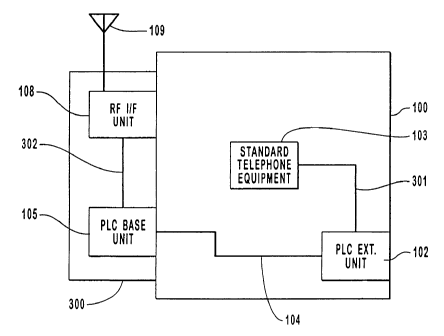
Figure 3 shows the preferred embodiment of invention depicting the
components and connections used in the distribution of wireless communication
5 signals to standard telephone equipment in this invention. An external
conversion
module 300 interfaces directly to the RF signals received from the antenna 109
to
convert the incoming signals to the standard telephone signals. The RF
signals,
including PCS, Cellular and Satellite signals, enter the invention via the
external
antenna 109 on the external conversion module 300. The preferred external
10 conversion module 300 comprises an RF Interface unit 108 and a Power Line
Carrier
(PLC) base unit 105 to interface and both send and receive signals via the
power line
104. These power line signals are received (or sent) by the extension unit 102
via the
telephone lines 301 which interface directly to the existing or standard
telephone
equipment 103. This provides system provides the capability of using and
distributing
15 the existing telephone equipment with the wireless RF incoming signals,
thereby
providing the user with the ability to receive PCS signals anywhere in the
building
100 where power outlets are available.
The described embodiment of this invention is to be considered in all respects
only as illustrative and not as restrictive. Although, this embodiment of the
invention
20 describes voice telephone equipment, it alternatively can also be applied
to electronic
(computer modem) communication. Also, although this described embodiment of
the
invention identifies the use of certain well known modulation techniques, it
is not
7
CA 02339972 2001-02-08
WO 00/10264 PCT/US99/17947
intended to be limited thereto. Rather, this invention may alternatively
employ other
similar, currently known or developed in the future, modulation techniques.
Similarly, this invention is not limited to specific components, and the
substitution of
alternative equivalent components should be considered within the scope of
this
5 invention. The scope of this invention is indicated by the appended claims
rather than
by the foregoing description. All changes which come within the meaning and
range
of equivalency of the claims are to be embraced within their scope.
8