Note: Descriptions are shown in the official language in which they were submitted.
CA 02339979 2001-02-08
WO 00/14568 PCT/US99/20281
1
SIMPLIFIED RECEIVER WITH ROTATOR FOR PERFORMING
POSITION LOCATION
BACKGROUND OF THE INVENTION
I. Field of the Invention
The present invention relates to position location. More particularly,
the present invention relates to a novel and improved method and
apparatus for performing position location in wireless communications
system.
II. Description of the Related Art
Both government regulation and consumer demand have driven the
demand for position location functionality in cellular telephones. The
global positioning system (GPS) is currently available for performing
position location using a GPS receiver in conjunction with a set of earth
orbiting satellites. It is therefore desirable to introduce GPS functionality
into a cellular telephone.
Cellular telephones, however, are extremely sensitive to cost, weight
and power consumption considerations. Thus, simply adding additional
circuitry for performing GPS location is an unsatisfactory solution for
providing position location functionality in a cellular telephone. Thus, the
present invention is directed to providing GPS functionality in a cellular
telephone system with a minimum of additional hardware, cost and power
consumption.
SUMMARY OF THE INVENTION
The present invention is a novel and improved method and
apparatus for performing position location in wireless communications
system. One embodiment comprises a method for performing position
location using a set of signals transmitted from a set of satellites including
the steps of storing coarse search data, performing a coarse search on said
coarse search data for each satellite from said set of satellites, receiving
fine
search data, performing a set of fine searches on said fine search data, each
CA 02339979 2001-02-08
WO 00/14568 PCT/US99/20281
2
fine search being performed on a different time segment of said fine search
data, and reporting results.
BRIEF DESCRIPTION OF THE DRAWINGS
The features, objects, and advantages of the present invention will
become more apparent from the detailed description set forth below when
taken in conjunction with the drawings in which like reference characters
identify correspondingly throughout and wherein:
Fig. 1 is a block diagram of the Global Positioning System (GPS)
waveform generator;
Fig. 2 is a highly simplified block diagram of a cellular telephone
system configured in accordance with the use of present invention;
Fig. 3 is a block diagram of a receiver configured in accordance with
one embodiment of the invention;
Fig. 4 is another block diagram of the receiver depicted in Fig. 3;
Fig. 5 is a receiver configured in accordance with an alternative
embodiment of the invention;
Fig. 6 is a flow chart of the steps performed during a position location
operation;
Fig. 7 is a block diagram of a DSP configured in accordance with one
embodiment of the invention;
Fig. 8 is a flow chart illustrating the steps performed during a search
performed in accordance with one embodiment of the invention;
Fig. 9 is a time line illustrating the phases over which fine and coarse
searches are performed in one embodiment of the invention;
Fig. 10 is a time line of the search process when performed i n
accordance with one embodiment of the invention;
Fig.11 is a diagram of search space.
Fig. 12 is a block diagram of a receiver in accordance with another
embodiment of the invention.
DETAILED DESCRIPTION OF THE PREFERRED
EMBODIMENTS
A novel and improved method and apparatus for performing
position location in wireless communications system is described. The
CA 02339979 2001-02-08
WO 00/14568 PCT/US99/20281
3
exemplary embodiment is described in the context of the digital cellular
telephone system. While use within this context is advantageous, different
embodiments of the invention may be incorporated in different
environments or configurations. In general, the various systems described
herein may be formed using software controlled processors, integrated
circuits, or discreet logic, however, implementation in an integrated circuit
is preferred. The data, instructions, commands, information, signals,
symbols and chips that may be referenced throughout the application are
advantageously represented by voltages, currents, electromagnetic waves,
magnetic fields or particles, optical fields or particles, or a combination
thereof. Additionally, the blocks shown in each block diagram may
represent hardware or method steps.
Fig. 1 is a block diagram of the Global Positioning System (GPS)
waveform generator. The circle with a plus sign designates modulo-2
addition. In general, the GPS constellation consists of 24 satellites: 21
space
vehicles (SVs) used for navigation and 3 spares. Each SV contains a clock
that is synchronized to GPS time by monitoring ground stations. To
determine a position and time, a GPS receiver processes the signals received
from several satellites. At least 4 satellites must be used to solve for the 4
unknowns (x, y, z, time).
Each SV transmits 2 microwave carriers: the 1575.42 MHz L1 carrier,
which carries the signals used for Standard Positioning Service (SPS), and
the 1227.60 MHz L2 carrier, which carries signals needed for Precise
Positioning Service (PPS). PPS is used by governmental agencies and allows
a higher degree of accuracy in positioning.
The L1 carrier is modulated by the Coarse Acquisition (C/A) code, a
1023-chip pseudorandom code transmitted at 1.023 Mcps that is used for civil
position location services. (The Coarse Acquisition code should not be
confused with the coarse and fine acquisitions described herein, which both
involve the use of the C/A codes.) Each satellite has its own C/A code that
repeats every lms. The P code, which is used for PPS, is a 10.23 MHz code
that is 267 days in length. The P code appears on both carriers but is 90
degrees out of phase with the C/A code on the L1 carrier. The 50Hz
navigation message, which is exclusive-ORed with both the C/A code and P
code before carrier modulation, provides system information such as
satellite orbits and clock corrections.
The L1 carrier is modulated by the Coarse Acquisition (C/A} code, a
1023-chip pseudorandom code transmitted at 1.023 Mcps that is used for civil
CA 02339979 2001-02-08
WO 00114568 PCT/US99/20281
4
position location services. Each satellite has its own C/A code that repeats
every lms. The P code, which is used for PPS, is a 10.23 MHz code that is 267
days in length. The P code appears on both carriers but is 90 degrees out of
phase with the C/A code on the L1 carrier. The 50Hz navigation message,
which is exclusive-ORed with both the C/A code and P code before carrier
modulation, provides system information such as satellite orbits and clock
corrections.
The L1 carrier is modulated by the Coarse Acquisition (C/A) code, a
1023-chip pseudorandom code transmitted at 1.023 Mcps that is used for civil
position location services. Each satellite has its own C/A code that repeats
every lms. The P code, which is used for PPS, is a 10.23 MHz code that is 267
days in length. The P code appears on both carriers but is 90 degrees out of
phase with the C/A code on the L1 carrier. The 50Hz navigation message,
which is exclusive-ORed with both the C/A code and P code before carrier
modulation, provides system information such as satellite orbits and clock
corrections.
Each satellite has a different C/A code that belongs to a family of codes
called Gold codes. Gold codes are used because the cross-correlation between
them are small. The C/A code is generated using two 10-stage shift registers
as shown below in figure 1.4-2. The G1 generator uses the polynomial
1+X3+X'°, while the G2 generator uses the polynomial
1+XZ+X'+X6+X8+Xy+X'°. The C/A code is generated by exclusive ORing the
output of the G1 shift register with 2 bits of the G2 shift register.
Fig. 2 is a highly simplified block diagram of a cellular telephone
system configured in accordance with the use of present invention. Mobile
telephones 10 are located among base stations 12, which are coupled to base
station controller (BSC) 14. Mobile switching center MSC 16 connects BSC 14
to the public switch telephone network (PSTN). During operation, some
mobile telephones are conducting telephone calls by interfacing with base
stations 12 while others are in standby mode.
As described in copending US patent application serial no. 09/040,051
entitled "SYSTEM AND METHOD FOR DETERMINING THE POSITION OF
A WIRELESS CDMA TRANCEIVER" assigned to the assignee of the present
invention and incorporated herein by reference, position location is
facilitated by the transmission of a position request message containing
"aiding information" that allows the mobile telephone to quickly acquire
the GPS signal. This information includes the ID number of tile SV (SV ID),
the estimated code phase, the search window size around the estimate code
CA 02339979 2001-02-08
WO 00/14568 PCT/US99/20281
phase, and the estimated frequency Doppler. Using this information, the
mobile unit can acquire the GPS signals and determine its location more
quickly.
In response to the aiding message, the mobile unit tunes to the GPS
5 frequency and begins correlating the received signal with its locally
generated C/A sequences for the SVs indicated by the base station. It uses
the aiding information to narrow the search space and compensate for
Doppler effects, and obtains pseudo-ranges for each satellite using time
correlation. Note that these pseudo-ranges are based on mobile unit time
(referenced from the CDMA receiver's combiner system time Gaunter),
which is a delayed version of GPS time.
Once this information is calculated, the mobile unit sends the
pseudo-ranges for each satellite (preferably to 1/8 chip resolution) and the
time the measurements were taken to the base station. The mobile unit
then retunes to CDMA to continue the call.
Upon, receipt of the information, the BSC uses the one-way delay
estimate to converts the pseudo-ranges from mobile unit time to base
statian time and computes the estimated position of the mobile unit by
solving for the intersection of several spheres.
Another parameter provided by the aiding message is the frequency
Doppler or Doppler offset. The Doppler effect manifests as an apparent
change in the frequency of a received signal due to a relative velocity
between the transmitter and receiver. The effect of the Doppler on the
carrier is referred to as frequency Doppler, while the effect on the baseband
signal is referred to as code Doppler.
In the GPS case, frequency Dappler changes the received carrier
frequency so the effect is the same as demodulating with a carrier offset.
Since the base station's GPS receiver is actively tracking the desired
satellite,
it knows the frequency Doppler due to satellite movement. Moreover, the
satellite is so far away from the base station and the mobile unit that the
Doppler seen by the mobile unit is effectively the same as the Doppler seen
by the base station. In one embodiment of the invention, to correct for the
frequency Doppler value, the mobile unit uses a rotator in the receiver. The
frequency Doppler ranges from --4500Hz to +4500Hz, and the rate of change
is on the order of 1 Hz/s.
The effect of the code Dappler is to change the 1.023Mhz chip rate,
which effectively compresses or expands the width of the received C/A code
chips. In one embodiment of the invention, the mobile unit correct for code
CA 02339979 2001-02-08
WO 00/14568 PCT/US99/20281
6
Doppler by multiplying the frequency Doppler by the ratio 1.023/1575.42.
The mobile unit can then correct for code Doppler over time by dewing
(introducing delay into) the phase of the received IQ samples in 1/16 chip
increments as necessary.
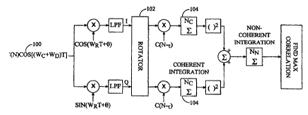
Fig. 3 is a block diagram of the receiver portion of a cellular telephone
(wireless subscriber unit) configured in accordance with one embodiment of
the invention. The received waveform 100 is modeled as the C/A signal
c(n) modulated with a carrier at frequency w~ + w~, where w~ is the nominal
carrier frequency 1575.42 MHz, and wd is the Doppler frequency created by
satellite movement. The Doppler frequency ranges from 0 when the
satellite is directly overhead, to about 4.5kHz in the worst case. The
receiver
analog section can be modeled as demodulation with a carrier at frequency
wr and random phase _, followed by low pass filtering.
The resulting baseband signal is passed through an A/D converter
(not shown) to produce digital I and Q samples, which are stored so that they
may be repeatedly searched. The samples are generated at two times the
C/A code chip rate (chipx2) which is a lower resolution than necessary to
perform the fine search algorithm, but which allows 18 ms of sample data to
be stored in a reasonable amount of memory. In general, it is desirable to
perform the searching over something greater than l0ms in order to allow
acquisition in most environmental conditions, with l8ms being a preferred
integration period. These environmental conditions include being inside or
not having a direct view to the satellite.
During operation, the samples are first rotated by rotator 102 to
correct for the Doppler frequency offset. The rotated I and Q samples are
correlated with various offsets of the satellite's C/A sequence and the
resulting products are coherently integrated over Nc chips by integrators 104.
The coherent integration sums are squared and added together to remove
the effect of the unknown phase offset _. To augment the hypothesis test for
a particular offset, several coherent intervals are non-coherently combined.
This despreading is performed repeatedly at various time offsets to find the
time offset of the satellite signal. Rotator 102 removes the frequency Doppler
created by satellite movement. It uses the Doppler frequency specified by the
base station (preferably quantized to lOHz intervals) and rotates the I and Q
samples to remove the frequency offset.
In one embodiment of the invention, the rotation is continuous only
over the coherent integration window. That is, the rotator stops in between
CA 02339979 2001-02-08
WO 00/14568 PCT/US99/20281
7
coherent integration periods of, for example, 1 ms. Any resulting phase
difference is eliminated by the square and sum.
Fig. 4 is another block diagram of a receiver configured in accordance
with one embodiment of the invention, where the rotator portion of the
receiver is depicted in greater detail.
Fig. 5 is a receiver configured in accordance with an alternative
embodiment of the invention. This internal embodiment of the invention
takes advantage of the ability to stop the rotator between coherent
integration periods by rotating the locally generated C/A sequence instead of
the input samples.
As shown, the C/A sequence c(n) are rotated by application to the
sinusoids sin(WanT~) and cos(W~nT~) and then stored. The rotation of the
C/A sequence only needs to be done once for each satellite. Thus, rotating
the C/A sequence reduces the amount of computation required. It also
saves memory in the DSP used to perform this computation in one
embodiment of the invention.
Another significant impairment that degrades the performance of the
position location algorithm is the frequency error in the mobile units
internal clock. It is this frequency error which drives the use of short
coherent integration times on the order of 1 ms. It is preferable to perform
coherent integration over longer time periods.
In an exemplary configurations, the mobile's free running (internal)
local oscillator clock is a 19.b8MHz crystal that has a frequency tolerance of
+/-5ppm. This can cause large errors on the order of +/- 7500 Hz. This clock
is used to generate the carriers used for demodulation of the GPS signals, so
the clock error will add to the signal acquisition time. Because the time
available to search is very small, error of this magnitude due to the
frequency tolerance are not tolerable and must be greatly reduced.
To allow longer coherent integration times, in one embodiment of
the invention, the CDMA receiver corrects for local oscillator error by using
timing acquired from the CDMA pilot, or any other source of timing
information available. This produces a control signal that is used to tune the
local oscillator clock to 19.68MHz as closely as possible. The control signal
applied to the local oscillator clock is frozen when the RF unit switches from
CDMA to GPS.
Even after the correction is performed using the timing information from
the bases station (or other source), however, some additional clock error
remains. In one embodiment of the invention, the resulting frequency
CA 02339979 2001-02-08
WO 00/14568 PCTNS99/20281
8
uncertainty after correction is +/- 100Hz. This remaining error still reduces
the performance of the receiver, and in general prevents longer coherent
integration times. In one embodiment of the invention, the remaining
error simply avoided by performing non-coherent integration for duration
of more than 1ms which reduces performance.
As also shown in Fig. 1, the 50Hz NAV/system data is also modulated
onto the L2 carrier. If a data transition (0 to 1 or 1 to 0) occurs between
the
two halves of a coherent integration window, the resulting coherent
integration sum will be zero because the two halves will cancel each other
out. This effectively reduces the number of non-coherent accumulations by
one in the worst case. Although the data boundaries of all the satellites are
synchronized, they do not arrive at the mobile unit simultaneously because
of the differences in path delay. This path delay effectively randomizes the
received data phase.
In one embodiment of the invention, the problem of different data
phases on different signals is to include the data phase in the aiding
information sent from the base station to the mobile unit. Since the base
station is demodulating the 50Hz data, it knows when the data transitions
occur for each satellite. By using knowledge of the one-way delay, the base
station can encode the data phase in, for example, 5 bits (per satellite) by
indicating which one millisecond interval (out of 20) the data transition
occurs on.
If the coherent integration window straddles the 50Hz data boundary the
coherent integration is divided into two (2) sections. One section preceding
the data boundary and one section following the data boundary. For
example, if Enl is the coherent integration sum over the window preceding
the data boundary the first half of this window and En2 is the coherent
integration sum over the window following the data boundary, the mobile
unit then selects the maximum (in magnitude) of (En1 + En2) (in case the
data stayed the same) and (Enl - En2) (in case the data changed) to account
for the phase change. The mobile unit also has the option of performing
non-coherent combining of the two halves over this data window or
avoiding this data window completely.
In an alternative embodiment of the invention, the mobile unit
attempts to find the data transitions without the aiding information from
the base station by comparing the magnitude squared of the suJn and
difference in 1 ms coherent integration.
CA 02339979 2001-02-08
WO 00/14568 PCT/US99/20281
9
In one embodiment of the invention, a firmware-based DSP (Digital
Signal Processor) approach is used to perform the GPS processing. The DSP
receives I and Q samples at a chipx2 (2.046 MHz) or chipx8 (8.184 MHz) rate,
and stores a snapshot of 4-bit I and Q samples in its internal RAM.
In the exemplary embodiment, the DSP generates the C/A sequence,
performs rotation to eliminate frequency Doppler, and correlates over the
search window provided by the base station for each of the satellites. The
DSP performs coherent integration and non-coherent combining and slews
an IQ sample decimator as necessary to compensate for code Doppler.
To save computation and memory, the initial search is performed
using - chip resolution and a finer search to obtain 1/8 chip (higher)
resolution is performed around the best index (or indexes). System time is
maintained by counting hardware-generated 1ms interrupts (derived from
local oscillator).
Additionally, in one embodiment of the invention, the fine search is
performed by accumulating the chipx8 samples (higher resolution) over the
duration of one chip at various chipx8 offsets. The correlation codes are
applied to the accumulated values yielding correlation values that vary with
the particular chipx8 offset. This allows the code offset to be determined
with chipx8 resolution.
Fig. 6 is a flow chart illustrating the steps performed to correct for the
local oscillator error during a position location procedure when performed
in accordance with one embodiment of the invention. At step 500, it is
determined whether the local oscillator has been corrected recently. If not,
then the pilot is acquired from the base station, and error of the local
oscillator is determined by comparing to the pilot timing at step 502 and a
correction signal generated based on that error.
The flow then leads to step 504, where the correction signal is frozen
at the current value. At step 506, enters GPS mode and performs the
position location using the corrected clock. Once the position location has
been performed, the mobile unit leaves GPS mode at step 508.
Fig. 7 is an illustration of a DSP receiver system configured i n
accordance with one embodiment of the invention. The DSP performs the
entire searching operation with minimal additional hardware. DSP core
308, modem 306, interface unit 300, ROM 302 and Memory (RAM} 304 are
coupled via bus 306. Interface unit 300 receives RF samples from an RF unit
(not shown) and provides the samples to RAM 304. The RF samples can be
stored at coarse resolution or fine resolution. The DSP care 308 processes
CA 02339979 2001-02-08
WO 00/14568 PCTNS99/20281
the samples stored in memory using instruction stored in ROM 302 as well
as in memory 304. Memory 304 may have multiple "banks" some of which
store samples and some of which store instructions. Modem 700 performs
CDMA processing during normal mode.
5 Fig. 8 is a flow chart of the steps performed during a position location
operation. A position location operation begins when the aiding messing is
received, and the RF systems is switched to GPS frequencies at step 600.
When the RF is switched to receive GPS, the frequency tracking loop is
fixed. The DSP receives aiding information from the phone microprocessor
10 and sorts the satellites by Doppler magnitude.
At step 602, the coarse search data is stored within the DSP RAM. The
DSP receives a few hundred microseconds of input data to set an Rx AGC.
The DSP records the system time and begins storing an l8ms window (DSP
memory limitation) of chipx2 IQ data in its internal RAM. A contiguous
window of data is used to mitigate the effects of code Doppler.
Once the data is stored, a coarse search is performed at step 604. The
DSP begins the coarse (chipx2 resolution) search. For each satellite, the DSP
generates the C/A code, rotates the code based on the frequency Doppler, and
correlates over the search window specified by the base station, via repeated
application of the C/A code to the stored coarse search data. Satellites are
processed over the same l8ms data window and the best chipx2 hypothesis
that exceeds a threshold is obtained for each satellite. Although a 2ms
coherent integration time (with 9 non-coherent integrations) is used in one
embodiment of the invention, longer coherent integration times can be
used (for example l8ms), although preferably where additional adjustments
are made as described below.
Once the coarse search is performed, a fine search is conducted, at step
606. Before beginning the fine search, the DSP computes the rotated C/A
code for each of the satellites. This allows the DSP to process the fine
search
in real-time. In performing the fine (chipx8 resolution) search, the
satellites
are processed one at a time over different data.
The DSP first stews the decimator to compensate for code Doppler for
the given satellite(s). It also resets the Rx AGC value while waiting for the
next lms boundary before storing a 1ms coherent integration window of
chipx8 samples.
The DSP processes 5 contiguous chipx8 resolution hypotheses on this
1ms coherent integration window, where the center hypothesis is the best
hypothesis obtained in the coarse search. After processing the next 1ms
CA 02339979 2001-02-08
WO 00/14568 PCT/US99/20281
11
window, the results are combined coherently and this 2ms sum is combined
non-coherently for all Nn iterations.
This step (starting from stewing the decimator) is repeated on the
same data for the next satellite until all the satellites have been processed.
If
the code Doppler for 2 satellites is similar in magnitude, it may be possible
to
process both satellites over the same data to reduce the number of required
data sets. In the worst case, 8 sets of 2*Nn data windows of 1ms are used for
the fine search.
Finally, at step 608, the results are reported to the microprocessor and
the vocoder process is restarted within the DSP so that the call can continue.
The DSP reports pseudoranges to the microprocessor, which forwards them
to the base station. After the microprocessor redownloads the vocoder
program code into the DSP memory, the DSP clears its data memory and
restarts the vocoder.
Fig. 9 is a diagram illustrating the fine search performed after the
coarse search. After isolating the best chipx2 phase in the coarse search, the
DSP performs a fine search around this phase to gain chipx8 resolution.
The 5 phases to compare in the fine search are shown enclosed by a
rectangle. The best chipx2 phase is evaluated again so that comparisons can
be made over the same set of data. This also allows the coarse search and
fine search to use different integration times. The fine search is performed
separately for each satellite because each satellite may have a different
value
for code Doppler.
Fig.10 provides a time line of the search process when performed i n
accordance with one embodiment of the invention. The overall processing
time (coarse + fine search) is performed in about 1.324 seconds in one
embodiment of the invention, which does interrupt the call, but still allows
the call to continue once the search is performed. The total search time of
1.324 seconds is an upper bound, because it assumes that the DSP needs to
search all 8 satellites and each satellite has a search window of 68 chips.
The
probability that the entire 1.324 seconds will be necessary is small, however,
due to the geometry of the satellite orbits.
During the first l8ms 80, IQ sample data is collected at the GPS
frequency. During the period 82, a coarse search is performed internally
which could last up to 1.13 seconds, but which will probably terminate early
when the satellite signals are identified. Once the coarse search is
performed, the C/A codes are computed during time period 84, which takes
24 ms. During time periods 86 the slew value is adjusted for code Doppler
CA 02339979 2001-02-08
WO 00/14568 PCT/US99I20281
12
and the Rx AGC is further adjusted. During time periods 88, fine searches
are performed on the IQ data samples, with continuous adjustment
performed during time periods 86. The use of 18 ms integration times
allows code Doppler to be neglected because the received C/A code phase
will be shifted by less than 1/16 of a chip. Up to eight sequences of
adjustments and fine searches are performed for the up to eight satellites, at
which time the position location procedure is complete.
Additionally, in some embodiments of the invention, the phone
continues to transmit reverse link frames to the base station while the
position location procedure is performed. These frames may contain null
information simply to allow the base station to remain synchronized with
the subscriber unit, or the frames may contain additional information such
as power control commands or information request. The transmission of
these frames is preferably performed when GPS samples are not being
gathered when the RF circuitry is available, or while the GPS samples are
gathered if sufficient RF circuitry is available.
Although the use of l8ms integration time avoids the effects of code
Doppler, the transmission of data over the GPS signals at 50Hz rate can
cause problems if a data change occurs within the l8ms processing span (as
described above). The data change causes the phase of the signal to shift.
The 50Hz data boundaries occur at different places for each satellite. The
phase of the 50Hz transitions for each satellite have been effectively
randomized by the varying path lengths from each satellite to the phone.
In the worst case, if the data bit was inverted in the middle of a
coherent integration interval, the coherent integration could be completely
wiped out. For this reason, in an alternative embodiment of the invention,
the base station must communicate the data transition boundaries for each
satellite to the phone (also described above). Preferably, the data
transmission boundary is also included in the aiding message transmitted
from the base station (such as in a set of five bit messages indicating the
millisecond interval during which the transition occurs for each satellite).
The phone uses this boundary to split the coherent integration interval for
each satellite into 2 pieces and decide whether to add or subtract the
coherent integration sums in these 2 intervals. Thus, by also including the
data boundary of each GPS signal, the reliability of the location procedure is
increased.
In the exemplary embodiment of the invention, any frequency
uncertainty creates a loss in Ec/Nt that increases with the coherent
CA 02339979 2001-02-08
WO 00/14568 PCT/US99/20281
13
integration time. For example, uncertainty of +/-100Hz, the loss in Ec/Nt
increases rapidly as the coherent integration time is increased, as shown in
Table I.
Nc Loss in Ec/Nt
1023 (1ms) 0.14 dB
2046 (2ms) 0.58 dB
4092 (4ms) 2.42 dB
6138 (6ms) 5.94 dB
8184 (8ms) 12.6 dB
Table I.
As also noted above, there is always some unknown frequency offset
of the local oscillator in the mobile unit. It is this unknawn frequency
offset
that prevents longer coherent despreading and integration from being
performed. Longer coherent would improve processing if the effects of the
unknown frequency offset could be reduced.
In one embodiment of the invention, this unknown frequency offset
is accounted for by expanding the search space to 2 dimensions to include
frequency searches. For each hypothesis, several frequency searches are
performed, where each frequency search assumes the frequency offset is a
known value. By spacing the frequency offsets, one can reduce the
frequency uncertainty to an arbitrarily small value at the expense of added
computation and memory. For example, if 5 frequency hypotheses are used,
the resulting search space is shown in Fig. 10.
For a +/-100Hz frequency uncertainty, which is the typically operating
specification of a mobile unit, this configuration reduces the maximum
frequency offset to 20Hz (one hypothesis must be within 20Hz of the actual
frequency offset). With a 20ms coherent integration time, the loss in Ec/Nt
with a 20Hz frequency offset is 2.42 dB. By doubling the number of
frequency hypotheses to 10, the frequency uncertainty can be reduced to
lOHz, which causes an Ec/Nt loss of .58dB. However, adding additional
hypotheses widens the search space, which increases both the computation
and memory requirements.
One embodiment of the invention computes the frequency
hypothesis by lumping the frequency offset in with the frequency Doppler,
CA 02339979 2001-02-08
WO 00/14568 PCT/US99/20281
14
and computing a new rotated PN code for each frequency hypothesis.
However, this makes the number of frequency hypotheses a multiplicative
factor in the total computation: 5 frequency hypotheses would mean 5 times
as much computation.
Alternatively, since the frequency uncertainty is small compared to
the frequency Doppler, the rotation phase can be considered to be constant
over a 1ms interval (8% of a period for an 80Hz hypothesis) in another
embodiment of the invention. Therefore, by dividing the coherent
integration interval up into lms subintervals, the integration sums of the
subintervals are rotated to reduce the added computations needed to
compute the frequency searches by three orders of magnitude. The result is
that longer coherent despreading can be performed, and performance
improved.
Fig.12 is a block diagram of a receiver configured in accordance with
the use of longer coherent despreading approach. The first set of multipliers
50 compensates for the frequency Doppler by correlating the IQ
samples with a rotated C/A code. This is equivalent to rotating the IQ
samples before correlation with the unmodified C/A code. Since the
frequency Doppler can be as large as 4500Hz, the rotation is applied to every
chip. After coherently integrating over a 1ms interval (1023 chips) using
accumulators 52, the second set of multipliers 54 rotates the 1ms integration
sums (~ and ~,) to implement the frequency hypothesis. The rotated sums
are then added over the whole coherent integration interval.
Recall that the frequency Doppler rotation was only computed o n
1023 chips to save memory and computation. For coherent integration
times longer than lms, each coherent integration sum are multiplied by a
phase offset to make the phase of the rotation continuous over time. To
show this mathematically, the 1ms coherent integration sum with
frequency Doppler rotation can be expressed as:
SI = ~ ~I(n)+ jQ(n)~(n)e-~'"~"'~ with ~ = Re{ S, } and ~= Im{ S, }
n=I
where I(n) and Q(n) are the input samples received on the I and Q
channels respectively, c(n) is the unrotated C/A code, wd is the frequency
Doppler, and T~ is the chip interval (.9775us). A 2ms coherent integration
sum can be expressed as:
2046
S(2ms) _ ~ ~I(n) + JQ(n)~(n)e 'W~nr
n=I
CA 02339979 2001-02-08
WO 00/14568 PCT/US99/20281
1023 1023
_ ~, ~I(n)-~- jQ(n)~(n)e ~"''n'' + e-j".rtloz3)r ~ ~j(~ + 1023) + jQ(n+
1023)~(n)~ Jw~n
n=1 n-_1
= S + g-~"~~(1023)T ~.
I 2
Here, S1 is the first 1ms integration sum and Sz is the second 1ms
5 integration sum computed using the same rotated C/A values that were
used to compute S,. The term a l"'dn023)Tc iS the phase offset that
compensates
for using the same rotated values. Similarly, a 3ms coherent integration
sum can be expressed as
S(3ms) - SI + e-jwrtloz3)r Sz + e-j":rtzoa6)T S3
10 So to extend the integration time while using the same 1023-element
rotated C/A sequence, the (n+1) 1ms integration sum should be multiplied
by e-'""'"(1"") before being added to the whole sum. Since this is a rotation
of
1rns integration sums, we can combine this operation with the frequency
search to avoid having to perform 2 rotations. That is, since
15 e-lw,,n(Inrc)e-jw,,n(Ims) - e-~(w,,+w,,)n(Ims)
we can multiply the (n+1)th 1ms integration sum by e'("'''+"~h)n(1~"~) to
search a frequency hypothesis and account for the frequency Doppler phase
offset.
Note that the frequency search can be reduced after acquiring one
satellite, because the frequency uncertainty is not dependent on the
satellite.
A much finer frequency search can be performed if a longer coherent
integration is desired.
In the exemplary embodiment of the invention, the fine search is
performed in similar manner the coarse search with 2 differences. First, the
integration intervals are always added coherently instead of squaring and
adding noncoherently. Second, the rotation to remove the frequency
uncertainty (which should be known after the coarse search) is combined
with the frequency Doppler phase offset and used to rotate the 1ms coherent
integration intervals before adding them together.
In an alternative embodiment of the invention, the coherent
integration window of chipx2 data is integrated for integration times longer
than l8ms. This embodiment is useful were additional memory is
available. For coherent integrations longer than l8ms, the 50Hz data
boundaries are treated the same as with shorter integration periods. The
base station indicates where the boundaries are for each satellite and the DSP
CA 02339979 2001-02-08
WO 00/14568 PCT/US99/20281
16
decides whether to add or subtract the sum of 20 1ms coherent integration
intervals to or from its running sum.
However, because the product of the frequency uncertainty and the
integration time constant affects the loss in Ec/Nt, the frequency uncertainty
must be reduced to very small levels for long coherent integration intervals.
Since a 20ms integration with a 20Hz frequency uncertainty resulted in a
loss in Ec/Nt of 2.42 dB, maintaining the same loss with an integration time
of 400ms requires that the frequency uncertainty be reduced to lHz. To
correct for this problem, the frequency uncertainty is reduced down to 1Hz
in a hierarchical manner. For example, a first frequency search reduces the
uncertainty from 100Hz to 20Hz, a second search reduces the uncertainty to 4
Hz, and a third search reduces the uncertainty to lHz. The frequency search
will also compensate for errors in the frequency Doppler obtained from the
base station.
Additionally, to perform longer integrations only satellites with
similar Doppler are searched over the same data for long integration times,
since the code Doppler is different for each satellite. The DSP computes how
long it takes to slip 1/16 of a chip and stews the decimator as it collects a
coherent integration data window. Additionally, multiple data windows
are taken in this embodiment.
Thus, a method and apparatus for performing position location in
wireless communications system has been described. The previous
description of the preferred embodiments is provided to enable any person
skilled in the art to make or use the present invention. The various
modifications to these embodiments will be readily apparent to those skilled
in the art, and the generic principles defined herein may be applied to other
embodiments without the use of the inventive faculty. Thus, the present
invention is not intended to be limited to the embodiments shown herein
but is to be accorded the widest scope consistent with the principles and
novel features disclosed herein.
WHAT IS CLAIMED IS: