Note: Descriptions are shown in the official language in which they were submitted.
CA 02340000 2001-02-08
WO 00/09433 PCTlFI99/00644
1
Method and device for transferring a web onto a reel spool in the reel-
up of a paper web
The invention relates to a method for transferring a web in the reel-up
of a paper web as presented in the preamble of the appended claim 1.
The invention relates also to a device intended for applying the method,
which is of the type presented in the preamble of the appended claim 5.
A reel change in the reel-up of a paper web is made in a known manner
by cutting the web traveling to an old reel being completed and by
guiding the web around a new reel spool previously brought into
contact with the web and forming the core for a new reel. For
performing the cutting and for guiding the web around the new reel
spool, air blows are generally used, wherein mechanical cutting of the
web in part or in full width can be used as an aid. With thin paper
grades, a blow from below the web or from the side of the web is often
sufficient to penetrate and cut the web.
The above-described measures are taken during the run when a con-
tinuous paper web coming from preceding machine sections is being
reeled up, wherein the change sequence is performed each time the
reel is completed. Before starting the run with said repeated reel
changes, the paper web must be transferred for the first time around an
empty reel spool in a so-called turn-up blow. Before the turn-up blow,
the web is run in its full width through the reeling cylinder to the pulper.
The turn-up blow is executed with an overlying blowing device, a so-
called gooseneck, which is brought by a suitable turning mechanism
from above down in such a way that the blow nozzle points at the
surface of the reeling cylinder, on top of which the web is running to the
pulper. The gooseneck is brought to the operating position in such a
way that the nozzle points at the surface of the reeling cylinder after a
nip between the empty reel spool and the reeling cylinder. The web on
the reeling cylinder is torn by the air blow, and air is guided under the
web to lift the web to wind up around the empty reel spool. On both
sides of the tearing point, the web is torn to the edges, and the new
leading end of the web follows the reel spool.
CA 02340000 2001-02-08
WO 00/09433 PCT/FI99/00644
2
The gooseneck used as the turn-up blow device is relatively complex
and requires several pivotal movements, a pressurized air container of
its own and its respective valves. Moreover, the gooseneck with its
turning mechanisms require space above the reeling cylinder.
It is an aim of the present invention to eliminate the above-mentioned
drawbacks and to present a novel method for transferring the web onto
the reel spool by the so-called turn-up blow. It is an aim of the method
to replace the gooseneck which has been previously used as the turn-
up blow device. It is another aim of the invention to make the space
utilization in the reel-up more efficient. It is also an aim of the invention
to make it possible to select the location of the reel spool more freely in
the turn-up blow, because the gooseneck has previously determined
the location of the reel spool at least in the respect that the reel spool
must have been in a sufficiently high position for the gooseneck to
reach around it down below it. For achieving this aim, the method
according to the invention is primarily characterized in what will be
presented in the characterizing part of the appended claim 1. The
transfer is effected in the invention by an air blow brought from below.
Thus, the air blow pipes can be placed in the same structure in which
change blow pipes are normally used during reel change sequences. In
other respects, the transfer of the web can be fully effected by the
same principles and the same auxiliary methods.
It is also an aim of the invention to present a device for transferring the
web onto the reel spool. For achieving this aim, the device according to
the invention is primarily characterized in what will be presented in the
characterizing part of the appended claim 5. The air channel for
effecting the turn-up blow is brought from below to an operative
connection with the reeling cylinder. The air channel can be placed in
the same structure as the change blow pipes, wherein one or several
change blow pipes can be replaced with one or several turn-up blow
pipes, respectively, or turn-up blow pipes can be added next to existing
change blow pipes. It is also possible to use the same change blow
pipes, turnable to a different position than in the change situation, as
turn-up blow pipes.
CA 02340000 2001-02-08
WO 00/09433 PCT/FI99/00644
3
In the following, the invention will be described in more detail with
reference to the appended drawings, in which
Fig. 1 shows a reel-up comprising a turn-up blow device in a side
view,
Fig.2 shows a turn-up blow device according to a preferred
embodiment, and
Fig. 3 shows a turn-up blow device according to another preferred
embodiment.
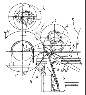
Figure 1 shows a part of the reel-up for a paper web, namely a reeling
cylinder 1 which guides the continuous paper web W', which comes
from previous machine sections at the end of the paper machine or an
after-treatment machine for paper and normally has a width of several
metres, to a reel spool. The reeling takes place in a way known as such
so that the reeling cylinder 1 is in contact with the reel spool via a
reeling nip. The reel spool is loaded towards the reeling cylinder by a
loading mechanism known as such, and at the same time a reel spool
forming the core of the reel is supported in a suitable support structure,
such as on reeling rails 3.' The reel-up is designed to operate
continuously to reel successive paper reels around successive reel
spools brought to the reeling position. The full machine reels have
typically a weight exceeding 10 tonnes.
Figure 1 shows a situation in which the web W indicated with an un-
broken line is not yet reeled up on a reel to form a so-called machine
reel, but it travels in a certain sector on the reeling cylinder 1 and is
disengaged from the same as a full-width web to form broke. The figure
shows how the web falls from the reeling cylinder down to the pulper.
Letter S indicates a pulper shield located in the transverse direction
across the width of the web and limiting the inlet opening of the pulper
after the opening when seen in the longitudinal direction of the
machine. This situation is in the reel-up e.g. after threading, in which a
lead-in strip or tail is first brought through the nip between the reefing
CA 02340000 2001-02-08
WO 00/09433 PCT/FI99/00644
4
cylinder 1 and a still empty reel spool 2 to travel down to the pulper,
after which the web is spread to its full width by diagonal cutting in the
preceding machine sections.
Figure 1 shows, by a line of dots and dashes, several possible locations
of the reel spool 2 on the perimeter of the reeling cylinder 1. The empty
reel spool 2 can be brought to a position which makes it possible to
transfer the web. The reel spool is in this position at a suitable location
on the circumference of the reeling cylinder 1 in contact with the web W
travelling on the reeling cylinder 1. In principle, the transfer by the turn-
up blow onto the reel spool2 can be made at any location on the
perimeter of the reeling cylinder, but with respect to the invention, it is
preferably made when this contact point, i.e. the nip between the reel
spool 2 and the reeling cylinder 1, is at an angular distance of 0 to
90°
against the rotating direction of the reeling cylinder from the horizontal
plane passing through the central axis of the reeling cylinder. The web
must thus wrap around the reeling cylinder sufficiently to maintain the
web tension.
An air channel, i.e. a turn-up blow pipe 4, is introduced in an inclined
position from below said horizontal plane towards the reeling cylinder.
This blow pipe extends approximately towards the nip between the
reefing cylinder 1 and the empty reel spool 2. At the end of the blow
pipe there is a curve which turns the direction of the blow pipe more
towards the reeling cylinder 1, and at the outermost end of the pipe
there is a nozzle structure 4a directed towards the mantle surface of the
reeling cylinder 1. The nozzle opening of the nozzle structure is located
sufficiently close to the reeling cylinder 1 and the empty reel spool 2 in
the opening gap therebetween in a space which is limited by the mantle
of the reeling cylinder 1, by the mantle of the empty reel spool 2 and, in
the introducing direction of the blow pipe, by the common tangent of the
mantle surfaces of the reeling cylinder 1 and the reel spool 2. The
figure shows a situation in which the empty reel spool 2 is located at an
angle distance of ca. 25° from the horizontal plane. The turn-up blow
pipe 4 is placed in such a way that the nozzle opening of the nozzle
structure 4a is directed against the direction of the web W running on
the surface of the reeling cylinder after said nip so that the blow from
CA 02340000 2001-02-08
WO 00/09433 PCT/FI99/00644
the opening (arrow) is approximately parallel to the tangent of the
reeling cylinder sector extending between the nip and the mantle point
closest to the nozzle opening. The air blow strips the web W off the
surface of the reeling cylinder and guides it around the empty reel
5 spool 2. The principle of threading is thus the same as in gooseneck
threading, but the significant difference Pies in that the gooseneck does
not need to be brought from above but it is possible to use a turn-up
blow pipe brought from below and having a simpler structure and
simpler movements. Consequently, the reel-up shown in the drawing
can thus totally exclude a gooseneck as a threading device to be turned
from above down. A rigid turn-up blow pipe 4 acts simultaneously as an
air channel and a support structure for the nozzle structure 4a.
Another difference to previous transfer situations in the situation shown
by the drawing is that it is advantageous to apply the turn-up blow when
the nip between the reel spool and the reeling cylinder is relatively
close to the horizontal plane, e.g. advantageously at an angular dis-
tance of less than 45°, preferably less than 30°, from the
horizontal
plane. In the situation shown in the figure, the angular distance a is ca.
25° However, the invention is not limited to the position in which the
transfer is made. If the turn-up blow pipe 4 is arranged to have such a
structure that the nozzle structure 4a can be lifted from below to a suf-
ficiently high position, the transfer can, in principle, be made also in the
upper position shown by broken lines in the drawing, wherein the angu-
lar distance ~i is approximately 80°. The location of the end of the
blow
pipe in this situation is indicated with broken lines.
Structurally, the invention can be implemented by fixing the turn-up
blow pipe 4 at the same location where the known change blow pipes
for effecting the change blow from below are fixed. These change blow
pipes are indicated in the figure by reference numerals 5 and the nozzle
structures at their ends with the reference numeral5a. An arrow
indicates the change blow which comes from the nozzle openings of
the nozzle structures of the change blow pipes and is directed in the
direction of rotation of the surface of the reel spool towards the run of
the web W disengaging from the reel spool.
CA 02340000 2001-02-08
WO 00/09433 PCT/FI99/00644
6
The turn-up blow pipes 4 can thus be fixed on the opposite side of the
pulper shield S, seen from the pulper opening, that is, in the same
structure with the change blow pipes 5. Thus, they can be similarly
arranged to be pivoted from below up into a functional position, the
plane of pivotal movement being located in the transverse direction of
the machine and being at the same time inclined towards the reeling
cylinder. There can be one or more turn-up blow pipes 4 spaced from
each other in the transverse direction of the machine, wherein they
operate on one or several locations in the width direction of the web,
respectively. Similarly, part of the change blow pipes 5 can be replaced
by turn-up blow pipes 4 to be placed in the same location, or one or
several turn-up blow pipes 4 are placed in suitable locations next to
already existing change blow pipes 5. The change blow pipes and one
or several turn-up blow pipes can be coupled to the same source of
pressurized air.
Also the idea that the turn-up blow pipe 4 can be used as a change
blow pipe 5 falls within the scope of the invention. Thus, the nozzle
structure 4a at the end must be turnable in such a way that instead of
pointing to the reeling cylinder it points to the approximately opposite
direction, i.e. towards the run of the web disengaging from the mantle of
the empty reel spoof 2 after having travelled thereon in a short sector.
This can be effected by arranging the turn-up blow pipe rotatable
around its longitudinal axis so that the direction of the nozzle structure
at its end and consequently the direction of blow is changed. It is also
advantageous that the position of the nozzle structure at the end can
be changed so that the air blow from the nozzle opening is directed
optimally with respect to the run of the web. Consequently, the end of a
conventional pipe is preferably arranged to be flexible, wherein it is
possible to change the direction of the nozzle structure 4a and,
correspondingly, the direction of the nozzle opening. Using such a turn-
up blow pipe, it is also easier to effect the transfer irrespective of the
position of the empty reel spool2 on the perimeter of the reeling
cylinder 1, as in the upper position of Fig. 1.
Naturally, there are several alternative structures for the turn-up blow
pipe 4. It can be arranged to be adjustable in its length, wherein its
CA 02340000 2001-02-08
WO 00/09433 PCT/FI99/00644
7
height position can be adjusted according to the transfer location.
Similarly, the distance of the nozzle structure 4a from the mantle of the
reeling cylinder 1 may be adjustable e.g. in such a way that part of the
blow pipe or the whole blow pipe is slightly pivotable in the machine
direction. For this purpose, the end of the blow pipe can be arranged
flexible in the above-described manner. Thus, it is possible to adjust the
blowing direction so that the blow is directed at a desired acute angle to
the tangent of the reeling cylinder against the rotating direction of the
reeling cylinder towards the mantle of the reeling cylinder in the area
following the nip. The blow direction is selected so that the blow is
directed at a suitable angle under the web, lifting the web off the reeling
cylinder.
Naturally, it is possible to use several auxiliary devices which facilitate
the disengaging of the web from the reeling cylinder. These can be
various incisive cutting blades which may be fixed to the turn-up blow
pipe so that the cut will be made after the nip before the point of impact
of the blow to the reeling cylinder 1. These may also be separate
devices before the nip, for example before the location at which the
web W comes onto the mantle of the reeling cylinder 1.
Figure 1 also shows a change situation which is applied when the reel
is completed around the reel spool 2. In the change situation, the empty
reel spool 2 can be in the same positions, shown by broken lines, as in
the turn-up blow situation, where the formation of the first reel is just
being started. The figure shows two change situations in which the
web W' is passed after the nip onto the mantle surface of the reel
spool 2 introduced to the change position. The web travels after the nip
in a short sector on the mantle of the reel spool 2 and is disengaged
therefrom towards the reel R being completed and having been brought
further in the support structure 3 before the change. The travel of the
web W' in these change situations is also shown by broken lines.
Located at the end of the change blow pipe 5 introduced from below,
the nozzle structure 5a is directed after said disengaging point towards
the web W'. The blows can be directed towards the free mantle surface
of the reel spool 2 on the other side of the path of the web W',
tangentially to the same or past the same in the direction of rotation of
CA 02340000 2001-02-08
WO 00/09433 PCT/FI99/00644
8
the free mantle surface, and they guide the web W' around the empty
reel spool 2 in the change situation.
Figure 2 shows one possibility to perform both the turn-up blow and the
change blow with the same device. The device has an elongated
frame 6 which is directed towards the nip and which can be turned to
the operational position in the transverse direction from below up by a
lifting actuator 7. On the nip side of the frame, there is a nozzle struc-
ture 4a pivotally connected to the frame to be pivotable in the machine
direction. In the position directed towards the nip, the nozzle
structure 4a performs the turn-up blow and in the position turned further
to the machine direction (broken lines) performs the change blow. For
the purpose of illustrating both functions, the location of the reel spool 2
is shown both in the turn-up blow situation and in the change blow
situation, although both of the situations do not exist at the same time.
Furthermore, it is possible that the location of the reel spool 2 is not the
same in these situations. To have always the best location and position
of the nozzle structure 4a for each situation, the possibilities of moving
the nozzle structure 4a can be increased by arranging the frame 6 to be
variable in its length, for example telescopically, and/or pivotable in the
machine direction. The air channel 4 is in this case introduced as a
flexible air hose, at least over the length making the turning movement
of the nozzle structure 4a possible. An actuator turning the nozzle
structure 4a and fixed at its one end to the frame 6 is indicated with the
reference numeral 8.
There can be several pivotable frames 6 of Fig. 2 in parallel at suitable
intervals, wherein the turn-up blow and, in a corresponding manner, the
change blow can be effected at several locations in the transverse
direction, i.e. the width direction of the web W, W'.
Furthermore, Fig. 3 shows, as seen in the machine direction, a device
with a continuous nozzle structure 4a extending across a large part of
the width of the machine. This nozzle structure can extend preferably
across more than a half of the width of the web W, or, as shown in
Fig. 3, across the whole width of the web. The function of the nozzle
structure 4a can be, in principle, similar to that shown in the side view
CA 02340000 2001-02-08
WO 00/09433 PCT/FI99/00644
9
_ of Fig. 2, that is, it is pivotally connected to on the support structure.to
be pivotable in the machine direction. Due to the width of the nozzle
structure 4a, however, the frame 6 has a different structure; that is,
here the upper part of the frame has a U-shaped support 6a to whose
legs the ends of the nozzle structure 4a are pivotally connected, and
the lower part is provided with two or more lifting devices 6b which are
arranged to lift the support 6a and therewith the nozzle structure 4a
directly from below up. The lifting devices 6b shown in Fig. 3 function
on the "articulated jack" principle, and they can be moved by known
actuators, such as pneumatic or hydraulic cylinders (not shown). The
actuators which make the pivotal movement of the nozzle structure 4a
possible in the machine direction and which are fixed at one end to the
support 6a are indicated with the reference numeral 8.
The air outlet of the nozzle structure 4a can be formed of a series of
adjacent nozzle slots or nozzle openings spaced at sufficiently small
intervals, or it can also be a single slot extending over the full width.
The structure makes a uniform turn-up blow or change blow possible
over a large part of the width of the web W, e.g. over the full width of
the web, as shown in Fig. 3.
The method is suitable for all paper webs, and the need to use auxiliary
means to assist in the breaking of the web depends on the paper grade
and on the grammage. Similarly, the term paper web is used to refer, ir-
respective of its grammage, to all continuous webs formed of a fibrous
raw material, in whose threading the above-described principle and
device with possible auxiliary means can be applied.