Note: Descriptions are shown in the official language in which they were submitted.
CA 02340046 2001-02-09
WO 00/10215 PCT/EP99/04570
Description
PEM FUEL CELL WITH IMPROVED LONG-TERM PERFORMANCE,
METHOD FOR OPERATING A PEM FUEL CELL AND PEM FUEL CELL
STORAGE BATTERY
The invention relates to a polymer electrolyte membrane
(PEM) fuel cell with a new type of design of the edge
region, and to a method for operating a fuel cell and
to a fuel cell storage battery.
A design of an edge region of a PEM fuel cell in which
the edge seal is made by a frame element which presses
the respectively adjacent collector plate onto the top
and bottom of the membrane in such a way that the three
parts are connected to one another in a mechanically
secure, gastight and electronically insulating manner,
is known from DE-C 44 42 285 (see Fig. 2 therein). The
two electrodes with which the membrane is coated on
each side do not extend as far as into this edge
region. Therefore, there is a minute gap formed at the
boundary between the electrode coating of the membrane
and the edge seal, at which gap the membrane is
directly exposed to the process gases, i.e. without a
protective electrode layer. This causes the membrane to
dry out and become brittle here. Also, previous damage
which may be caused, for example, during the hot
pressing of the membrane-electrodes unit may lead to
gas breakthroughs at this location where the membrane
is directly exposed to the process gases. The
utilization time or long-term performance of a membrane
is correspondingly limited by this gap at which the
membrane is directly exposed to the process gases.
It is an object of the present invention to provide a
PEM fuel cell structure with improved long-term
performance.
CA 02340046 2001-02-09
WO 00/10215 - 2 - PCT/EP99/04570
This object is achieved by a PEM fuel cell as claimed
in claim 1, by the method for its production as claimed
in claim 3 and by the provision of the fuel cell
storage battery as claimed in claim 4. Further
configurations of the invention are given in the
description, the figures and the explanations thereof.
The invention relates to a PEM fuel cell which
comprises at least two terminal plates which clamp in a
membrane which is covered on both sides, apart from the
outermost edge, by an electrode layer, the covering of
the membrane with at least one electrode layer
proj ecting into the structural edge region of the fuel
cell. This enlargement of at least one electrode layer
not only means that the membrane, at least on one side,
is no longer directly exposed to the process gas, but
also even leads to a small reservoir of water being
formed at the boundary between electrode-coated and
uncoated membrane in the edge region, which water
reservoir continuously wets the membrane.
The invention also relates to a method for operating a
PEM fuel cell, in which the formation of product water
in the structural edge region of the fuel cell is
utilized to wet the membrane.
Finally, the invention relates to a PEM fuel cell
storage battery, comprising at least two PEM fuel cells
as claimed in one of claims 1 to 3.
In this context, the term terminal plate is understood
as meaning any type of separators and cooling and
contact plate which enclose the gas space of a fuel
cell on the side which lies opposite the membrane.
The "structural edge region" of the fuel cell is
understood as meaning that region of the cell which
CA 02340046 2001-02-09
WO 00/10215 - 3 - PCT/EP99/04570
lies outside the active cell areas and in which,
therefore, there is no regular supply and removal of
process gases and reaction products.
The electrode layer is a gas-permeable layer and
preferably comprises an active catalyst layer and a
support, such as for example a carbon paper.
The membrane is preferably a proton-conducting
electrolyte film which in the operating state has a
water content of approx. 20-40% by weight.
In the edge region, seals are preferably arranged
between the terminal plates and the membrane.
According to one configuration of the invention, the
frame element is made from metal and an electrically
insulating layer is additionally present in the edge
region, allowing series connection when the individual
cells are stacked without there being any risk of a
short circuit.
One configuration of the invention is explained below
with reference to two figures, in which:
Figure 1 shows the structure of a fuel cell in cross
section, and
Figure 2 shows a detailed enlargement of the edge
region.
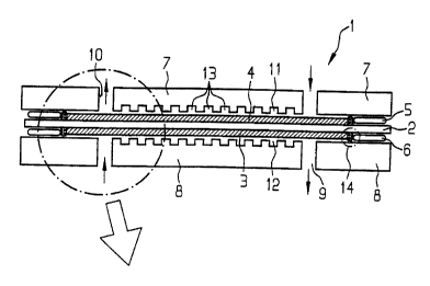
Figure 1 shows a fuel cell 1. The membrane 2, which
extends over the entire length of the cell, is in the
center. The membrane is coated on both sides with the
electrodes 3 and 4, as far as the edge. The seals 5 and
6, which adjoin the two sides of the membrane where the
electrodes stop, can be seen at the edge . The terminal
plates 7 and 8, which delimit the two reaction spaces
CA 02340046 2001-02-09
WO 00/10215 - 4 - PCT/EP99/04570
11 and 12 of the fuel cell 1 on the opposite side from
the membrane 2, can be seen at the top and bottom.
The cross section through the fuel cell 1 selected in
Figure 1 is taken through the supply or removal ducts
9/10 for the process gases. Therefore, in each case two
removal or supply openings, through which the process
gases flow, for example in the direction indicated by
the arrows, can be seen in the terminal plates 7 and 8.
The cell area between the supply and removal ducts is
the active cell area. The edge region of the fuel cell
lies on the other side of the ducts.
In operation, a process gas, for example the fuel,
flows through the distribution ducts 13 into one of the
two reaction spaces 11/12, for example the anode
chamber 11, along the active cell area where the
reaction of oxidant and fuel to form water and current
takes place. The product water is regularly removed
along the active cell area. Hitherto, the active cell
area has been the only point in a fuel cell at which
product water is formed. According to the invention,
reaction now also takes place, to a slight extent, in
the structural edge region of the cell, where the
electrode layers have according to the invention been
extended along the membrane. The process gases reach
this area practically only by diffusion through the
support of the active catalyst layer, i.e. for example
through the carbon paper, since the terminal plates in
the structural edge region do not have any distribution
ducts 13.
As has been stated, the process gas flows in the
structural edge region are small or even nonexistent
and therefore the product water formed there cannot be
removed. Consequently, product water 14 collects in the
gap which forms and adjoins the end of the electrode
layer on the membrane. As a result, a small reservoir
CA 02340046 2001-02-09
WO 00/10215 - 5 - PCT/EP99/04570
of water 14 is formed between the seals S and 6 and the
membrane 2. This reservoir of water offers the
following advantages:
1.) The membrane surface which lies outside the active
electrode surface is always surrounded by water.
Membranes whose mechanical resistance is highly
dependent on the water content can therefore be used
with long-term stability.
2.) Any damage which may be present in the edge region
of the membrane, caused, for example, by hot pressing,
could hitherto, i.e. without the reservoir of water,
have led to gas breakthroughs. On account of the water
cushion which is now present, only gases which are
dissolved in water can diffuse to the membrane. This
quantity of gas is so small that there is no
possibility of local overheating and further damage to
the membrane, such as for example a gas breakthrough.
3.) The membrane is prevented from becoming brittle
and drying out in the edge region.
The region which is circled in Figure 1 is shown in
detail in Figure 2. The membrane 2, which is surrounded
by the seals 5 and 6 at the edge, is arranged in the
center. Toward the center of the cell area, it is
coated with the electrodes 3 and 4, which comprise the
catalyst layers 3a and 4a and the supports 3b and 4b.
The axial supply duct 10, the terminal plates 7 and 8
with their distribution ducts 13 in the reaction spaces
11 and 12 can also be seen. A reservoir of water 14 is
formed at the end of each of the electrode coatings of
the membrane, since the product water which is formed
there cannot be removed.
The novel extension of the electrode layer into the
structural edge region of the fuel cell means that a
CA 02340046 2001-02-09
WO 00/10215 - 6 - PCT/EP99/04570
reservoir of water, which wets the membrane, is formed
in that region in a gap at a location on the membrane.