Note: Descriptions are shown in the official language in which they were submitted.
CA 02340155 2001-02-09
WO 00/09038 ~- PCT/GB99/02628 -
- 1 -
ANCHORING MEANS FOR A JOINT PROSTHESIS OR OTUFF7
COMPONENT
This invention relates to anchoring joint a
prostheses or other component in a bone and, more
particularly, to anchoring means for anchoring a joint
prosthesis or other component, and a method of fitting
the anchoring means, in a bone.
It is a well known medical technique to replace
worn out, damaged or diseased joints in human and animal
bodies with artificial joint prostheses. Such
prostheses may, for example, comprise a replacement
joint articulation, such as a metal ball and socket or
other pivotal means. Alternatively, the joint prosthesis
may replace only part of the joint. For example, the
ball of a ball and socket joint may be replaced with a
joint prosthesis comprising an artificial replacement
ball designed to sit in the original socket of a natural
joint.
Thus, it is intended for the purposes of this
application that the term 'prosthesis' or 'joint
prosthesis' is not limited to a component which takes
the form of a natural joint, but is intended to include
any component for replacing part or all of the function
of a natural joint.
Regardless of whether the joint prosthesis replaces
all or part of a joint, the joint prosthesis, or parts
of the joint prosthesis, needs to be anchored in or
located on bone adjacent or near to the joint. Joint
prostheses therefore generally further comprise means
for anchoring the replacement articulation, joint
surface or joint part in a bone. For example, a joint
prosthesis for replacing a natural ball and socket
joint, such as the human shoulder or hip, often has a
replacement articulation comprising a replacement ball
and socket. The replacement ball may be carried on or
CA 02340155 2001-02-09
WO 00/09038 ~ PCT/GB99/02628 -
- 2 -
formed integrally with anchoring means comprising a pin
arranged to be inserted in the medullary canal of a
bone, such as the femur or humerus, after the natural
ball has been removed. The replacement socket may be
carried in or formed integrally with anchoring means
comprising a cup which is arranged or shaped to be
cemented into the bone surrounding the socket, such as
the acetabulum (hip bone) or scapula (shoulder blade).
Alternatively, the replacement socket may be carried on
or formed integrally with anchoring means comprising a
pin which is inserted into an artificial bore in the
acetabulum (hip bone) or scapula (shoulder bone).
Procedures for fitting joint prosthesis are
generally very invasive. Joints are buried deep in the
human or animal body, so to replace natural joints with
joint prostheses and to insert anchoring means into bone
around a joint requires a large amount of tissue,
including muscle, ligaments and cartilage which support
the joint to be cut. This leads to a long recovery time
for joint replacement operations and a large failure
rate. More recently, however, less or "minimally"
invasive surgical techniques have been developed for
joint replacements. Such a technique is disclosed in
the Applicant's International Patent Application No.
W098/34567, where it is disclosed to carry out a joint
replacement by inserting the replacement parts through a
bore in a bone. Such a bore is made through an incision
distal from the joint being replaced and this reduces
trauma to the tissue surrounding the joint.
According to a first aspect of the present
invention there is therefore provided, a hip prosthesis
comprising a first fastening assembly intended for being
mounted in the hip bone and an anchoring means intended
for being mounted in the top end of the femur, wherein
the first fastening assembly and the anchoring means are
interconnected by means of a pivotable connection,
wherein all parts of the hip prosthesis are so small
CA 02340155 2001-02-09
WO 00/09038 ~~ PCT/GB99/02628 -
- 3 -
and/or slender that they can each be arranged in the
intended end position thereof via a bore in the femur,
which bore extends from the lateral outer side of the
femur through the femoral neck substantially in the
direction of the imaginary longitudinal centre line of
the femoral neck to the femoral head, wherein the
anchoring means of the hip prosthesis in mounted
condition comprises a tapering part, with a relatively
wide, medial side of the tapering part being located
adjacent the femoral neck, while a relatively narrow,
lateral side of the tapering part is located adjacent
the outer side of the femur.
The anchoring means, and indeed the whole hip
prosthesis, may therefore be fitted using a minimally
invasive technique, in which all access to the joint is
gained through the bore in the bone. This vastly
reduces trauma to the area of the joint, and therefore
shortens recovery time and reduces failure rate.
A joint prosthesis similar to this can equally
advantageously be used to replace other human and animal
joints, in particular the human shoulder joint.
However, the type of articulation can vary, as can the
position of the bore. Similarly, the joint prosthesis
may replace only a part of a natural joint, such as only
the ball of a ball and socket joint.
Thus, according to a second aspect of the present
invention there is provided a joint prosthesis having
components which are sufficiently small and slender that
the joint prosthesis is mountable through an extra-
medullary bore in a bone from a position distal to the
intended position of the prosthesis, the joint
prosthesis having an anchoring means which is mountable
in the bore and tapers such that its narrow end is
remote from the joint when mounted.
Also, according to a third aspect of the present
invention there is provided a method of fitting a joint
prosthesis comprising inserting the joint prosthesis
CA 02340155 2001-02-09
WO 00/09038 -- PCT/GB99/02628 -
- 4 -
through an extra-medullary bore in a bone from a
position distal to the intended position of the
prosthesis, and mounting a tapered anchoring means for
or of the joint prosthesis in the bore such that its
narrow end is remote. from the joint when mounted.
The term 'extra-medullary bore' generally refers to
any bore not along the same axis as the medullary canal
of a bone and, in particular, includes any bore across
or through a bone.
These aspects of the invention are advantageous in
that, in a minimally invasive procedure, the tapered
anchoring means provides stable support in the direction
of its main axis toward the joint. In other words, as
force is exerted on the anchoring means by the joint
under natural loading, such as by standing or walking on
a hip, the axial force exerted on the anchoring means is
supported by the taper and the anchoring means will fit
more and more tightly into the bore. Thus, the joint
prosthesis is held very stably in the bone.
However, it will be recognised that this approach
is, to an extent, counter-intuitive since the tapered
anchoring means is inserted into the bore in a bone,
from a position remote from the joint, wide end first.
In particular, when the anchoring means is tapered
before insertion into the bore (e. g. has a permanent
taper), the widest part of the anchoring means (proximal
to the joint) must be inserted first, as the anchoring
means is inserted into the bore from a position distal
from the joint and tapers away from the joint. Thus,
the bore distal from the joint must be at least as wide
as the widest part of the anchoring means and, when the
anchoring means is in position, the diameter of the bore
in the region of the narrower end of the anchoring means
(distal to the joint) is larger than the diameter of the
anchoring means and the anchoring means does not fit
tightly into the bore.
In a first group of embodiments of the invention,
CA 02340155 2001-02-09
WO 00/09038 ~~ PCT/GB99/02628 -
- 5 -
which can avoid the use of cement, it is therefore
preferable for the anchoring means to be radially
expandable in the bore.
This enables the anchoring means to be inserted
into the bore and then wedged into position. For
example, the whole anchoring means may be radially
expanded. Alternatively, the anchoring means may be
inserted in the bore in component parts, some of which
may be tapered. The component parts may be then moved
in the bore longitudinally with respect to one another
such that the diameter of the anchoring at a given point
along its length increases. Regardless, the effect of
the radial expansion is to wedge the anchoring means in
position.
The bore may be uniformly cylindrical or itself
tapered. A straight, uniformly cylindrical, bore is
easier to make in the bone and may allow components of
the joint prosthesis to be inserted through the bore
into their intended position easily. A tapered bore
fits a tapered anchoring means more stabily, but may
have smaller dimensions at the end of the bore remote
from the joint than a uniformly cylindrical bore with
the result that the components of the joint prosthesis
may need to be smaller and/or more slender.
This type of expandable anchoring means may be used
in conventional invasive surgical techniques and not
just minimally invasive procedures. Furthermore, the
anchoring means may be used to fix other components for
fitting in bones in human or animal bodies, not just
joint prostheses, in place. For example, an expandable
anchoring means may be used to secure a component
comprising a plate that is fitted to the outside of a
broken or fractured bone for support.
Thus, according to a fourth aspect of the present
invention, there is provided a component for fitting to
or in a bone, the component having an anchoring means
insertable into a bone cavity and radially expandable in
CA 02340155 2001-02-09
WO 00/09038 -- PCT/GB99/02628 -
- 6 -
the bone such that the anchoring means has a tapered
configuration, with the narrow end of the taper furthest
from the component.
The bone cavity may, in this aspect, be a naturally
occurring bone canal, or may be a bore formed by a
surgeon especially for the prosthesis.
Also, according to a fifth aspect of the present
invention, there is provided a method of anchoring a
component to or in a bone, the method comprising
inserting an anchoring means into a cavity in the bone,
radially expanding the anchoring means in the cavity
such that the anchoring means has a tapered
configuration with the narrow end of the taper furthest
from the component.
In particular, the anchoring means may be radially
expandable such that its outermost diameter exceeds the
diameter of an inlet opening of the cavity. Thus, once
the anchoring means has been expanded it is unable to
pass through the inlet opening and this provides
particularly secure fixation.
In a preferred embodiment of the above aspects, the
anchoring means comprises a pin and one or more
retaining elements, at least one of the pin and/or
retaining element being tapered. The pin and retaining
element{s) can be inserted in the bore separately or
together, but can be moved relative to one another,
substantially in the direction of their major axes, such
that the diameter of the anchoring means is be increased
and a tapered, wedging effect is obtained.
Preferably the anchoring means has two retaining
elements sandwiching the pin. This provides more stable
location in the bore as the pin may extend substantially
along the major axis of the bore and an even load may be
exerted on the retaining elements.
If the anchoring means is expanded to suitable
dimensions it may be fitted into the bore without the
need for cement, which is used to fix most conventional
CA 02340155 2001-02-09
WO 00/09038 w PCT/GB99/02628 -
joint prosthesis in place. However, the anchoring means
may additionally or alternatively be cemented into
position.
Cement provides secure fixing of the anchoring
means into the bone as it takes the exact form of the
bore, and may seep into the bone surrounding the bore,
before setting. However, one difficulty in cementing an
anchoring means in a bore through a bone from only one
end, as required in the minimally invasive technique
described above, is that it is difficult to prevent
cement from leaking from the other and of the bore as it
is injected, particularly as it preferable to pressurise
the cement to drive air and fluid out of the bore in
order to obtain proper fixation.
Where the invention is adapted for use with cement,
it is preferred that the anchoring means is provided
with a seal for sealing the anchoring means in the
bore, at an end of the bore distal to an end through
which cement is injected. Thus, one end of the bore is
sealed and cement can be injected under pressure from
the other end of the bore without leaking from the
sealed end, for example into a joint cavity.
However, this type of anchoring means could be
inserted into a bore in a bone from either end. It may
therefore be used in conventional invasive surgical
procedures. Furthermore, whilst a tapered anchoring
means is preferred, this may not be essential if the
anchoring means is cemented in position, since the seal
enables cement to be injected under pressure from one
end of the bore and adequate fixation may be obtained
with other shapes of anchoring means.
Thus, according to a sixth aspect of the present
invention, there is provided an anchoring means for a
component for fitting to or in a bone, the anchoring
means insertable in a bore and having a seal for sealing
the anchoring means in the bore at an end of the bore
distal to the end through which cement is injected for
CA 02340155 2001-02-09
WO 00/09038 w PCT/GB99/02628
_ g _
cementing the anchoring means in place.
Also, according to a seventh aspect of the present
invention, there is provided a method of cementing an
anchoring means in a bore through a bone comprising
inserting the anchoring means in the bore, sealing the
anchoring means in the bore at one end, and injecting
cement into the other end of the bore.
Thus, the bore is sealed in order that cement can
be injected around the anchoring means in the bore
without leaking past the seal, for example, into a
joint cavity and interfering with a joint. The seal may
also facilitate placement of the anchoring means along
the central axis of the bore and hold it there while the
cement sets. Thus, a tapering anchoring means can be
inserted from a position distal to the joint, yet still
be anchored securely in the bone.
If cement is used, it is preferable that the
anchoring means comprises a single part. This provides
increased strength and durability over an anchoring
means comprising several sections.
Preferably, the seal is an annular ring around the
end of the anchoring means distal from where cement is
introduced. Alternatively, the seal may be an annular
cap having an annular recess for engaging a resected end
surface of the cortical bone wall of the bone. Another
alternative is for the seal to comprise an inflatable
"O"-ring.- The anchoring means may then further comprise
an internal passage for inflating the "O"-ring with air
or any other suitable medium.
In a preferred embodiment, an additional seal may
be provided at the end of the bore where cement is
provided, such that there is a cavity between the seals
surrounding the anchoring means into which cement may be
introduced under pressure, for example via an orifice in
the second seal. The second seal may also be an annular
ring extending around the anchoring means in order to
assist in its axial location.
CA 02340155 2001-02-09
WO 00/09038 .~ PCT/GB99/02628 - -
g _
In the context of more standard surgical techniques
in which anchoring means for prosthesis are inserted
into a bone cavity or bore from the side facing the
joint, the provision of the cement seal at the opening
where the cement is introduced may be more significant,
since the other end of the cavity or bone may terminate
within the bone and therefore~be effectively sealed
already.
Hence, a further aspect of the invention provides a
prosthesis having an anchoring means configured for
mounting in an extra-medullary bore in a bone, one end
of the anchoring means being provided with an annular
seal through which cement may be forced into the bone in
use.
A further aspect of the invention provides a method
of anchoring a prosthesis in an extra-medullary bore in
a bone, comprising locating a tapered anchoring
component in the bore, sealing the bore opening and
forcing cement under pressure into the bore with the
anchoring means positioned therein.
In the context of a hip replacement, the bore
preferably extends along approximately the imaginary
longitudinal centre line of the femoral neck and the
prosthesis in an artificial ball joint.
These latter aspects can provide a less invasive
technique and a firmer mounting than standard hip
replacement procedures.
One of the fundamental advantages of the invention
is the stable support provided for a joint prosthesis by
a tapering anchoring means. This is particularly
advantageous for hip prosthesis which may bear a large
load and therefore require particularly stable support.
According to a further aspect of the present
invention there is therefore provided a hip prosthesis
having an anchoring means for supporting the prosthesis
in an extra medullary bore in a femur, the anchoring
means being tapered away from the prosthesis and
CA 02340155 2001-02-09
WO 00/09038 ~~ PCT/GB99/02628 -
- 10 -
extending only part way through the femur.
Thus, a relatively small and simple anchoring means
may be used to support the hip prosthesis, yet this
still provides stable and strong support for the
prosthesis. Such an anchoring means is relatively cheap
to produce and causes far less trauma to the femur than
conventional femoral components for hip protheses which
sit in the medullary canal of the femur or extend all
the way across the bone.
Preferred embodiments of the present invention will
now be described, by way of example only, with reference
to the accompanying drawings, in which:
Fig. 1 is a sectional view of the top of a femur in
which an anchoring means according to a first exemplary
embodiment of the invention has been fitted;
Fig. 2 is a cross-sectional view of the anchoring
means of Fig. 1, taken on the line II-II of Fig. 1;
Fig. 3 is a sectional view similar to that of
Fig. 1, showing an anchoring means according to a second
exemplary embodiment of the invention;
Fig. 4 is a cross-sectional view of the anchoring
means of Fig. 3, taken on the line IV-IV of Fig. 3;
Fig. 5 shows a detail of the cross-sectional view
of Fig . 4 ;
Fig. 6 is a sectional view similar to Fig. 1,
showing an anchoring means according to a third
exemplary embodiment of the present invention;
Fig. 7 is a sectional view similar to Fig. 1,
showing an anchoring means according to a fourth
exemplary embodiment of the present invention;
Figs. 8a-8e show some steps for mounting the
anchoring means shown in Fig. 1 in a femur;
Fig. 9 is a sectional view similar to Fig. 1,
showing an anchoring means according to a fifth
exemplary embodiment of the present invention;
Fig. 10 is a close-up sectional view similar to
Fig. 1, showing an anchoring means according to a sixth
CA 02340155 2001-02-09
WO 00/09038 ~- PCT/GB99/02628 - -
- 11 -
exemplary embodiment of the present invention; and
Fig. 11 is a close-up sectional view similar to
Fig. 1, showing an anchoring means according to a
seventh exemplary embodiment of the present invention.
Joint prostheses may be used to replace virtually
all joints in the human and animal body. Likewise, this
invention may be used in the replacement of any joint in
the human and animal body. However, it is particularly
applicable to the replacement of hip and shoulder joints
and, for convenience, preferred embodiments will be
described with reference to the replacement of the human
hip joint, and relate, in particular, to a hip
prosthesis in accordance with than described in
International Patent Application No. W098/34567.
In the Figures, only an anchoring means of
different embodiments of a hip prostheses is shown. An
example of a possible embodiment of a complete hip
prosthesis may be found in International Patent
Application W098/34567, the subject matter of which is
to be regarded as being inserted herein. The Figures
show different exemplary embodiments for fitting an
anchoring means (the second fastening assembly of
W098/34567) in a femur F. As is described in detail in
W098/34567, the parts of the hip prosthesis are
preferably designed such that they can all be placed
into their end positions through a bore in the femur,
which bore extends from the lateral outer side Fo of the
femur F through the femoral neck F~. The bore may be
substantially in the direction of the imaginary
longitudinal centre line of the femoral neck to the
femoral head. During the positioning of the hip
prosthesis, a relatively small incision is made in the
leg, providing access to the lateral outer side of the
femur F. Next, a bore is made in the femur F as
described hereinabove. Via this bore, the femoral head
is removed with a special tool, described in the above-
cited International Patent Application. Next, parts of
CA 02340155 2001-02-09
WO 00/09038 ~ PCT/GB99/02628 -
- 12 -
the joint prosthesis can be mounted in the hip bone via
the bore in the femur F. After the positioning of the
first fastening assembly, the anchoring means of the
invention can be mounted. In the present exemplary
embodiments, the anchoring means, in mounted condition,
comprises a tapering part C. A wide, medial side CM of
the tapering part C is located more adjacent the femoral
neck F~, while a narrower, lateral side CL of the
tapering part C is located more adjacent the outer side
Fo of the femur F. Because the tapered part C tapers from
the medial to the lateral side or away from the joint
articulation, the hip prosthesis, when the leg is
subjected to a normal load, is pressed into the bore in
the femur F more and more tightly. Hence, the specific
geometry provides the anchoring means with a self-
locking action.
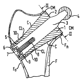
In all exemplary embodiments shown in Figs. 1-7,
the anchoring means comprises a pin 3, respectively 13,
33, 43. The pin 3, 13, 33, 43 has a free, medial end
thereof provided with means for forming at least a
portion of the pivotable connection. In the present
exemplary embodiments, this portion is designed as a
ball 4, 14, 34, 44 of a ball joint. It is readily
understood that other pivotable connections are also
possible. For this, reference is made to W098/34567.
The anchoring means of the present exemplary embodiments
also comprises two retaining elements, respectively 1,
2; 11, 12; 31, 32; 41, 42. The retaining elements 1, 2;
11, 12; 31, 32; 41, 42 in mounted condition bound a hole
into which the pin 3, 13, 33, 43 is at least partially
inserted. In the present exemplary embodiments, the two
retaining elements 1, 2; 11, 12; 31, 32; 41, 42 taper
from a medial end CM proximal to the pivotable
connection, to a lateral end CL. The retaining elements
1, 2; 11, 12; 31, 32; 41, 42 are dimensioned such that
they can be moved through the bore in the femur F as
long as the pin 3, 13, 33, 43 is not yet fitted or
CA 02340155 2001-02-09
WO 00/09038 . PCT/GB99/02628 -
- 13 -
inserted far enough into the hip joint cavity or bore.
The exemplary embodiments of Figs. 1-6 comprise a
pin 3, 13, 33 having a constant sectional profile at
least over a part of its length. The hole bounded by
the two retaining elements 1, 2; 11, 12; 31, 32 likewise
has a substantially constant sectional profile, into
which the part of the pin 3, ~13, 33 with the constant
sectional profile is at least partially inserted. Such
construction has the advantage that the retaining
elements 1, 2; 11, 12; 31, 32 can be moved into their
end positions, whereupon the pin 3, 13, 33 can be
positioned.
Because in such embodiments, the pin 3, 13, 33 can
still move relative to the retaining elements 1, 2; 11,
12; 31, 32, means for connecting the retaining elements
1, 2; 11, 12; 31, 32 and the pin 3, 13, 33 is provided.
In Fig. 1, these means are formed by screw thread 5
provided on the pin 3. The retaining elements 1, 2 have
their lateral ends provided with internal screw thread
mating with the screw thread 5 on the pin 3. To prevent
the pin 3 from moving after it is rotated into a
specific position, a locking means is provided which in
the present exemplary embodiment comprise a sleeve 6
having and end wall. The sleeve 6 embraces or surrounds
the lateral ends of the retaining elements 1, 2. Means
for connecting the sleeve 6 to the pin 3 is also
provided and, in the present exemplary embodiment, the
means for connecting the sleeve 6 to the pin 3 comprise
a bolt 7. Provided in the end wall of the sleeve 6 is
an end wall bore 9. In line with this end wall bore 9,
a pin bore 8 is provided in the pin 3, substantially
along the major axis of the pin 3. The bolt 7 passes
through the end wall bore 9 and engages the pin bore 8.
As the bolt 7 is tightened, the sleeve 6 is drawn
further over the lateral ends of the retaining elements
1, 2. Because these lateral ends 10 are of a slightly
tapered design and, moreover, the inner circumferential
CA 02340155 2001-02-09
WO 00/09038 -- PCT/GB99/02628 -
- 14 -
wall of the sleeve 6 is also of tapered design, the
retaining elements 1, 2 are pressed together when the
bolt 7 is tightened, causing the pin to be clamped
between the retaining elements 1, 2. Moreover, the
pulling force exerted by the bolt 7 prevents rotation of
the pin 3 relative to the retaining elements 1, 2, by
the friction occurring in the screw thread connection 5.
In the exemplary embodiment shown in Fig. 3, the
pin 13 has a constant sectional profile, viewed in the
longitudinal direction of the pin 13. As Fig. 4 clearly
shows, in the transverse direction, the pin 13 is
provided with tapered faces 15 which axe receivable in
the hole bounded by the retaining elements 11, 12. In
the present exemplary embodiment, the tapered faces 15
and the hole formed by the retaining elements 11, 12 are
provided with serrated or snap edges preventing an axial
displacement of the pin 13 relative to the retaining
elements 11, 12. To ensure that the tapered faces 15 of
the pin 13 are properly pressed into the associated
opening in the retaining elements 11, 12, this exemplary
embodiment, too, has locking means comprising a sleeve
16 having an end wall with an opening 19 provided
therein. The sleeve 16 is tightened by means of a bolt
17 engaging a pin bore 18. Because this sleeve 16, too,
comprises tapering circumferential walls 20, the
retaining elements 11, 12 will be pressed together
during tightening of the bolt 17. When the retaining
elements 11, 12 are being moved together, the tapered
faces 15 of the pin 13 engage the associated tapered
faces in the retaining elements 11, 12 more and more
tightly. The serrated snap edges of the tapered faces
15 which are clearly shown in the detail of Fig. 4 shown
in Fig. 5 provide a firm connection between the pin 13
and the retaining elements 11, 12. The tapered outer
surface C of the retaining elements 11, 12 provides that
when the hip prosthesis is subjected to a normal load,
the fastening assembly is pressed into the femur F more
CA 02340155 2001-02-09
WO 00/09038 ~~ PCT/GB99/02628 -
- 15 -
and more tightly.
In the exemplary embodiment shown in Fig. 6, the
means for connecting the retaining elements 31, 32 and
the pin 33 are exclusively formed by a screw thread 35
provided on the pin 33 and mating with internal screw
thread provided on the inside of the retaining elements
31, 32.
Unlike the previous exemplary embodiments, the
exemplary embodiment shown in Fig. 7 has a pin 43
tapering over at least a part of the length thereof.
The tapered pin part tapers to the lateral end 43L,
viewed from the medial end 43M. Viewed from the medial
to the lateral end of the hole, the hole bounded by the
two retaining elements 41, 42 has a tapering sectional
profile in which the tapering pin part 43 is at least
partly received. Here, the connection between the
retaining elements 41, 42 and the pin 43 is effected by
drawing the pin 43 continuously to the lateral side.
This is effected in that the means for connecting the
retaining elements 41, 42 to the pin 43 comprise a
drawing plate 46 and a wire of memory metal 45. The
wire of memory metal 45 is by a first end thereof
connected to a medial end 43M of the pin 43. The second
end of the wire 45 is connected to a drawing plate 46.
In mounted condition, the drawing plate 46 abuts against
the outer side Fo of the femur F at the location of the
lateral end of the femoral bore. The wire of memory
metal 45 is designed such that at body temperature it
tends to shorten, causing a tensile stress in the wire.
During positioning of the wire 45, it is in a stretched
condition, so that during positioning some play is
present for fitting the pin 43 and the retaining
elements 41, 42. Although in the Figure the retaining
elements 41, 42 have a slightly tapered configuration,
this is not required, because the tapered configuration
of the anchoring means may be entirely provided by the
pin 43.
CA 02340155 2001-02-09
WO 00/09038 w PC'T/GB99/02628 -
- 16 -
In the exemplary embodiment shown in Fig. 7, the
retaining elements 41, 42 are moreover further provided,
at their medial ends, with a collar 47, 48 intended for
engagement with the.cortical bone edges bounding the
medial opening of the femoral bore. If necessary, such
collar could also be provided in the other exemplary
embodiments.
Figs. 8a-Se show the successive steps for mounting
the anchoring means shown in Fig. 1. First, the
retaining element 1 is positioned (Fig. 8a); then, the
retaining element 2 is positioned (Fig. 8b); after that,
the pin 3 is provided in the hole bounded by the
retaining elements 1, 2 (Fig. 8c); then, the sleeve 6 is
slid over the lateral ends of the retaining elements 1,
2 (Fig. 8d). Finally, the bolt 7 is tightened, after
which the anchoring means has been mounted in the femur
F (Fig. 8e) .
It is observed that before the pin is positioned,
the retaining elements may temporarily be slid slightly
deeper into the joint, as a result of which the hole
bounded by the retaining elements 1, 2 is slightly wider
for inserting the pin 3 therein. The retaining elements
1, 2 may subsequently be pulled back in lateral
direction into their end positions, after which the
connection between the pin 3 and the retaining elements
1, 2 is effected.
The above embodiments all have two retaining
elements 1, 2; 11, 12; 31, 32; 41, 42. However, all of
these embodiments may be modified by providing only a
single retaining element 1, 2; 11, 12; 31, 32; 41, 42.
For example, referring to Fig. 1, the retaining means 2
may be formed integrally with the pin 3, such that the
anchoring means substantially comprise only two elongate
components; the pin 3 and retaining means 1.
Alternatively, the retaining means 2 can be omitted and
the bore made to different dimensions such that the
upper surface of the pin 3 (as shown in Fig. 1) contacts
CA 02340155 2001-02-09
WO 00/09038 - PCT/GB99/02628 -
- 17 -
the bone directly.
Referring to Fig. 9, in a fifth embodiment of the
present invention a pin 53 has a substantially conical
shape, tapering from a medial end, proximal to a joint
articulation 54 to a lateral end, distal to the joint
articulation 54. The pin 53 may be arranged to fit
directly into a prepared bore in a femur from the
location of the prosthesis, i.e. using a conventional
(invasive) surgical technique. In that case, the pin 53
is shorter than shown in Figure 9 in order that it
extends only part way through the femur F and the
cortical bone wall opposite the joint articulation 54
remains intact, i.e. the bore does not extend all the
way through the femur F.
However, the example shown in Figure 9 is suitable
for use in a minimally invasive surgical technique such
as that described in W098/34567 and has a medial seal 51
is provided at its proximal end around the circumference
of the pin 53. The medial seal 51 is generally annular.
A lateral seal 52 is provided at the lateral end of the
pin 53 distal from the joint articulation 54, which is
again annular and disposed around the circumference of
the pin 53.
The pin 53 is fitted in a bore 55, in this example
in a femur F. The medial seal 51 seals the medial end
of the bore and helps to locate the pin 51 centrally in
the bore. The lateral seal 52 is then fitted at the
distal end of the pin, and seals the lateral end of the
bore. There is a cement delivery orifice 58 in the
lateral seal 52 through which cement is injected into an
elongate annular space 57 between the pin 53 and the
bore. The cement is delivered at a pressure generally
higher than normal blood pressure in order that any
fluid is driven out of the space 57 and the cement abuts
the bone over the whole exposed inside surface of the
bore. Preferably, the cement also permeates the
Spongiform bone of the inside of the femur surrounding
CA 02340155 2001-02-09
WO 00/09038 ~ PCT/GB99/02628 -
- 18 -
the bore to some degree dependent on the type of cement
used and the pressure it is delivered at. This provides
a more secure interface between the cement and bone F
when the cement has set.
When the cement sets, the pin 53 is held rigidly in
the bore. Any force exerted from the joint articulation
end of the pin 53, for example through weight put on the
hip prosthesis in use, forces the pin 53 towards its
lateral or distal end, and due to the taper of the pin
53 forces the cement radially outwards. Thus, if the
pin 53 moves at all, it pushes more and more tightly
into the femur.
In Fig. 9, the bore is shown as uniformly
cylindrical. The bore may, however, be generally
conical, tapering in the same direction as the pin 53.
Referring to Fig. 10, a sixth embodiment of the
present invention is largely similar to the fifth
embodiment shown in Fig. 10. However, in this example,
a cap 60 is provided to seal the end of the bore
proximal to the joint articulation 64.
The cap 60 has an annular recess 61 which holds a
gasket or seal 62. The seal engages a rim of cortical
bone around a resected femoral neck to seal the bore and
hold the cap 60 in place. An annular resilient means 65
is provided inward of the recess 61 which presses
against the inside surface of the cortical bone wall of
the femoral neck to fit the cap 60 more securely. The
resilient means 65 need not be annular and plural
separate resilient means can be provided around the cap
60 instead.
The pin 63 extends through the cap 60 and is
attached to the cap 60 by an external screw thread 66 on
the pin 63. The cap is put in place first, and the pin
63 is then located and screwed into the cap 60. Due to
the dimensions of the cap 60, if it is required to pass
the cap 60 through the femoral bore to put the cap 60 in
place for example when using the minimally invasive
CA 02340155 2001-02-09
WO 00/09038 -- PCT/GB99/02628 - -
- 19 -
technique described above, the cap 60 is collapsable or
made from deformable material to fit through the bore.
The screw thread 66 may self tap into soft material
disposed on the cap 60 or engage a screw thread on the
cap 60.
Referring to Fig. 11, a seventh embodiment of the
present invention is again largely similar to the fifth
embodiment shown in Fig. 9. However, in this embodiment
the medial seal 55 shown in Fig. 9, is an annular
inflatable seal 70. The inflatable seal is connected to
an air passage 71 inside the pin 73.
Thus, when the pin 73 is fitted, the seal is
inflated such that it locates the pin 73 centrally in
the bore and seals the medial or proximal end of the
bore.
It may be understood that the invention is not
limited to the exemplary embodiments described, but that
various modifications are possible within the scope of
the invention defined in the claims.