Note: Descriptions are shown in the official language in which they were submitted.
CA 02340502 2001-03-12
1
QUICK RELEASE DEVICE FOR A TIRE MOLD PLATE
BACKGROUND AND SUMMARY
The invention relates to molds for manufacturing new tires and molds for
retreading tires. More particularly, the invention relates to a device for
easily releasing a
removable plate from a hot mold.
Such pocket plates are inserts for a mold side wall ring that are used to mold
information onto a tire sidewalk for example, tire brand information or a bar
code for
inventory identification. A mold side wall ring may be used over a relatively
long period
of time. and for molding different versions of a single tire model. The
removable plates
are changed when the information on the plate needs to be changed for
different tire
molding requirements.
In conventional molds, pocket plates are held in place in a mold by magnets.
by
screws fastened from the front of the plate, or by screws fastening the plates
from the
back of the side wall ring. In the case of magnets, when the mold is heated,
the side wall
ring and plate expand, which provides friction to help hold the plate in
place.
The conventional means of holding pocket plates in side wall rings present
drawbacks. In molds in which the plates are fastened with front attaching
screws. the
screw heads leave a mark on the molded tire. When the screws are fastened from
the
back of the plate. the mold must be first removed from the press to gain
access to the
screws. Once the plate is changed. the mold must be reinstalled and realigned
in the
press, wfiich involves time and effort. The magnet fastened plates must be
allowed to
CA 02340502 2001-03-12
2
cool before they can be removed, which causes delay, and additionally are
difficult to
grasp for removal because of the lack of an edge or grip on the surface of the
plate.
The present invention provides a device for quickly and easily removing pocket
plates from a mold. According to the invention, a mold half has a recess to
receive a
pocket plate. A rod inserted in a hole in a mold half part, a first end of the
rod being
disposed at an accessible outer surface of the mold half part, a second end of
the rod
disposed in a position adjacent to the pocket plate recess. The rod is movable
in the hole
and includes a cam surface that is selectably moved into the recess to push on
the pocket
plate by movement of the rod.
According to another aspect of the invention. the rod is rotatable in the hole
and
the cam is radially arranged on the rod for movement upon rotation. In
addition, the
second end include a hook radially opposite the cam surface for engaging a
catch on the
back surface of the pocket plate to secure the pocket plate in the recess.
According to an alternative embodiment of the invention, the rod is slidable
in the
hole. and the cam is linearly arranged on the second end of the rod. The rod
includes a
tab that engages a slot in the pocket plate to selectably secure the pocket
plate in the
recess.
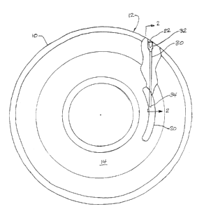
BRIEF DESCRIPTION OF THE DR:4WINGS
Fig. 1 is a top view of a tire mold part showing in partial section a quick
release
device in accordance with the invention;
Fig. 2 is a section view of the mold part taken along the lines 2-? in Fig. 1;
Fig. 3 is a section view of the mold part taken along the lines 3-3 in Fig. 2;
and
CA 02340502 2001-03-12
3
Fig. 4 is a section view according to lines 2-2 of Fig. 1 showing an
alternative
embodiment of the invention.
DETAILED DESCRIPTION
Fig. 1 is a top view of tire mold part 10. As will be understood by those
skilled in
the art, the tire mold part 10 will contact and form one sidewall of a tire. A
second mold
part (not illustrated) forms the opposite sidewalk and tread forming segments
(also not
illustrated) are positioned in the radial direction to the two mold parts. The
assembled
mold parts and tread segments are placed in a press that holds the assembled
parts
together as they are heated to cure the tire. The drawings are not to scale.
and the
dimensions of various features have been exaggerated or reduced to improve the
clarity of
the figures.
The tire mold part 10, and the opposite mold part, include aspects that mold
information and ornamental features into the tire sidewall. For example. the
brand name
and model of the tire. the tire size, load, and pressure specifications may be
molded onto
the sidewall. Some information for a given tire mold may require occasional
change. For
example, when the mold is used to make tires for a private label customer. the
brand
name will change. For such information. the mold part typically includes a
removable
plate (not illustrated in Fia. 1 ) that is inserted in a recess 2U in the mold
part 10.
The invention is directed to a device to allow the quick and easy removal of
such
plates. In conventional molds, such plates are held in the mold by screws.
either
mounting from the front or rear of the plate, or by magnets. Removal of plates
held by
either means is awkward and time consuming.
CA 02340502 2001-03-12
4
According to the invention, a rod 30 is inserted in a hole 22 in the mold part
10.
The hole 22 extends from an outer surface 12 of the mold part 10 to a position
adjacent
the recess 20. A first end 32 of the rod 30 is disposed at the outer surface
12 so that it
may be manipulated to move the rod. as described below. A second end 34 of the
rod 30
is disposed adjacent the recess 20.
The rod 30 is movable in the hole 22 to effect release of a plate in the
recess 20.
Fig. 2 is a section view of the mold part of Fig. 1 taken along the lines 2-2
in Fig.
1. A plate ~0 is inserted the recess 20 in the mold part 1Ø In the
illustrated view, the
recess 20 is formed in a side wall ring 14 of the mold part 10. As may be
seen. the rod 30
extends to a position adjacent the recess 20. In the embodiment illustrated in
Fig. 2, the
rod 30 is rotatable in the hole 22. The first end 32 of the rod 30 includes
tool engaging
means, a hex head hole, a slot. or other suitable structure. The second end 34
includes a
cam 36. shown in Fig. 3. Turning the rod 30 causes the cam surface 36 to
contact and
press against the plate ~0. The cam surface 36 is shaped so that it will push
the plate ~0
sufficiently free of the recess 20 to be removed by an operator.
According to another aspect of the invention illustrated in Fig. 3. the second
end
34 of the rod 30 includes a hook 38 oppositely disposed from the cam surface
36. The
plate ~0 includes a catch ~2 that couples with the hook 38 when the rod 30 is
rotated
appropriately. The hook 38 and catch ~2 serve to secure the plate in the
recess 20.
An alternative embodiment is illustrated in Fig. 4. The rod 31 is slidable in
the
hole in the mold part 10, and includes a linear cam 37 formed on the second
end 3~. By
pulling the rod in the left direction in the figure, the linear cam 37 will
contact and press
on the bottom face ~3 of the plate ~ 1, causing it to raise out of the recess
20. The rod 3 I
CA 02340502 2001-03-12
could, of course, be arranged so that pushing, rather than pulling, causes the
linear cam
37 to engage the plate ~ 1. A spring or other device could be installed in the
hole 22 to
bias the rod 31 to a neutral position.
The slidable rod 31 includes a tab 39 spaced from the linear cam 35 that
engages a
slot >j formed in the plate ~ 1 when the rod is moved to a forward position to
secure the
plate in the recess 20.
A mold part can have as many removable plates and release devices as needed.
The present invention is not limited to a particular mold type, and those
skilled in the art
will understand how to apply the principles of the invention to various molds.
The
described structures and embodiments are meant to be illustrative and not
limiting. and
those skilled in the art will appreciate that substitutions of equivalents may
be made
without departing from the scope of the inventions as defined by the following
claims.