Note: Descriptions are shown in the official language in which they were submitted.
CA 02340561 2001-03-12
1
ABSORBENT ARTICLE
BACKGROUND OF THE INVENTION
1. Field of the Invention
The present invention relates mainly to an absorbent
article for absorbing and retaining a liquid waste such as
menstrual blood and, more particularly, to an absorbent article
having leakage preventing side walls on the two widthwise sides
of the liquid receiving side.
2. Related art
In the prior art, there have been a variety of absorbent
articles including a sanitary napkin, a urine absorbing pad and
a disposable diaper. These absorbent articles are demanded,
when worn, for absorbing the liquid waste reliably in liquid
absorbing layers so that the liquid waste may not leak to the
outside of the absorbent articles. For this purpose, there is
an absorbent article which is provided on the surface of the
liquid receiving side with leakage preventing side walls
extending longitudinally on the two widthwise sides.
In the general structure of the leakage preventing side
walls of the prior art, a longitudinally Extending hydrophobic
sheet is jointed to the top sheet of the albsorbent article, and
an elastic member extending longitudinally of the absorbent
article is jointed to the hydrophobic sheet. By the elastic
shrinking force in the longitudinal direction of the elastic
CA 02340561 2006-03-15
2
member, a curving force in the longitudinal direction is
applied to the absorbent article, and the leakage preventing
side walls are raised to the liquid receiving side of the
absorbent article so that the menstrual blood or the like
may be prevented from leaking sideways.
In Japanese Patent Laid-Open No. 215244/1996, published
August 27, 1996, (now Japanese Patent No. 2909877), for
example, there is disclosed an absorbent article, the
leakage preventing side walls of which are made of a
synthetic resin film formed into a non-planar shape. In
this absorbent article, the leakage preventing side walls
thus subjected to the non-planar treatment to form
longitudinal wrinkles are brought into facial contact with
the skin of a wearer.
However, this absorbent article of the prior art has
been frequently unable to guide the menstrual blood or the
like, as having blotted the surfaces of the leakage
preventing side walls, reliably to the side of the liquid
absorbing layer so that the wearer is made to feel a
physical disorder with the menstrual blood residing on the
leakage preventing side walls and to cause the sideway
leakage. In the structure, as disclosed in Japanese Patent
Laid-Open No. 215244/1996, published August 27, 1996 (now
Japanese Patent No. 2909877), the wrinkled leakage
preventing side walls come into facial contact with the skin
of the wearer, so that the menstrual blood or the like is
liable to stay between the wrinkles although the contacts
between the skin and the leakage preventing side walls are
satisfactory. In addition, the leakage preventing side
walls with the
CA 02340561 2001-03-12
3
menstrual blood residing thereon come into facial contact with
the wearer to intensify the uncomfortable feel at the wearing
time.
SUMMARY OF THE INVENTION
The invention has an object to provide an absorbent
article which is enabled to improve the wearing feel and to
prevent the sideway leakage effectively by making it easy to
guide the blotting liquid to the side of the liquid absorbing
layer thereby to suppress the stay of the menstrual blood or
the like on the leakage preventing side' walls.
According to an aspect of the inventi~~n, there is provided
an absorbent article comprising:
a main body including a support sheet, a liquid absorbing
layer laid on the support sheet, and a liquid-permeable sheet
provided on a liquid receiving side of the main body and covering
the liquid absorbing layer; and
leakage preventing side walls provided on two sides of
the main body lying opposite one another in the widthwise
direction and extending in the longitudinal direction, to have
root ends jointed to the surface of the :liquid receiving side
and to have free ends positioned apart from the surface of the
liquid receiving side,
wherein each the leakage preventing side walls is formed
of at least one side wall sheet to have an inner sheet portion
CA 02340561 2001-03-12
4
facing the widthwise inner side of the absorbent article and
an outer sheet portion facing the widthwise outer side of the
- absorbent article, and
wherein the inner sheet portion are provided with holes
leading to the inside of the inner and outer sheet portions.
In the absorbent article of the invention, the menstrual
blood, urine or the like infiltrates, when it blots the surface
of the side wall sheet forming the leakage preventing side wall,
into the space between the inner and outer sheet portions from
the holes so that it is guided as it is to the root end through
the space between the inner and outer sheet: portions . Therefore,
the liquid having blotted the side wall sheet does not reside
in the side wall sheet but can prevent the sideway leakage
effectively. Moreover, in the case where the leakage
preventing side wall is inclined with its free end directed
toward the widthwise outer side so that the leakage preventing
side wall comes into facial contact with the skin of the wearer,
the liquid hardly stays on the surface of the side wall sheet
to contact with the skin so that the absorbent article is
reluctant to give an uncomfortable feel. to the wearer.
For example, it is preferable that the inner sheet portion
is corrugated and that the holes are formed in at least the ridges
of the corrugations.
With this construction, the liquid can enter the space
between the inner and outer sheet pori~ions of the leakage
CA 02340561 2001-03-12
preventing side wall from the holes. Moreover, when the liquid
enters the space between the confronting inner and outer sheet
portions from the holes, it is retained on the inner faces of
the ridges of the side wall sheet or guided to the root end along
the inner faces of the ridges, so that the liquid is reluctant
to stay on the surface of the side wall sheet facing the skin
of the wearer.
The side wall sheet may be formed of a nonwoven fabric
which is made of hydrophobic f fibers or made hydrophobic ( i. e. ,
subjected to a hydrophobic treatment), or a hydrophobic resin
sheet. The side wall sheet may be given later natural
corrugations by the shrinking force of an elastic member or the
like, without providing corrugations in advance. However, the
preferable side wall sheet is corrugai~ed in the following
manner.
For example, it is preferable that the inner sheet portion
is provided at least in its portion with: the corrugations of
which the ridges and valleys are extended from the root end to
the free end and arranged regularly in the longitudinal
direction; and a flat portion extending in a direction of
crossing the ridges and valleys of the corrugations, and that
the holes are formed in the boundary portion between the ridges
of the corrugations and the flat portion.
With the corrugations being thus foz°med to extend at their
ridges and valleys from the root end to the free end and with
CA 02340561 2001-03-12
6
the holes being formed in the end portions of the ridges, the
menstrual blood or the like infiltrates _Lnto those ridges from
the holes and is guided to the root end along the inner faces
of the ridges.
Here, the term "flat portion" means a smooth surface
portion where the side wall sheet is never corrugated or is
corrugated lower than the aforementioned corrugations.
For example, the holes may be formed by rupturing the side
wall sheet when the corrugations and the f7_at portion are shaped.
If the holes are formed by the rupturing method, they can be
formed at the same step as that of corrugating the side wall
sheet.
The flat portion may extend in the longitudinal direction,
and an elastic member for exhibiting an elastic shrinking force
in the longitudinal direction may be jointed to the flat portion
between the inner and outer sheet portions.
For example, when the inner and outer sheet portions are
formed by folding back the side wall sheet, the flat portion
may be formed at the folded-back portion of the side wall sheet
forming the free end of the leakage preventing side wall. In
an alternative, the flat portion may be formed midway between
the root end and the free end of the leakage preventing side
wall. In another alternative, the flat ;portion may be formed
midway between the root end and the free end of the leakage
preventing side wall, and the leakage preventing side wall may
CA 02340561 2001-03-12
7
be so bent at the flat portion that its portion extending from
the bent portion to the free end may ue directed to the widthwise
outer side.
Moreover, it is preferable that the holes are formed in
or in the vicinity of the root end of the leakage preventing
side wall. With the holes being formed on the side of the root
end of the leakage preventing side wall,, the menstrual blood
or the like, as guided into the space between the inner and outer
sheet portions, is then guided from the holes on the root end
side to the liquid-permeable sheet and :Further to the liquid
absorbing layer.
In order to release the liquid, which has entered the
space between the inner and outer sheet portions, reliably from
the root end side to the liquid-permeable sheet, it is
preferable that the leakage preventing side walls are jointed
at the root ends either onto two side end portions of the
liquid-permeable sheet, as extending outwardly of the liquid
absorbing layer in the widthwise direction, or onto a central
portion of the liquid-permeable sheet, as positioned between
the two side end portions and over the liquid absorbing layer.
If the inner and outer sheet portions are made water-
repellent at their inner faces confronting each other, the
liquid having entered the space between the inner and outer
sheet portions is promptly guided to the root end side.
CA 02340561 2001-03-12
8
BRIEF DESCRIPTION OF THE L)RAWINGS
Fig. 1 is a perspective view showing a sanitary napkin
as an absorbent article according to a first embodiment of the
invention;
Fig. 2 is a perspective view showing a portion of the
sanitary napkin shown in Fig. 1 and including a section taken
along line II - II;
Fig. 3 is a perspective view showing a modification of
the sanitary napkin shown in Fig. 2 and including a section;
Fig. 4 is a perspective view showing a modification of
the sanitary napkin shown in Fig. 3 and including a section;
Fig. 5 is an enlarged perspeP~tive view showing a structure
of a leakage preventing side wall shown in Fig. 2;
Fig. 6 is a perspective view of shaping rolls for forming
a side wall sheet;
Figs. 7A and 7B are developed perspective views of the
shaping faces of the shaping rolls shown in Fig. 6;
Figs. 8A and 8B are enlarged sections taken along lines
A - A and B - B of Fig. 7B; and
Fig. 9 is an enlarged perspective view of a portion of
the side wall sheet which is provided with corrugations, flat
portion and holes.
DESCRIPTION OF THE PREFERRED :EMBODIMENTS
The invention will be described with reference to the
CA 02340561 2001-03-12
9
accompanying drawings. Fig. 1 is a perspective view showing
a sanitary napkin as an absorbent article according to a first
embodiment of the invention and taken from a liquid receiving
side; Fig. 2 is a perspective view showing a portion and
including a section taken along line II - II of Fig. 1; and Fig.
is an enlarged view of a portion showing a free end of a leakage
preventing side wall shown in Fig. 2.
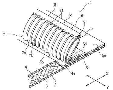
A sanitary napkin 1, as shown in Figs. 1 and 2, is
constructed to have a main body including: a support sheet 2
for confronting an external wear such as <~n underwear; a liquid
absorbing layer 3 positioned on the side of the wearer for
absorbing the liquid waste; and a liquid--permeable sheet 4 for
covering the surface of the liquid receiving side of the liquid
absorbing layer 3 . Side end portions 4a of the liquid-permeable
sheet 4 lying opposite one another in the widthwise direction
(or a direction X) are jointed onto the surface of the support
sheet 2 on two sides of the liquid absorbing layer 3.
On the two side portions of the sanitary napkin 1 lying
opposite one another in the widthwise direction (or the
direction X) , there are provided a pair of leakage preventing
side walls 5 and 5 which extend in the longitudinal direction
( or a direction Y ) . In this embodiment, the individual leakage
preventing side walls 5 and 5 are made of one side wall sheet
6.
The side wall sheet 6 is, for example, made of a
CA 02340561 2001-03-12
hydrophobic nonwoven fabric. This side wall sheet 6 is jointed
at its one end portion 5a onto the support sheet 2 and the side
end portion 4a of the liquid-permeable sheet 4. The side wall
sheet 6 is extended away from the support sheet 2 to form one
root end 5b of the side wall 5 on the side end portion 4a of
the liquid-permeable sheet 4 and is then folded back to form
a free end 5c of the side wall 5. Moreover, the side wall sheet
6 is returned to the support sheet 2 and is so jointed at its
other end portion 5e to the upper face of the support sheet 2
that another root end 5d of the side wall 5 is formed and jointed
onto the side end portion 4a of the liquid-permeable sheet 4.
Therefore, the leakage preventing side wall 5 has a double
structure in which the two folded portions ( or inner and outer
sheet portions 6a and 6b) of the side wall sheet 6 are overlaid
in the widthwise direction (or the direction X).
The side wall sheet 6 is formed with corrugations 7.
These corrugations 7 have ridges 7a and valleys 7b repeated in
the longitudinal direction (or the direction Y). The ridges
7a and the valleys 7b are individually extended in the direction
from the root ends 5b and 5d to the free end 5c of the leakage
preventing side wall 5.
As shown in Figs. 2 and 5, moreover, the side wall sheet
6 is formed with a flat portion (or smooth surface portion) 8.
The side wall sheet 6 is folded back at 'the flat portion 8 to
form the free end 5c. To this free end 5c, moreover, there is
CA 02340561 2001-03-12
11
internally jointed an elastic member 9.. Here, this elastic
member 9 may be arranged at the portion other than the free end
5c, that is, between the root ends 5b and 5d and the free end
5c of the leakage preventing side wall 5.
The side wall sheet 6 having the corrugations 7 exhibits
by itself an elastic shrinking force in the longitudinal
direction ( or the direction Y ) . In addition, the elastic member
9 also exhibits an elastic shrinking force in the longitudinal
direction ( or the direction Y ) . At the two end portions of the
sanitary napkin 1 lying opposite one another in the longitudinal
direction (or the direction Y), the leakage preventing side
walls 5 are jointed to the surface of~ the liquid receiving side
of the main body while falling down outwardly in the widthwise
direction. By the elastic shrinking forces in the direction
Y, therefore, the sanitary napkin 1 is so curved that its liquid
receiving side is recessed in the longii~udinal direction (or
the direction Y), as shown in Fig. 1, and the leakage preventing
side walls 5 are raised at their free ends 5c apart from the
support sheet 2. Here in the embodiment shown in Fig. 2, the
leakage preventing side walls 5 and 5 are so obliquely raised
that the free ends 5c are directed outwardly in the widthwise
direction with respect to the root ends. 5b and 5d.
As shown in Figs. 2 and 5, moreover, in the inner sheet
portion 6a of the side wall sheet 6, there are formed holes (or
openings) 11 which are positioned at 'the boundary portion
CA 02340561 2001-03-12
12
between the corrugations 7 and the flat portion 8 and at the
end portions of the ridges of the corrugat:~ons 7 . The menstrual
blood is infiltrated through -the liquid-permeable sheet 4 and
absorbed by the liquid absorbing layer 3 . When fed to the inner
sheet portion 6a of the side wall sheet 6 constructing the
leakage preventing side wall 5, the menstrual blood is guided
on the surface of the side wall sheet 6 along the valleys 7b
of the corrugations 7 onto the liquid-permeable sheet 4. On
the other hand, the menstrual blood, as might otherwise stay
on the surface of the side wall sheet 6, flows from the holes
11 into the space between the inner and outer sheet portions
6a and 6b of the side wall sheet 6 constructing the leakage
preventing side wall 5 and then migrates along the inner
surfaces of the corrugations 7 to the root end 5b until it is
fed to the liquid-permeable sheet 4.
Here, it is also preferred that the inner sheet portion
6a of the side wall sheet 6 is formed with a flat portion in
or in the vicinity of the root end 5b, and that holes similar
to those on the side of the free end 5c are formed on the side
of the root end 5b . The menstrual blood f lows to the root end
5b between the inner and outer sheet port: ions 6a and 6b and is
fed through the holes opened on the side of the root end 5b to
the liquid-permeable sheet 4, from which the blood is absorbed
through the liquid-permeable sheet 4 by the liquid absorbing
layer 3.
CA 02340561 2001-03-12
13
Here in the embodiment shown in Figs . 1 and 2 , the leakage
preventing side wall 5 is jointed on the- side end portion 4a,
as extended outwardly of the liquid absorving layer 3 in the
widthwise direction, of the liquid-permeable sheet 4. As
described hereinbefore, therefore, the menstrual blood having
migrated through the space between the inner and outer sheet
portions 6a and 6b is fed to the liquid-permeable sheet 4 so
that it is easily led to the liquid absorbing layer 3. In an
alternative, the leakage preventing side walls 5 may be given
the structure in which they rise from th.e central portion, as
located between the two side end portions 4a and 4a and covering
the liquid absorbing layer 3, of the liquid-permeable sheet 4.
With such a structure, also, the menstrual blood having migrated
through the space between the inner and outer sheet portions
6a and 6b can be easily absorbed by the liquid absorbing layer
3.
Fig. 6 is a view for explaining a lheat-pressing step of
forming the corrugations 7 and the flat portion 8 on the side
wall sheet 6 and forming the holes 11 in the boundary portion
between the corrugations 7 and the flat portion 8 at the same
time.
At this heat-pressing step, a nonwoven fabric such as a
melt-blown nonwoven fabric formed of or containing
thermoplastic fibers is heat-pressed by clamping it between
shaping rolls 21 and 22. These shaping rolls 21 and 22 are
CA 02340561 2001-03-12
14
turned in directions a and ~3 while meshing with each other.
The shaping roll 21 has a shaping face formed on its
surface. Fig. 7i~ develops and shows the top plan view ~-of the
shaping face of the surface of the shaping roll 21. In the
shaping face of the shaping roll 21, there are stripe embossed
shaping ribs 23 and grooves 24 which are extended in the axial
direction of the roll and repeated at a constant pitch in the
turning direction ( or the direction a ) . At the axial central
portion of the shaping roll 21, there is formed a bulging
circumference 25 which continues to them upper faces of the
shaping ribs 23 and is extended continuously in the turning
direction (or the direction a).
Fig. 7B develops and shows the shaping face of the surface
of the other shaping roll 22 . In the shaping face of the surface
of the shaping roll 22, there are stripe embossed shaping ribs
26 and grooves 27 which are extended in t:he axial direction of
the roll and repeated at a constant pitch in the turning
direction ( or the direction [3 ) . At the axial central portion
of the shaping roll 22, there is formed a recessed circumference
28 which continues to the bottom portions of the grooves 27 and
is extended continuously in the turning direction (or the
direction (3 ) .
When the shaping rolls 21 and 2.2 come into meshing
engagement, the shaping ribs 23 of the shaping roll 21 and the
shaping ribs 26 of the shaping roll 22 mesh with each other such
CA 02340561 2001-03-12
that the shaping ribs 23 enter the grooves 27 of the shaping
roll 22 whereas the shaping ribs 26 enter the grooves 24 of the
shaping roll 21. At this time, the bulging circumference 25
of the shaping roll 21 bites into the rE~cessed circumference
28 of the shaping roll 22.
When a nonwoven fabric 6A is clamped between the shaping
rolls 21 and 22 and is let off as the rolls turn, as shown in
Fig. 6, the side wall sheet 6 having the corrugations 7, the
flat portion 8 and the holes 11 is formed by the shaping faces
of the shaping rolls 21 and 22.
The side wall sheet 6 is made of a melt-blown nonwoven
fabric, an air-through nonwoven fabric, a, spun-bonded nonwoven
fabric, a point-bonded nonwoven fabric, an air-laid nonwoven
fabric or the like. However, the side wall sheet 6 may be made
of a laminate material of the nonwoven fabric and a resin film,
or a plastic sheet of a low density.
These are made of a thermoplastic resin, and the nonwoven
fabric is exemplified by the PE, PP or PET fibers, or composite
synthetic fibers of the core-sheath type of the PE/PP or PE/PET
or of the side-by-side type thereof.
Fig. 8A is a section showing the shaping face of the
shaping roll 22 and taken along line A - A of Fig. 7B, and Fig.
8B is a section taken along line B - B of Fig. 7B. The shaping
faces of the shaping rolls 21 and 22 are preferably set to a
temperature which is lower by 10°C to 50°C than the melting
point
CA 02340561 2001-03-12
16
of the thermoplastic resin making the aforementioned sheet.
In Fig. 8A, the array pitch of the shaping ribs 26 in the
turning direction ( or the direction (3 ) i;s ihdicated by (31, and
the exceeding size extending through the shaping ribs 26 and
the grooves 27 between the array pitch ~~l is indicated by (32.
When the nonwoven fabric 6A is clamped between the shaping rolls
21 and 22 and let off, the nonwoven fabric; 6A is given a shaping
distortion of f ( ~2 - [31 ) /~1 } . This shaping distortion at this
time is set to a value smaller than the rupture elongation (or
rupture distortion) in the let-off direction of the nonwoven
fabric. As a result, the corrugations 7 are formed without
rupture on the nonwoven fabric 6A.
If the distance, as taken in the roll axis direction, of
the open end of the recessed circumference 28 is indicated by
O1 and if the exceeding size, as adding the undulations in the
widthwise direction, of the recessed circumference 28 is
indicated by 02, as shown in Fig. 8B, the nonwoven fabric 6A
is given a shaping distortion of f ( 02 - O1 ) /O1 } in the roll axis
direction ( or the widthwise direction o:E the nonwoven fabric
6A) . If this shaping distortion is set larger than the rupture
elongation (or the rupture distortion) in the widthwise
direction of the nonwoven fabric 6A, th.e flat portion 8, as
extended in the let-off direction, is formed at the widthwise
central portion of the nonwoven fabric 6A by the shaping rolls
21 and 22, and the holes 11 are formed by the ruptures of the
CA 02340561 2001-03-12
17
nonwoven fabric at the boundary portions between the
corrugations 7 and the flat portion 8, that is, at the end
portions of the ridges of the corrugations 7.
By thus using the shaping rolls 21 and 22 shown in Fig.
6, it is possible to form the corrugations 7, the flat portion
8 and the holes 11 simultaneously. Fig. 9 shows the holes 11
formed by the nonwoven fabric ruptures, :in an enlarged scale.
Here, in order to form the holes 11 by causing the ruptures
in the nonwoven fabric, the rising angle 8' at the two widthwise
side portions of the recessed circumferE~nce 28 is preferably
at least 90 degrees and at most 135 degrees.
In the aforementioned corrugations 7, the fiber density
is higher at the ridges 7a and the valleys 7b and lower at the
side walls 7c. Therefore, the corrugations 7 have cushioning
properties. In the side wall sheets 6 forming the leakage
preventing side walls 5, as shown in Fig. 2, the ridges 7a and
the valleys 7b are extended from the root ends 5b and 5d to the
free end 5c so that the menstrual blood having entered the space
between the inner and outer sheet portions 6a and 6b from the
holes 11 is guided to the root ends along the higher density
portions of the ridges 7a and the valleys 7b.
The density of the higher density portions of the ridges
7a and the valleys 7b is preferably at about 0.1 g/em3. On the
other hand, the opening area of one holes 11 is preferably no
less than 0.0012 cmz. The menstrual blood easily infiltrates
CA 02340561 2001-03-12
18
into the leakage preventing side walls 5 from the holes 11, if
the opening area of the hole 11 is equal to or more than the
above-specified value.
Here, if the confronting inner faces of the inner and
outer sheet portions 6a and 6b forming the leakage preventing
side wall 5, as shown in Fig. 2, are made water-repellent, the
menstrual blood having entered the space between the inner and
outer sheet portions 6a and 6b is promptly guided to the root
end sides. The water-repellent treatment may be made either
by applying a water-repellent hot-melt agent to the inner faces
of the inner and outer sheet portions 6a and 6b or by laminating
the inner sides of the inner and outer sheet portions 6a and
6b with a water-repellent film.
The array pitch (31, as shown in Figs. 8A, i.e., the pitch
of the corrugations 7 is preferable for improving the contact
feel on the skin of the wearer, if it is about 0.5 to 1 mm. On
the other hand, the rising size from the root end 5b to the free
end 5c of the leakage preventing side walls 5 is preferably
within a range of 5 to 25 mm.
The elastic member 9 to be attached to the free end 5c
of the leakage preventing side wall 5 can be made of natural
rubber, synthetic rubber, polyurethane or a styrene-butadiene
copolymer and can take a shape of string, filament, film, band
(or belt) or the like. Alternatively, the elastic member 9 can
be cut from a stretchable nonwoven fabric such as an elastic
CA 02340561 2001-03-12
19
spun-bonded nonwoven fabric or an elastic: melt-blown nonwoven
fabric.
The paired side wall sheets 6 provided with the elastic
member 9 are jointed to the sanitary napkin 1 while being
elongated by about 1.2 to 1.8 times.
The support sheet 2 is preferably made of a liquid-
impermeable sheet. This support sheet 2 may be exemplified by
an air-permeable resin film, a spun-bonded or spun-laced
nonwoven fabric made water-repellent, or a nonwoven fabric
having an air-permeable resin film bonded to the back face.
Here, the support sheet 2 is preferably provided on its back
face with both an adhesive layer to be retained on an external
wear such as an underwear and a release sheet for protecting
the adhesive layer before the sanitary napkin is used.
The liquid-permeable sheet 4 is made of a nonwoven fabric
of PE, PP or PET fibers made hydrophilic or their composite
fibers, such as a spun-bonded nonwoven fabric or a spun-laced
nonwoven fabric. Alternatively, the liquid-permeable sheet 4
is a resin sheet subjected to an opening treatment.
The liquid absorbing layer 3 is made of pulverized pulp
or a mixture of pulverized pulp and a highly water-absorbing
polymer, and is prepared by enveloping the pulverized pulp or
the mixture of the pulverized pulp and the highly water-
absorbing polymer by an absorbent sheet such as tissue paper.
Figs. 3 and 4 show modifications of: the sanitary napkin
CA 02340561 2001-03-12
shown in Fig. 2.
In the modification shown in Fig.. 3, the inner'sheet
portion 6a of the side wall sheet 6 is formed with a flat portion
8a, midway between the root end 5b and t:he free end 5c, which
extends in the longitudinal direction, and the holes 11 are
formed in the boundary portions between tlhe flat portion 8a and
the upper and lower corrugations 7. In this case, the holes
11 are preferably formed in the root end 5b, too, and may also
be formed in the free end 5c as in Fig. 2.
Fig. 4 shows a modification of the sanitary napkin shown
in Fig. 3. In this modification shown in Fig. 4, as in Fig.
3, the flat portion 8a is formed midway between the root end
5b and the free end 5c, and the holes 11 are :formed in the boundary
portions between the flat portion 8a and the upper and lower
corrugations 7. Moreover, an elastic member 9a is jointed to
the inner side of the flat portion 8a. The leakage preventing
side wall 5 is so folded into the shape of letter "L" across
that flat portion 8a that the folded portion from the flat
portion 8a to the free end 5c is directed t.o the widthwise outer
side. In this case, too, the holes 11 may be formed in the root
end 5b and/or the free end 5c.
In Figs . 3 and 4 , the menstrual blood eas ily infiltrates ,
when it blots the surface of the inner sheet portion 6a of the
side wall sheet 6, into the leakage preventing side wall 5 from
the holes 11 opened in the midway portion.
CA 02340561 2001-03-12
21
Here in the embodiments shown in Figs . 2 to 4 , the s ingle
side wall sheet 6 is folded back at the free end 5c so that the
leakage preventing side wall 5 is formed of the two folded
portions (i.e., inner and outer sheet portions) of the single
side wall sheet 6. However, the leakage preventing side wall
may also be formed of two or more side w<~11 sheets by jointing
them one another. For example, a side wall sheet raised from
the root end 5b and another side wall sheet raised from the root
end 5d can be jointed at the free end 5c or at another region
to form a jointed portion extending in the longitudinal
direction (or the direction Y).
In the leakage preventing side wall 5, the outer sheet
portion 6b may be formed with the corrugations 7 like the inner
sheet portion 6a, or may not be corrugated. Here, it is
preferable that the holes 11 are not formed in the outer sheet
portion 6b.
The holes 11 may be formed not by rupturing the nonwoven
fabric but by opening the same by the pin-pressing method.
Although the invention has been described on the
embodiment in which the absorbent article is embodied by the
sanitary napkin, it can also be applied to a disposable diaper,
a urine absorbing pad or another absorbent article.
According to the invention, as h<~s been described in
detail hereinbefore, the liquid having blotted the leakage
preventing side walls is guided thereinto so that it is not left
i ;'
CA 02340561 2001-03-12
22
on the surfaces of the leakage preventing side walls . Therefore,
the sideway leakage can be prevented and the'contact feel of
the skin of the wearer with the leakage preventing side walls
can be improved.
Here, 'comprises/comprising' when used in this
specification is taken to specify the presence of stated
features, integers, steps or components but does not preclude
the presence or addition of one or more other features, integers,
steps, components or groups thereof.
Although various exemplary embodiments have been shown
and described, the invention is not limited to the embodiments
shown. Therefore, the scope of the invE~ntion is intended to
be limited solely by the scope of the claims that follow.