Note: Descriptions are shown in the official language in which they were submitted.
CA 02340575 2001-03-13
PATENT
SEMI-TRACTOR FIFTH WHEEL SENSOR AND
RAIL CAR STANCHION SENSOR FOR A TRAILER
BACKGROUND OF THE INVENTION
This invention is generally directed to a novel
system that senses the presence of a semi-tractor as the
mechanical connection between a trailer and a fifth wheel
of the semi-tractor is made, or that senses the presence
of a rail car as the mechanical connection between the
trailer and a stanchion plate of the rail car is made.
Currently, some prior art systems sense the presence
of a trailer when the trailer is connected to a semi-
tractor, but these systems require that an electrical
connection or a pneumatic connection be made between the
trailer and the semi-tractor. Mechanical switches have
64025-1 1
CA 02340575 2001-03-13
been used to sense the presence of an electrical
connector, known as the 7-way or J560, or the presence of
the pneumatic connectors, commonly known as "gladhands".
Some prior art systems are configured to electrically
sense that a trailer is connected to the semi-tractor by
sensing the presence of voltage on the J560 connector or
in one of the harnesses. Other systems are configured to
pneumatically sense that the trailer is connected to the
semi-tractor by sensing the presence of air pressure on
the braking supply line from the semi-tractor. A
pressure switch or transducer has been used to accomplish
this pneumatic sensing.
In the prior art, completing an electrical or
pneumatic connection between the trailer and the semi-
tractor is a secondary operation and may be forgotten by
the operator. This can result in an error in the system
operation -- the trailer is connected to the semi-
tractor, but the electrical or pneumatic connection is
not made, so the system determines that the trailer is
not connected to the semi-tractor.
The present invention senses the presence of the
semi-tractor or the rail car without any additional
operation. Other features and advantages of the present
invention will become apparent upon a reading of the
attached specification in combination with a study of the
drawings.
sao2s-i 2
CA 02340575 2001-03-13
SUMMARY OF THE INVENTION
The present invention discloses a system for sensing
the presence of a semi-tractor as the mechanical
connection between a trailer and a fifth wheel of the
semi-tractor is made, or for sensing the presence of a
rail car as the mechanical connection between the trailer
and a stanchion plate of the rail car is made. A sensor
is provided in the floor of the trailer proximate to the
kingpin. The sensor senses the presence of the fifth
wheel or the rail car stanchion plate during the
connection process. Control circuitry on the trailer
processes and uses signals from the sensor to perform
various functions.
BRIEF DESCRIPTION OF THE DRAWINGS
The organization and manner of the structure and
operation of the invention, together with further objects
and advantages thereof, may best be understood by
reference to the following description, taken in
connection with the accompanying drawings, wherein like
reference numerals identify like elements in which:
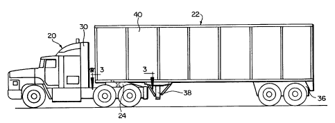
FIGURE 1 is a side elevational view of a trailer
connected to a semi-tractor;
FIGURE 2 is a side elevational view of the trailer
and semi-tractor as shown in FIGURE 1, with the trailer
being disconnected from the semi-tractor;
64025-1
CA 02340575 2001-03-13
FIGURE 3 is a cross-sectional view along line 3-3 of
FIGURE 1;
FIGURE 4 is a cross-sectional view along line 4-4 of
FIGURE 3;
FIGURE 5 is a partial side elevational view of the
trailer connected to a rail car;
FIGURE 6 is a perspective view of a preferred sensor
which is a component in the present invention;
FIGURE 7 is a perspective view of the preferred
sensor which is a component in the present invention; and
FIGURE 8 is an electrical diagram of the preferred
sensor.
~~ozs-i 4
CA 02340575 2001-03-13
DETAILED DESCRIPTION OF THE ILLUSTRATED EMBODIMENT
While the invention may be susceptible to embodiment
in different forms, there is shown in the drawings, and
herein will be described in detail, a specific embodiment
with the understanding that the present disclosure is to
be considered an exemplification of the principles of the
invention, and is not intended to limit the invention to
that as illustrated and described herein.
The present invention provides a novel system that
senses the presence of a semi-tractor 20 as the
mechanical connection between a trailer 22 and a fifth
wheel 24 of the semi-tractor 20 is made, or the presence
of a rail car 26 as the mechanical connection between the
trailer 22 and a stanchion plate 28 of the rail car 26 is
made.
The system of the present invention can be used to
track the location of the trailer 22 when used with a
trailer tracking system, so that the owner of the trailer
22 is able to locate the trailer 22 and to determine
whether the trailer 22 is being utilized by knowing if
the trailer 22 is connected to a semi-tractor 20 or is
connected to a rail car 26. The system of the present
invention can also be used in a security or control
application. An example of using the system in a
security or control application would be to only allow a
device, such as a lift gate, to operate when the semi-
tractor 20 is present, thus limiting unwanted use if the
trailer 22 is not connected to a semi-tractor and is
s~ozs-i 5
CA 02340575 2001-03-13
located in an unsecured area.
The semi-tractor 20 which is used with the present
invention is conventional. As illustrated in FIGURES 1
and 2, the semi-tractor 20 includes a cab 30 and a
conventional fifth wheel 24 formed of a ferrous material.
The trailer 22 is connected to the fifth wheel 24 in a
conventional manner.
The rail car 26 which is used with the present
invention is conventional. As illustrated in FIGURE 5,
the rail car 26 includes a bed 32 and at least one
stanchion having a stanchion plate 28 thereon formed of a
ferrous material. The trailer 22 is connected to the
stanchion plate 28 in a conventional manner.
The trailer 22 is conventional, except for the
differences noted herein. As such, the conventional
aspects of the trailer 22 are briefly described.
As illustrated in, among other FIGURES, FIGURE 2,
the trailer 22 includes a floor having an apron plate 34
with an undercarriage assembly 36 thereunder at its
rearward end and an extendable and retractable landing
gear assembly 38 thereunder positioned approximately half
way between the front end of the trailer 22 and the
trailer's longitudinal center of gravity. Opposite side
walls 40 and a front wall 41 extend upwardly from the
apron plate 34. A roof is provided to close the top of
the trailer 22. Rear doors are provided at the rear end
of the trailer 22.
As illustrated in FIGURE 4, an upper coupler 42 is
provided on the underside of the trailer 22 at a position
~aozs-i 6
CA 02340575 2001-03-13
which is proximate to the front thereof. The upper
coupler 42 includes a grid plate 44 and a kingpin 46
which extends downwardly therefrom. The grid plate 44 is
approximately 100.75 inches wide and thirty-two inches in
length. The grid plate 44 forms the base of the upper
coupler 42 and the bottom surface of the grid plate 44 is
generally flush with the bottom surface of the apron
plate 34. This prevents the bottom surface of the
trailer 22 from catching on the fifth wheel 24 or the
rail car stanchion plate 28 as the connection between the
trailer 22 and the semi-tractor 20 or between the trailer
22 and the rail car 26 is being made. The kingpin 46 is
centered in the grid plate 44 and is located thirty-six
inches rearward of the front of the trailer 22. The
length of the trailer 22 can vary. In accordance with
conventional operation, the upper coupler 42 interfaces
with the fifth wheel 24 of the semi-tractor 20 or
interfaces with the stanchion plate 28 of the rail car
26.
The present invention provides a sensor 48 on the
trailer 22, and the sensor 48 is configured to sense the
presence of the fifth wheel 24 of the semi-tractor 20 as
the mechanical connection is made between the semi-
tractor 20 and the trailer 22, or to sense the presence
of the rail car stanchion plate 28 as the mechanical
connection is made between the rail car 26 and the
trailer 22. An aperture is formed in the grid plate 44
and the sensor 48 is mounted therein by suitable means,
such as fasteners which extend through apertures 51 in
saozs-i 7
CA 02340575 2001-03-13
the sensor 48. As illustrated in FIGURE 3, preferably
the sensor 48 is positioned seven inches forward of the
kingpin 46 and six inches to the driver's side of the
kingpin 46. That is, the sensor 48 is in close proximity
to the kingpin 46. The bottom surface of the sensor 48,
which is where the sensor head 50 is located, see FIGURE
4, is generally flush with the grid plate 44. Because
the bottom surface of the sensor 48 is generally flush
with the grid plate 44, this prevents the sensor 48 from
catching on the fifth wheel 24 or the rail car stanchion
plate 28 as the connection between the trailer 22 and the
semi-tractor 20 or between the trailer 22 and the rail
car 26 is being made. Many different types of sensors 48
can be used, such as a proximity sensor, an electrical
contact type sensor, a fiber optic sensor, a photo optic
sensor, a magnetic sensor, a capacitance sensor, a Hall
Effect sensor, a mechanical sensor, a photo eye sensor, a
laser sensor, and the like. It is intended that any
sensor currently in use or hereafter developed is within
the scope of the present invention so long as it does not
require the operator to engage in a secondary operation -
- that is, an operation other than engaging the semi-
tractor and trailer or the rail car and trailer. The
preferred sensor used in the present invention is a
Ferrous Proximity sensor comprised of a Magnet Biased
Reed Switch that utilizes a Form C switch and which is
shown in FIGURES 4, 6 and 7 and is discussed further
herein.
The fifth wheel 24 and the stanchion plate 28 are
saozs-i
CA 02340575 2001-03-13
horizontal fixtures with large surface areas. When the
kingpin 46 interfaces with the fifth wheel 24 of the
semi-tractor 20, the fifth wheel 24 comes into close
proximity to the sensor 48 and the sensor 48
automatically reacts. Likewise, when the kingpin 46
interfaces with the stanchion plate 28 of the rail car
26, the stanchion plate 28 comes into close proximity to
the sensor 48 and the sensor 48 automatically reacts.
The preferred sensor 48 used in the present
invention is a Ferrous Proximity sensor for sensing
ferrous metal within the sensing range, see FIGURE 8.
The Ferrous Proximity sensor 48 is comprised of a Magnet
Biased Reed Switch 49 and includes a normally closed
terminal 51, a normally open terminal 53 and a common
terminal 55 (a Form C switch). The normally closed
terminal 51, the normally open terminal 53 and the common
terminal 55 are mounted to a printed circuit board and
located inside a plastic housing 58, see FIGURES 6 and 7.
The normally closed terminal 51, the normally open
terminal 53, the common terminal 55 and the printed
circuit board are potted with an epoxy material that
protects the internal components of sensor 48. Wire
leads 52, 54, 56 which are roughly six inches long and
respectively are connected to the normally closed
terminal 51, the normally open terminal 53, and the
common terminal 55, are soldered to the printed circuit
board and exit the plastic housing 58. The wire leads
52, 54, 56 terminate with a connector 57. The connector
57 connects the sensor 48 to control circuitry 60 through
s~ozs-i
CA 02340575 2001-03-13
harnesses (harnesses not shown). The control circuitry
60 may be the electronic control unit of an anti-lock
brake system.
when the fifth wheel 24 of the semi-tractor 20 or
the rail car stanchion plate 28 is detected by the sensor
48 (i.e., when the trailer 22 is connected to the semi-
tractor 20 or to the rail car 26) the normally open
terminal 53 comes into electrical contact with the common
terminal 55. That is, when the sensor 48 senses the
ferrous target within its sensing range, the sensor 48
causes the reed switch 49 to change state, such that the
common terminal 55 and the normally open terminal 53
complete an electrical circuit.
When the fifth wheel 24 of the semi-tractor 20 or
the rail car stanchion plate 28 is not detected (no
ferrous target is sensed by the sensor 48 within its
sensing range), that is, the trailer 22 is standing
alone, the normally closed terminal 51 is in electrical
contact with the common terminal 55. The common terminal
55 and the normally terminal 53 are unmated.
The use of the common terminal 55 and the normally
closed terminal 51 provides a feedback circuit to the
control circuity 60. That is, when there is not a
ferrous target within range of the sensor 48, the common
terminal 55 and the normally closed terminal 51 are
mated, thus changing the state of the reed switch 49.
This circuit path, utilizing the common terminal 55 and
the normally closed terminal 51, provides information to
the control circuitry 60. The control circuitry 60
6.~ozs-i 10
CA 02340575 2001-03-13
determines that there is not a ferrous target within the
sensing range and the control circuitry 60 also
determines that the sensor 48 is present and functional
(for example, the sensor 48 has not be sheared off of the
trailer 22). This is often referred to as a "heartbeat
feedback" in that the sensor 48 provides feedback to the
control circuitry 60 such that the control circuitry 60
determines that the sensor 48 is functional or "alive".
Accordingly, use of the Form C reed switch 49
provides a circuit path in both a condition where the
fifth wheel 24 of the semi-tractor 20 or the rail car
stanchion plate 28 is connected to the trailer 22, or a
condition where the trailer 22 is standing alone. If a
Form A switch were used, only a common terminal and a
normally open terminal are provided (no normally closed
terminal is provided), then the control circuitry 60
would only be able to determine that the ferrous target
is within the sensing range.
Each of these conditions (where the fifth wheel 24
of the semi-tractor 20 or the rail car stanchion plate 28
is connected to the trailer 22, or where the trailer 22
is standing alone) sends an electrical signal to the
control circuitry 60 on the trailer 22. The control
circuitry 60 can send information to a global positioning
satellite (GPS) system 62 which forms part of the trailer
tracking system. This allows the owner of the trailer 22
to know the location of the trailer 22, whether the
trailer 22 is being used, and if the sensor 48 is
functional.
s.~o2s-i 11
CA 02340575 2001-03-13
when the electrical signal indicates that the fifth
wheel 24 of the semi-tractor 20 or the rail car stanchion
plate 28 is detected, the control circuitry 60 on the
trailer 22 can also be used to activate feed relays) or
S an electronic module 64 on the trailer 22 to allow
various functions of the trailer 22 to be performed, such
as allowing the lift gate to be operable. This would
prevent an unauthorized user from activating the
function.
The present invention senses the presence of the
semi-tractor 20 or the rail car 26 without any secondary
operation. Moreover, because the rail car 26 does not
have an electrical or pneumatic connector, the present
invention can be used for this type of application. This
provides a distinct advantage over prior art systems
which require this secondary operation, because the novel
system of the present invention can be used in both
manners in which trailers are moved today.
The electrical signal can also be sent to the semi-
tractor 20 through the electrical connection between the
semi-tractor 20 and the trailer 22 which interacts with a
control circuit on the semi-tractor 20. This signal can
be used to indicate to the operator that the trailer 22
is connected to the semi-tractor 20. Also, the
electrical signal sent to the control circuit on the
semi-tractor 20 can be used to activate feed relays) or
an electronic module on the trailer 22 to allow various
functions of the trailer 22 to be performed by the
operator, such as allowing the lift gate to be operable.
64025-1 12
CA 02340575 2001-03-13
while a preferred embodiment of the present
invention is shown and described, it is envisioned that
those skilled in the art may devise various modifications
of the present invention without departing from the
spirit and scope of the appended claims.
saozs-1 13