Note: Descriptions are shown in the official language in which they were submitted.
CA 02341293 2001-03-20
1
Docket No. PS-100
MULTI-CHANNEL ON-AXIS FIBER
OPTIC ROTARY JOINT
Field of the Invention
The present invention relates generally to rotary optical joints, and more
particularly, to a mufti-channel on-axis fiber optic rotary joint.
Background of the Invention
Typical fiber optic rotary joints include an optical fiber positioned in a
rotor and a second optical fiber positioned in a stator. Signals are
transmitted
from the rotating rotor to the stationary stator through an optical interface
formed
between flat optical surfaces on the adjacent first optical fiber and second
optical
fiber.
Optical rotary joints can also have lenses in front of the fibers to enlarge
the beams. The lenses are positioned between the fibers and can be either rod
or
ball shaped. Disadvantageously, these lenses add more expense to the rotary
j oint.
A disadvantage of such an arrangement is that only a single optical
channel is formed. A need exists in the art for a fiber optical rotary joint
which
can carry multiple optical channels.
Summary of the Invention
It is, therefore, an object of the present invention to provide an optical
cable which can carry multiple optical channels.
It is another object of the present invention to provide a fiber optic rotary
joint which can carry multiple channels.
Another object of the present invention is to provide a method of forming
an optical cable which can carry multiple channels.
CA 02341293 2001-03-20
2
The present invention is directed to a multiple channel fiber optic rotary
joint having a stator and a rotor. Each of the rotor and stator has an optical
connector having multiple fiber optic channels. A first channel is formed by a
central optical fiber. The second and other optical channels are formed by
forming concentric rings including individual small fibers. Each of the small
fibers is about 0.001 of an inch in diameter. The multiple small fibers are
formed
into a ring and then a separator layer is formed over the optical ring between
adjacent optical channels. A first optical surface is formed on the first
optical
connector. A second optical surface is formed on the second optical connector.
Signals on multiple optical channels can be transmitted between the first and
second optical connector when the rotor is rotated. The separator layers are
set at
a thickness such that there is no cross-talk from one channel to the adjacent
channel.
These and other objects of the present invention are achieved by a multiple
channel fiber optic rotary joint which includes a first optical connector
including,
a center optical fiber, a separator layer surrounding the center optical
fiber, a first
optical ring the surrounding separator layer, and an optically non-conductive
outer
layer surrounding the first optical ring. A second optical connector including
a
center optical fiber, a separator layer surrounding the center optical fiber,
and a
first optical ring surrounding the separator layer, and an optically non-
conductive
outer layer surrounding the separator layer.
The foregoing and other objects of the present invention are achieved by a
method of forming an optical cable having multiple optical channels, including
placing a first separator layer around a central optical fiber. The central
optical
fiber is for carrying optical signals on a first optical channel. A second
optical
channel is formed by placing multiple optical fibers around the separator
layer to
form a first optical ring. An optically non-conductive outer layer is placed
around
the first optical ring.
CA 02341293 2001-03-20
3
The foregoing and other objects of the present invention are achieved by a
method of forming a rotary optical joint having multiple optical channels. A
first
optical connector is formed by placing a first separator layer around a
central
optical fiber. The central optical fiber is for carrying optical signals on a
first
S optical channel. A second optical channel is formed by placing multiple
optical
fibers around the separator layer to form a first optical ring. An optically
non-
conductive outer layer is placed around the first optical ring. A second
optical
connector is formed by placing a first separator layer around a central
optical
fiber. The central optical fiber is for carrying optical signals on a first
optical
channel, forming a second optical channel by placing multiple optical fibers
around the separator layer to form a second optical ring. An optically non-
conductive outer layer is placed around the second optical ring. Optical
surfaces
are formed on the first optical connector and the second optical connector.
The
optical surfaces are positioned adjacent one another. The first optical
connector is
located in a rotor and the second optical connector is located in a stator.
Still other objects and advantages of the present invention will become
readily apparent to those skilled in the art from the following detailed
description,
wherein the preferred embodiments of the invention are shown and described,
simply by way of illustration of the best mode contemplated of carrying out
the
invention. As will be realized, the invention is capable of other and
different
embodiments, and its several details are capable of modifications in various
obvious respects, all without departing from the invention. Accordingly, the
drawings and description thereof are to be regarded as illustrative in nature,
and
not as restrictive.
Brief Description of the Drawings
The present invention is illustrated by way of example, and not by
limitation, in the figures of the accompanying drawings, wherein elements
having
CA 02341293 2001-03-20
4
the same reference numeral designations represent like elements throughout and
wherein:
Figure 1 is a cross-sectional view of a multiple channel fiber optical rotary
joint according to the present invention;
Figure 2 is a cross-sectional view taken along line 2-2 in Figure 1 of a
fiber optical cable or connector according to the present invention;
Figure 3 is another partial cross-sectional view of the optical interface
between the first optical connector and the second optical connector;
Figure 4 is a side elevational view of a partially completed optical cable
having optical channel A;
Figure SA is a side elevational cross-sectional view of a mold used in
forming optical channel B;
Figure SB is a front elevational view of a partially completed optical cable
having optical channels A and B;
Figure 6 is a partial side elevational view of a partially completed optical
cable assembly having optical channels A and B and a separator ring; and
Figure 7 is a side cross-sectional elevational view of a mold for forming
optical channel C.
Best Mode for Carrying. Out the Invention
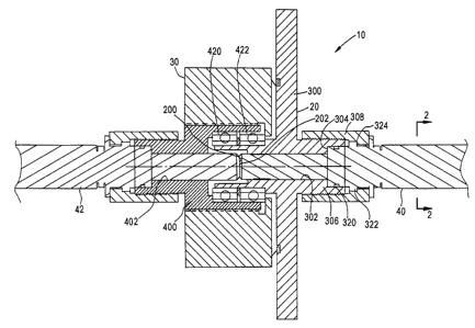
Referring first to Figure l, a multiple channel fiber optic rotary joint,
generally indicated at 10, is illustrated. Although the multiple channel fiber
optic
rotary joint 10 is depicted in a horizontal orientation in Figure 1, it should
be
understood that joint 10 is usable in any orientation. The fiber optical
rotary joint
10 includes a stator assembly 20 and a rotor assembly 30. A fiber optic
connector
40 according to the present invention is housed in the stator assembly 20. A
fiber
optic connector 42 according to the present invention is housed in the rotor
assembly 30. A typical cable usable with the present invention would have two
fiber optic connectors (for example, fiber optic connector 40 on one end
thereof
CA 02341293 2001-03-20
and a fiber optic connector 42 on the opposite end). Of course, any
combination
of connectors 40, 42 can be used.
The construction of the fiber optic connectors 40, 42 is described in
relation to Figures 2 and 3. Connectors 40, 42 can be identical or can be
slightly
5 different depending upon mounting configurations. Either connector 40, 42
can
be the transmitter or receiver and because of the separate channel, signals
can be
transmitted in both directions. Opto-electronics (not shown) are provided to
convert the optical signals carned on each of the multiple optical channels
into
electrical signals in a known manner. The components of the rotor 30 and the
stator 40 are conventional and will be described in detail after the inventive
fiber
optic connectors 40, 42 have been described in detail. The construction of the
optical channels and the size thereof for connectors 40, 42 will be identical
for
any particular rotary joint 10 as explained in detail below. For example, the
inner
and outer diameters of each of the optical channels in each connector 40, 42
will
be identical and in alignment to prevent cross-talk and back reflection.
Referring now to Figure 2, a cross-sectional view of an exemplary fiber
optic connector 40, 42 is depicted. As depicted in Figure 2, a center fiber
100 is
centrally located. This center fiber 100 forms optical channel A. The center
fiber
100 is 125 microns (.0049 in.) in diameter or 240 microns (.0095 in.) in
diameter
and is made of glass or plastic fiber which could also be used. Surrounding
the
center fiber 100 is a separator ring 110 formed of an optically non-conductive
material such as aluminum, glass filled epoxy or steel. The separator ring
must be
sufficiently thick to prevent cross-talk and back reflection between adjacent
channels.
Surrounding the separator ring 110 is a first optical ring formed of .001
inch diameter optical fibers 115 made from preferably glass. The fibers 115
are
placed around the separator ring in a mold to form a first optical ring 120
forming
optical channel B. When enough optical fibers have been placed around the
separator ring 110 another separator ring is placed around the first optical
ring
CA 02341293 2001-03-20
6
120. Fibers could also be plastic and are bonded together by the epoxy.
Additional channels are similarly formed. For example, as depicted in Figure
2, a
third optical channel is formed of a second optical ring 140. A separator ring
145
surrounds the second optical ring 140. A fourth optical channel is formed of a
third optical ring 150. A metal sleeve 155 surrounds the third optical ring.
Each
of the rings and separator layers can be co-extensive. Similarly, a second
optical
ring 135 is formed of a plurality of optical fibers 130. After the second
optical
ring 135 has been formed, another separator layer 140 is placed around the
second
optical ring 135. Additional optical rings can be formed as necessary. The
metal
sleeve 155 is placed around the optical ring 150. The number of channels
formed
can be varied depending on the application. Although four optical channels are
depicted in Figure 2, any number of optical channels can be formed according
to
the present invention.
As depicted in Figure 3, the optical connectors 40, 42 are shown in an
exploded cross-sectional view taken from Figure 1. As depicted in Figure 3,
the
connector 42 has an optical face 200 spaced a distance between 0.001 and 0.003
inches from an optical face 202 of the connector 40. Each connector 40, 42 has
the same configuration for the optical rings and separator rings so that the
optical
rings are in alignment with each other. The optical faces are polished flat in
an
aluminum oxide slurry. This procedure is typical for all optical connectors
throughout the optical industry. The alignment is maintained with the mold
from
0.0005. Axial alignment is maintained to 0.0005 inches.
Returning to Figure 1, an otherwise conventional stator 20 and rotor 30 is
depicted. The stator 20 includes a flange member 300 having an inner bore 302
into which the connector 40 is positioned. The inner bore includes a shoulder
304
against which a portion of the optical connector 40 abuts. A rear portion of
the
flange member 300 has a threaded portion 306 for engaging with a threaded nut
308. The connector 40 has a front shoulder 320 for engaging with shoulder 304
of flange 300 and the connector 40 has a rear shoulder 322 for engaging with a
CA 02341293 2001-03-20
7
shoulder 324 in the threaded nut 308. Thus, the connector 40 is retained
between
flange 300 and the nut 308. The shoulders on the connectors are machined on a
lathe. The entire connector can be machined from steel, aluminum, brass, etc.
The rotor assembly 30 includes a rotor body 400 having a through bore
402. The rotor body 400 has a cavity for receiving a pair of bearings 420, 422
which have an outer diameter in contact with an inner diameter of rotor body
400
and an inner diameter in contact with a portion of flange 300. Thus, the rotor
30
can rotate relative to the stator 20. The optical surfaces 200 and 202 are not
in
contact. A gap of .001-.003 inches exists between the surfaces. The flanges
322
and 324 are machined.
As depicted in Figure 3, each of the rings and layers is aligned between
connector 40 and 42. For example, center fiber 100 is aligned between
connectors 40 and 42. Also, for example, separator ring 125 is aligned between
connectors 40 and 42. Each optical ring provides a signal to an individual
1 S connector which may go to a transmitter or receiver.
As depicted in Figure 4, the fiber 100 is installed in the optically non-
conductive tube or separator ring 110. The fiber 100 is in place inside the
tube
110. The epoxied fiber 100 and ring 110 are then placed into a mold 500
depicted
in Figure SA. The mold 500 has a through bore S 10 having a diameter ~B.
The second non-conductive tube or separator ring 125 is installed
concentric to fiber 100 with a calculated number of 0.001 inch diameter fibers
130
installed in the tube 125 as depicted in Figure 6. This assembly is then
installed
in the mold 500. This mold configuration 500 allows the channels (A and B) to
be concentric to eliminate optical cross-talk and optical signal variation as
the
joints rotates through 360°. For channel C, etc., the mold grows in
diameter. ~A
becomes ~B and ~C is the diameter of the non-conductive tube for channels as
depicted in Figure 7.
In operation, the optical faces 200, 202 are in optical contact with one
another. Optical signals are transmitted through each of the optical channels.
For
CA 02341293 2001-03-20
g
example, and optical signal is transmitted on a first channel through center
fiber
100. A second optical signal is transmitted through the first optical ring
120. A
third optical signal is transmitted through the second optical ring 135. A
fourth
optical signal can be transmitted through optical rings 150. During operation,
connector 42 is rotated relative to connector 40. Because of the close
alignment
between the rings, sleeves and fibers, and the separator rings, there is no
cross-
talk or back reflection and multiple optical signals are carried on each of
the
optical channels. Each of the optical rings or fiber carries a separate
optical
channel.
It should now be apparent that an optical cable has been described having
separate multiple optical channels. It should also be apparent that an optical
connector has been described having separate multiple channels. Also a method
of forming an optical connector and an optical cable has been described having
separate optical channels. Also, a multiple channel on-axis fiber optic rotary
joint
1 S has been described using the inventive optical connector and/or optical
cable of
the present invention.
It will be readily seen by one of ordinary skill in the art that the present
invention fulfills all of the objects set forth above. After reading the
foregoing
specification, one of ordinary skill will be able to affect various changes,
substitutions of equivalents and various other aspects of the invention as
broadly
disclosed herein. It is therefore intended that the protection granted hereon
be
limited only by the definition contained in the appended claims and
equivalents
thereof.