Note: Descriptions are shown in the official language in which they were submitted.
CA 02341437 2001-02-21
WO 00/12888 PCT/US99/19772
FUEL SUPPLY SYSTEM FOR A VEHICLE INCLUDING
A VAPORIZATION DEVICE FOR CONVERTING
FUEL AND WATER INTO HYDROGEN
BACKGROUND OF THE INVENTION
The present invention generally relates to a fuel supply system for a vehicle
aid
more particularly to a system supplying fuel to an internal combustion engine
or fuel cell
of an automotive vehicle.
Ever since the advent of automotive vehicles, those who design and manufacture
automotive vehicles have had the goal of producing a propulsion system that
minimizes
use of fossil fuels and does not generate byproducts that are harmful to
humans or the
environment. The majority of conventional automotive vehicles include an
internal
combustion engine that is fueled by gasoline or diesel fuel. These automotive
vehicles
generally can travel relatively significant distances between refueling and
can obtain up
to about 50 miles per gallon of gasoline. Typically, however, such fuel
economy can
only be achieved at the expense of power and size of the vehicle. Also,
conventional
internal combustion engines contribute significant amounts of pollution to the
environment, particularly in large cities where there are many vehicles on the
road.
Further, the exhaust from these engines includes dangerous levels of carbon
monoxide.
One approach to solve some of the above problems is to feed the supply of fuel
through a vaporization device so as to vaporize the fuel prior to introducing
it to the
internal combustion engine. By first vaporizing the fuel, greater fuel economy
can be
obtained while reducing harmful exhaust emissions. Examples of such
vaporization
devices are disclosed in commonly assigned U.S. Patent Nos. 5,123,398 and
5,666,929.
It was believed that the fuel burns more efficiently and completely when
introduced to
the engine as vapor. One problem experienced with the use of such vaporization
devices
is that the spark plugs, engine cylinders, and valves would quickly become
blackened
with soot, which was believed to be carbon.
An alternative approach to solving the above environmental problems with
internal combustion engines is to power the vehicles with an electric motor.
Electricity
to drive the motor is supplied from a number of batteries in a true electric
vehicle. A
problem with such electric vehicles is that they do not have the range of a
vehicle
powered by an internal combustion engine. Also, the batteries rnay take a
relatively
long time to recharge. Because people have grown accustomed to the greater
range and
-1-
CA 02341437 2001-02-21
WO 00/1288$ PCT/US99/~ 9772
refueling convenience of vehicles powered with internal combustion engines,
electric
vehicles have not been widely accepted by the public.
To increase the range of a vehicle powered with an electric motor, a hybrid
electric vehicle has been developed. In a hybrid electric vehicle, a small
internal
combustion engine is provided to run an alternator that recharges the
batteries as the
vehicle is being driven. In some forms of hybrid electric vehicles, both the
batteries and
the alternator driven by the small internal combustion engine, power the
electric motor.
Because the internal combustion engine in a hybrid vehicle need only drive the
alternator
at a constant speed, the engine may be much smaller and lighter than a
conventional
internal combustion engine. While hybrid electric vehicles show much promise,
they
nevertheless still utilize an engine that pollutes the atmosphere and
generates dangerous
levels of carbon monoxide.
Another type of system for powering a vehicle utilizes a fuel cell. Fuel cells
consume a constant supply of fuel to generate electricity for driving an
electric motor.
Typical fuel cells include an anode and a cathode and operate by feeding a
supply of
hydrogen through a separator membrane between the anode and the cathode so as
to
generate electricity through a redox reaction. Fuel cells are drawing a great
deal of
interest because of their fuel economy and their lack of polluting byproducts.
Fuel
supply systems for such fuel cells are known that generate the supply of
hydrogen from
supplies of gasoline and water. However, because fuel supply systems can take
up to
ten minutes to warm up and generate sufficient quantities of hydrogen to fuel
the fuel
cell and hence drive the electric motor, large and expensive batteries must be
provided
in the vehicle to generate sufficient electricity for initial travel following
start-up.
Currently, fuel cells are too expensive for production due to the need for the
expensive
batteries required for start-up.
Another fuel supply system proposed for vehicles is to power internal
combustion
engines with alternative fuels, such as alcohol, ethanol; methane, and
hydrogen, so as to
reduce the presence of environmentally harmful exhaust gasses. The use of
alternative
fuels has not become commercialized, however, due to their requirements that
the
current infrastructure would require change. For example, gas stations would
have to all
change and begin offering these alternative fuels in addition to gasoline
since vehicles
consuming gasoline would still be in existence. Also, alternative fuels such
as methane
and hydrogen are combustible gasses that would have to be stored in a
pressurized
-2-
CA 02341437 2001-02-21
WO 00/12888 PCT/US99/19772
container within the vehicle and, therefore, would pose a severe danger to the
vehicle
occupants.
It has been proposed that internal combustion engines may be run on hydrogen
that is produced by converting hydrocarbon fuel into hydrogen. See, for
example, U.S.
Patent Nos. 3,682,142; 4,476,817; 4,008,692; 4,003,343; 3,920,416; 5,379,728;
5,085,176; 5,207, i 85; 5,092,303; and 5,156,114. In some of these systems,
heat from
the engine exhaust is used to convert the hydrocarbons to hydrogen. Clearly,
such
systems cannot immediately generate hydrogen when the engine is cold or on
ignition
start-up. Some of these systems rely upon an expensive catalyst, such as
platinum, to
convert hydrocarbons to hydrogen. At least one of these systems burns hydrogen
supplied from a pressurized storage tank to supply heat for the conversion.
Again, the
use of such pressurized hydrogen storage tanks is not desirable due to the
hazard it
presents. Additionally, some of these disclosed systems mix steam with the
fuel to
generate hydrogen and reduce pollutants. However, the heat required to produce
steam
from stored water, which may be cold, is not immediately available on cold
engine start-
up.
SUMMARY OF THE INVENTION
Accordingly, an aspect of the present invention is to provide a fuel supply
system
that does not require changes in the current fuel distribution infrastructure
and yet
obtains significantly better fuel economy than vehicles currently available.
It is another
aspect of the present invention to provide a fuel supply system that exhausts
significantly
less carbon monoxide and NOX than conventional internal combustion engines. An
additional aspect of the present invention is to provide a fuel supply system
that may be
used to supply fuel to current internal combustion engines. Yet another aspect
of the
present invention is to provide a fuel supply system that uses widely
available forms of
gasoline or diesel fuel. The fuel supply system of the present invention may
also use
other forms of fuel such as methane, ethane, or alcohol.
It is another aspect of the invention to provide a system for supplying
hydrogen
to an internal combustion engine without requiring pressurized storage of
hydrogen. Yet
another aspect of the invention is to provide a hydrogen fuel delivery system
which
allows immediate start-up of a cold engine and which does not rely upon heat
of the
engine to convert hydrocarbon fuel into hydrogen.
-3-
CA 02341437 2001-02-21
WO 00/12888 PCT/US99/19772
To achieve these and other aspects and advantages, the fuel supply system of
the
present invention as used for an internal combustion engine, comprises a water
supply
for supplying water, an air inlet, a fuel supply for supplying fuel, and a
conversion
device coupled to the water and fuel supplies and the air inlet for generating
hydrogen
from the water and fuel, and supplying the hydrogen to an intake manifold of
the
internal combustion engine. The conversion device includes heating means for
simultaneously heating the water and fuel to a temperature at which the water
and fuel
convert to hydrogen. Successful experimental tests conducted on a prototype
engine
system confirm these objectives.
Another aspect of the present invention is to provide a fuel supply device for
a
fuel cell that can supply hydrogen to the fuel cell immediately upon vehicle
start-up to
thereby eliminate the need for expensive batteries to provide electricity to
the electric
motor while the fuel supply system warms up. Still another aspect of the
present
invention is to provide a fuel supply device for a fuel cell that generates
hydrogen from
gasoline and water. To achieve these and other aspects and advantages, the
fuel supply
apparatus of the present invention as used for supplying fuel to a vehicle
propulsion
system, comprises a vaporization chamber, an inlet nozzle for introducing fine
droplets
of fuel and water into the vaporization chamber, an air inlet for introducing
air into the
vaporization chamber to create turbulence in the chamber, an electrical heater
in the
vaporization chamber for heating the turbulent fuel/water mix at a temperature
that
causes the mix to convert into hydrogen and harmless byproducts, and an outlet
for
supplying the generated hydrogen to the vehicle propulsion system.
These and other features, advantages, and objects of the present invention
will be
further understood and appreciated by those skilled in the art by reference to
the
following specification, claims, and appended drawings.
BRIEF DESCRIPTION OF THE DRAWINGS
In the drawings:
Fig. 1 is a block diagram illustrating an overview of the fuel supply system
of the
present invention as used with any generic propulsion system;
Fig. 2 is an elevationat cross-sectional view of a fuel conversion device
constructed in accordance with a first embodiment of the present invention;
Fig. 3 is an elevational cross-sectional view of a fuel conversion device
constructed in accordance with a second embodiment of the present invention;
-4-
CA 02341437 2001-02-21
WO 00/12888 PCT/US99/19772
Fig, 4 is a schematic block diagram of a combination engine and fuel supply
system including computer processor controls according to the present
invention; and
Fig. 5 is a schematic block diagram of the fuel supply system control
subsystem
according to an alternative embodiment of the present invention.
DETAILED DESCRIPTION OF THE PREFERRED EMBODIMENTS
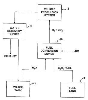
Fig. 1 shows the fuel supply system 1 of the present invention as used with
any
generic vehicle propulsion system 2. As shown, fuel supply system 1 includes a
fuel
tank 3, a water tank 4, a fuel conversion device 10, and an optional water
recovery
device 5. As explained in more detail below, fuel tank 3 and water tank 4 are
coupled to
fuel conversion device 10 to supply both water and fuel continuously in a
predetermined
ratio. Fuel conversion device 10 vaporizes the fuel and water and thereby
generates
hydrogen from the vaporized mix. The output of fuel conversion device 10 is
coupled to
a fuel intake 20 of propulsion system 2 to receive the hydrogen generated by
fuel
conversion device 10.
The inventive fuel supply system 1 may be used to supply hydrogen to any type
of propulsion system capable of running on a supply of hydrogen. Examples of
such
propulsion systems are internal combustion engines and fuel cells. The
contemplated
internal combustion engines with which the inventive fuel supply system may be
used
include those which directly drive the vehicle's wheels and those which drive
an
alternator of a hybrid vehicle. Thus, the inventive fuel system may be used to
supply
fuel to virtually any of today's production internal combustion engines
including diesel
engines, preferably provided that spark plugs are added.
When used to fuel an internal combustion engine, the output of the fuel
conversion device is directly coupled to the intake manifold of the engine.
The vacuum
created by the engine is sufficient to draw the hydrogen out of fuel
conversion device
10. When used to supply hydrogen to a fuel cell, a compressor or some other
device
may be added to pump the hydrogen to the intake of the fuel cell.
The fuel supplied from fuel tank 3 may be any hydrocarbon fuel such as
conventional gasoline, diesel fuel, ethane, alcohol, or methane. Preferably,
the fuel is
one that is already readily available in gas stations. Ideally, the fuel is
gasoline but with
many of the current additives such as anti-knock additives removed, since the
generated
hydrogen does not cause knock and thus does not require an anti-knock
additive.
-5-
CA 02341437 2001-02-21
WO 00/12888 PCT/US99/19772
The water supplied is preferably distilled water so as to eliminate possibly
harmful exhaust byproducts. Because the exhaust of the propulsion system
includes
significant amounts of water vapor when supplied with fuel from the inventive
fuel
supply system, the system may include a water recovery device S such as a
condenser to
convert the water vapor in the exhaust back into water. The recovered water
may be fed
back to water tank 4 for reuse. It is estimated that up to 80 percent of the
water supplied
to fuel conversion device 10 may be recovered from the exhaust of the
propulsion
system. Thus, water tank 4 may be made much smaller and lighter relative to
fuel tank
3 despite the fact that nearly equal amounts of fuel and water are supplied to
fuel
conversion device 10.
The ratio of fuel to water to obtain optimum results depends upon the type of
hydrocarbon fuel used, as apparent from the reaction equations listed below.
In reaction
equation (1), the hydrocarbon fuel was mixed with heat and water vapor to form
hydrogen and carbon monoxide.
Equation 1: CxHY+(X)H20+Heat-~ (X+O.SY)Hz+(X)CO
As shown in reaction equation (2) below, the undesirable carbon monoxide may
be converted to carbon dioxide by exposing it to additional water vapor.
Consequently,
more hydrogen is produced.
Equation 2: CO+Hz0-~COz+Hz
Thus, equation (1) becomes:
Equation 3: CxHY+(2X)Hz0+Heat-~ (2X+O.SY)Hz+(X)COz
Using the prototype system, between slightly less than one gallon to
approximately 1.3 gallons of water was used per each U.S. gallon of unleaded
gasoline.
Such a ratio produces hydrogen on the order of 290,000 ppm, which is well
above the
180,000 ppm level at which hydrogen is combustible. It should be noted that a
greater
ratio of water to gasoline (e.g., up to 1.72 gallons of water per gallon of
gasoline) could
be used in drier climates or conditions and that less water could be used when
the
humidity is high. Because of the effect of humidity, a humidity sensor is
preferably
employed to sense the humidity of the ambient air and a controller may then
regulate the
supply of water based upon the sensed humidity. It should also be noted that
the ratio of
water to fuel will also vary based upon the fuel that is used. For example, if
pentane
(CsH~z) were used, much more water can be added, whereas if propane were used,
much
less water need be added.
-6-
CA 02341437 2001-02-21
WO 00/12888 PCT/US99/19772
Using the fuel conversion device described below, hydrogen may be produced in
sufficient levels using not only gasoline, but also using any other form of
hydrocarbon
fuel, such as diesel fuel, alcohol, methane, or ethane without requiring
significant
modifications to the vehicle. Thus, the present invention affords a much
greater
flexibility than existing fuel supply systems.
Based upon experiments conducted with the prototype engine, the resultant
exhaust gasses consist primarily of carbon dioxide, oxygen, water vapor, and
some
minute amounts of unburned hydrocarbons. Emissions testing of the prototype
vehicle at
1100 rpm and normal engine temperature exhibited HC levels between I3-19 ppm,
Co2
levels between 14.0 and 14.2 percent, NOX levels between 15-22 ppm, CO levels
between 0.03 and 0.12 percent, and 02 levels between 1.8 and 2.2 percent.
Accordingly, the present invention significantly reduces the levels of
pollutants
otherwise exhausted from conventional engines.
The prototype vehicle was further found to start up immediately upon ignition
thereby indicating that hydrogen was being generated immediately upon start-
up. Thus,
the fuel conversion device of the present invention can be used to supply
hydrogen to a
fuel cell immediately upon start-up thereby avoiding the need for pressurized
storage of
hydrogen and expensive batteries to provide electricity to the electric motor
while the
fuel supply warms up, as is the case with other hydrocarbon-to-hydrogen supply
systems
for fuel cells. Further, the device does not rely upon the heat generated by
the engine
itself to produce hydrogen.
Fig. 2 shows the detailed construction of a fuel conversion device 10
according to
a first embodiment of the present invention. The first embodiment as
illustrated,
represents the structure used for a prototype that was constructed and tested
for use with
an internal combustion engine. The prototype was used on a six cylinder engine
in a full
size pick-up truck. Typically, such conventional full size pick-up trucks
obtain fuel
economies of no greater than i5 miles per gallon. With the prototype fuel
conversion
device and the supply of 1.1:128 to 1.5:1 water to fuel ratio, the prototype
system
obtained greatly improved fuel efficiency. Certainly, for a smaller vehicle
and engine,
much greater fuel efficiencies could be obtained.
Referring to Fig. 2, the fuel conversion device 10 is shown to include outer
vertical and horizontal housings 12 and 14 formed from generally cylindrical
bodies
defining the peripheries of the housings. Housings 12 and 14 together define a
fuel,
CA 02341437 2001-02-21
WO 00/12888 PCT/US99/19772
water, and air mixing and gasifying chamber 65, which is here shown to contain
two
interconnected portions. This vertical to horizontal arrangement was to
accommodate
the engine intake manifold of the prototype assembly. Housings 12 and 14 could
be
aligned and could be just one housing forming the one chamber. Within chambers
12
and 14 are heating elements 30 and 32, which provide sufficient heat to
convert a
mixture of small sized (preferably, less than 50 microns in diameter and more
preferably
less than 10 microns in diameter) fuel and water droplets supplied from a
nozzle 60, into
hydrogen. The heating coils 30 and 32 shown in chambers 12 and 14 have a
random
configuration. The fuel/water mixture is preferably transformed by an
endothermic
addition of thermal energy combined with sufficient time converting the
fuel/water
mixture to hydrogen and harmless byproducts. The conversion device includes
heating
means for simultaneously heating the water, air, and fuel to a temperature at
which the
fuel and water convert to hydrogen. In this particular arrangement, the
heating means
includes two heater coils 30 and 32. While this is advantageous, one coil or
more than
two heaters could be used, provided they are controlled as set forth
hereinafter. As used
and described herein, the term "heating means" includes the disclosed heater
coils) and
their equivalents. As stated above, any system or device that heats the
hydrocarbon fuel
with engine exhaust or burning hydrogen supplied from a tank are not
considered
equivalent structures to the disclosed electrical heater coils) due to their
slower cold
starts and requirement for pressurized hydrogen storage.
Housings 12 and 14 are formed to define a vaporization chamber 65 having a
plurality of venturis 64 and 66. Providing the plurality of venturis is
advantageous to
assure turbulence and uniform mixing of fuel, water, and air, particularly
when the
gaseous mixture changes direction. The lower end of housing 12 is attached to
underlying housing 14 by several cap screws 16. A seal between the housings is
formed
by machining an annular male ring 18 fitting into a corresponding annular
female slot
cut into the top of housing 14. Housing 14 serves several functions including
that of 90°
flow transition between primary housing 12 and the conventional internal
combustion
engine intake manifold 20. To aid mounting, an adapter plate 22 is shown
mounted to
the inlet of intake manifold 20 using cap screws 68 recessed beneath the
machined
surface of adapter plate 22. A fuel proof gasket is provided between adapter
plate 22
and housing 14. Long bolts 24 pass through a cover plate 28, housing 14,
adapter plate
22, and lock nuts 26 to secure fuel conversion device 10 to intake manifold
20. Cover
_g_
CA 02341437 2001-02-21
WO 00/12888 PCT/US99/19772
plate 28 is drilled and tapped to receive the connector ends of heating coils
30 and 32
and an optional process temperature sensor 34.
The upstream end of housing 12 is attached by cap screws 36 to transition
housing members 38 and 40. An end cover plate 42.is attached to transition
housing
member 38 with cap screws, retaining an annular air distribution ring 44
securely in
grooves machined into cover plate 42 and housing 12. An outer recess in cover
plate 42
receives a cylindrical nozzle adapter assembly including nozzle 60 and a
nozzle
extension tube 46. Cover plate 42 is drilled and tapped to receive a control
valve 48
(shown schematically) to control ambient combustion air through an inlet 70
for engine
idling. This valued air inlet can also be used for turbo-charged acceleration
air. It could
be used as an alternative to a throttle plate inlet 52 or in conjunction
therewith. Annular
ring 44 is generally cylindrical in cross section, with a series of air inlet
openings around
its periphery. These inlet openings can be circular, as shown, or of other
shape such as
elongated slots. The inflowing air shifts from flowing radially inward to
axially down
around the periphery of axially extending nozzle extension tube 46.
The evenly spaced holes in annular ring 44 have diameters such that the total
cross sectional area, i. e. , of each hole, times the number of holes,
substantially equals
the cross-sectional area of inlet 52 or of a throttle plate 54. The unique
construction of
the annular ring serves to snuff out backfiring.
Upstream of the annular distribution ring 44 and attached to housing 40 is a
cover plate 50. The principal ambient air inlet 52 is in cover plate 50.
Attached to
cover plate 50 directly above inlet 52 is the main throttle body plate
assembly 54 (shown
schematically) for controlling ambient air supply.
The nozzle extension tube 46 adjacent zone 62 serves to both secure nozzle 60
within the device and also act as a barrier to ambient air passage across the
tiny nozzle
discharge droplets until just prior to the throat of venturi 64 and into
turbulent mixing
zone 62 of chamber 65. This barrier function effectively wards off undesired
effects at
the nozzle tip, and promotes decelerated and thorough, even mixing of ambient
air, and
the small sized droplets once the turbulence generated by venturi 64 comes
into play.
The size and shape of the nozzle can vary. The preferred size is about 0.028
inch in
diameter. The preferred spread angle is about 22°. Additionally, nozzle
extension tube
46 works with annular distribution ring 44 in such a manner as to cause
distribution of
ambient air through the evenly spaced, circumferentially arranged holes in
annular
-9-
CA 02341437 2001-02-21
WO 00/12888 PCT/US99/19772
distribution ring 44. Due to the differing distances that different air
molecules have to
travel to reach the distribution holes from the lateral air inlet, coupled
with the lower
pressure environs of an intaking engine cylinder, a turbulent rotating air
mass emerges
from annular ring 44 and comes into mixing contact with the spreading, i.e.,
diverging,
yet dense homogeneous stream of small sized fuel and water droplets emanating
from
nozzle 60, helping to diminish the droplet mass concentration just prior to
the
introduction of additional generated turbulence by the differential pressure
areas
associated with venturi 64. Turbulence is further enhanced by the tumbling
caused by
flow of the mixture through and around coils 30 and 32, along with additional
pressure
differential turbulence at the second venturi 66. The housing taper in the
initial
gasification/mixing housing 12 and downstream of venturi throat 64 are also
preferably
20° to correspond with the spray spread and shape of nozzle 60. Nozzle
60, chosen for
the prototype device because of its spread angle and its capacity in gallons
per hour at
specified differing PSIG air inputs, is preferably a Model SU2A from Spraying
Systems
Co., P.O. Box 7900, Wheaton, Illinois 60189-7900 USA or a Model AL-1 nozzle
from
Delavan Corporation of England. However, many different nozzles could be used
to
deliver small sized droplets of fuel and water. The respective spray pattern
angle would
influence the corresponding taper in, and size of, housing 12. Air from a
dedicated air
pressure source is delivered to the nozzle via an electronic air pressure
regulator with a
preset initial air pressure value and preset pressure range values.
Determination of the
preset initial air pressure to be delivered to the nozzle is dependent on
desired nozzle
fuel and water output. Nozzle output is largely a function of liquid density
and siphon
height or gravity head to the fuel reservoir and air pressure through the
nozzle.
According to the first embodiment, fuel and water are supplied to nozzle 60
from
their respective tanks via two separate supply lines that are connected to the
nozzle inlet
using a Y-adapter. Thus, alternating fuel and water droplets are introduced to
nozzle
60.
Coils 30 and 32 are secured to and have their leads extend through cover plate
28. Also secured to and having its lead extend through cover plate 28 is the
optional
temperature sensor 34. Integrated within coils 30 and 32 are temperature
sensors 56 and
58. A combination of coil types is possible. Heated liquid ( > 140°F)
could be used as a
heat transfer medium in either or both coil 30 and coil 32. Alternatively,
either or both
coils 30 and 32 could be the preferred choice, which is an electrical
resistance heating
-10-
CA 02341437 2001-02-21
WO 00/12888 PCT/US99/19772
coil. Development favored the use of electrical resistance coils with
microprocessor
burst firing control. Three such sensors are shown in Fig. 2. Process
temperature
sensor 34 works in conjunction with the microprocessor controlling the firing
of coils 30
and 32, while sensors 56 and 58 which are an integrated part of coils 30 and
32 act as
sensors which, in combination with power limiters, set high temperature limits
for coils
30 and 32.
As noted previously, housing 14 is shown at 90° to housing 12 to
facilitate the
flow of the gaseous fuel/water mixture from the fuel conversion device 10 to
an existing
internal combustion intake manifold 20. In other applications, housings 12 and
14 could
be arranged linearly or combined as one housing to accommodate physically
different
intake manifold configurations, as described above.
In operation, coils 30 and 32 supply heat. Tiny micron sized fuel and water
droplets and a small amount of air are supplied by nozzle 60. As the engine
turns over,
a partial vacuum within the combustion chamber draws ambient air past idle
control
valve 48 through the distribution holes in annular distribution ring 44 to the
zone or
region 62 past the end of nozzle extension tube 46 where it is entrained with
the dense
flow, small sized fuel and water droplets coming from nozzle 60. Turbulence in
the
ambient air caused by flow through the annular distribution ring 44, augmented
by
turbulence generated by differential pressure associated with venturi 64,
initiates the
mixing of the small sized fuel and water droplets together with ambient idle
air.
Additional turbulence is provided by collision with the downstream coils 30
and 32.
Mixing continues to be aided by pressure differential generated by venturi 66.
As the
fuel/water/air mixture tumbles through the influence of coil 30, thermal
energy is
absorbed both by direct collision with and radiation from coil 30, beginning
the
endothermic reaction leading to the generation of a hydrogen/air mixture.
A fuel conversion device 10' according to a second embodiment of the present
invention is shown in Fig. 3. In Fig. 3, the same reference numerals as used
to
described the first embodiment are used to describe like components of the
second
embodiment. As will be apparent from a comparison of Figs. 2 and 3, the only
difference between the first and second embodiments is that the single inlet
nozzle 60 of
the first embodiment is replaced with a nozzle 60' having two inlets 61a and
62b for
separate connection to the fuel and water tanks. In this manner, the water and
fuel are
-11-
CA 02341437 2001-02-21
WO 00/12888 PCT/US99/19772
not mixed until after they have been injected as small droplets into nozzle
extension tube
46.
The manner in which fuel and air pressure are controlled for supply to nozzle
60
and the manner in which heater coils 30 and 32 are controlled is described
below with
reference to one embodiment of the control system of the present invention as
shown in
Fig. 4 and an alternative embodiment as shown in Fig. 5. The control system
shown in
Fig. 4 represents computerized controls and inverted 120v, AC electrical
circuitry used
to run the prototype conversion device/engine combustion.
Listed by number are the following prototype components used in the first
embodiment of the central subsystem as shown in Fig. 4:
200 Internal combustion engine
Intake manifold of internal combustion engine
204 Engine driven alternator
206 12v DC battery
15 208 Engine driven air pump
210 Check valves
212 Air storage tank
214 Pressure relief valves (2)
216 NC 12v DC solenoid
20 218 NC 12v DC continuous duty solenoid (2)
220 Ignition switch
222 Auxiliary air pump
3 Fuel tank
4 Water tank
226 Fuel pump
227 Water pump
228 Fuel metering device
229 Water metering device
230 Idle fuel conduit
231 Idle water conduit
232 Run fuel conduit
233 Run water conduit
-12-
CA 02341437 2001-02-21
WO 00/12888 PCT/US99/19772
60 Nozzle (SU2A Spraying Systems Co., Wheaton, Illinois or AL-1 Delavan
Corporation,
England)
236 Injector of micron droplet fuel/water/air mixture
54 Ambient air control valve
242 Vacuum diaphragm
244 Piezo-electric device
246 Variable voltage signal
248 Electro-pneumatic pressure regulator from Proportion-Air Inc.,
McCordsville,
Indiana
250 12v DC to 120v AC converter
252 Microprocessor-based Auto Tuning Control from Watlow Controls, Winona,
Minnesota
254 Solid state relay control from Watlow Controls, Winona, Minnesota
256 Temperature limit/Control from Watlow Controls, Winona, Minnesota
258 Air line
30 120v AC cable resistance heater w/internal "J" thermocouple from Watlow
World Headquarters, St. Louis, Missouri
34 "J" thermocouple sensor from Watlow Gorcon, Richmond, Illinois
56 Thermocouple leads from neater coil 30
264 120v AC power lead L1
266 120v AC power lead L2
The controlled quantities of ambient air and tiny fuel and water droplets will
change, often very rapidly, as demands placed upon the internal combustion
engine
change. The more demand placed upon the engine, the more ambient air, fuel and
water
droplets, and thermal energy required. Conversely, lessening demands require
less fuel,
less water, less air, and less thermal energy. Rapidly changing demands, such
as are
experienced when the internal combustion engine is used as a source of power
for an
automotive vehicle, require very rapid response times for control of, in
particular, fuel
and water demands and thermal energy supplied by the heating coils.
Fuel conversion devices as illustrated by the proposed invention require
sophisticated controls to respond quickly and safely to changing engine
demands.
Experience working with the prototype has shown that instantaneous engine
starting, fuel
-13-
CA 02341437 2001-02-21
WO 00/12888 PCT/US99/19772
economy and low emissions require adequate in the endothermic heat of
vaporization
supplied during the fuel conversion process. A steady source of endothermic
heat was
tried and proved to be unacceptably slow in meeting low emission engine
starts. 12v
DC heat sources were attempted but proved to also be slow in providing
sufficient
S thermal output to complete fuel conversion during high engine demand, due to
unacceptably high amperage demands on the 12v DC system. 120v AC, 220v AC and
440v AC resistance heaters were known to provide sufficient thermal output,
but were
initially thought to perhaps be too uncontrollable.
Design criteria called for finite control of fuel and water droplets
regardless of
engine performance demands. The resultant solution called for finite control
of small
sized fuel and water droplets coupled with finite control of heat of
vaporization.
Microprocessor controls were therefore provided to meet finite control and
safety.
Thermal energy supplied to the fuel conversion device to provide endothermic
heat of vaporization results from distributed wattage along the two cable
heaters 30 and
1S 32 within the gasification chamber. These resistance heaters operate at
120v AC and are
capable of attaining 1100° F interior temperatures and equally hot
surface temperatures
within seconds of receiving power. Limiting supplied voltage results in
temperature
control so that safety limits are not exceeded, but also limits BTU output
when less heat
of vaporization is needed. Control of thermal energy at needed but safe levels
is
achieved by monitoring the temperature within vaporization chamber 6S. Safety
limits
are assured by placing a temperature limit controller 2S6 in series between
the power
source 2S0 and the solid state firing relay 254. The temperature limit control
2S6
receives input from "J" thermocouple sensors S6 and S8, which measure internal
coil
temperatures and are embedded within resistance coils 30 and 32, respectively.
Preset
2S limits within the control 2S6 are compared to actual coil temperatures, and
if exceeded,
power is denied to the firing relay 2S4 and to the coil until coil temperature
drops below
the preset safety temperature. Thus, microprocessor power controls keep coil
temperatures within safety limits.
If preset temperature limit safety criteria are met, power is supplied to the
firing
relay 254. The auto tuning control 2S2 determines how long the coil 30 is to
be fired
(duration) at full power to achieve a process temperature set in the auto
tuner 252, which
is compared to input temperature from a "J" thermocouple sensor 34 inserted
near the
end of the vaporization chamber within fuel conversion device 10. The solid
state firing
-14-
CA 02341437 2001-02-21
WO 00/12888 PCT/US99/19772
relay burst fires the coil at the zero point on the sinusoidal wave associated
with 120v
AC 60 cycle current. This zero firing effectively controls temperature
overshoots and
adds tremendously to the life of the resistance heaters. The thermal process
temperature
set into auto tuner 252 may be set to reflect driving demands (i. e. , load
and ambient
outside air conditions).
Temperature sensor 34 senses the temperature of the combustion mixture of
small
sized fuel and water droplets introduced into gasification housing 12 through
inlet
conduit 46 and entrained with ambient air passing through annular air
distribution ring
44 from inlet air controls 54 and 48 and turbulence zone 62. Temperature
sensor 34
supplies the sensed temperature of the combustion mixture to the
microprocessor in auto
tuning control device 252. The microprocessor compares this sensed temperature
to a
preprogrammed default temperature of, for example, a temperature in the range
of 100
to 225°F, and outputs a 4-20 mA signal to a microprocessor in a firing
relay control
254, which time proportions the electrical current passed through resistance
coils 30 and
32. The turbulent mixture of ambient air and tiny fuel and water droplets
absorbs
thermal energy from coils 30 and 32, through radiation and/or through direct
collision
with coils 30 and 32, sufficient to complete the vaporization and conversion
to hydrogen
prior to entering engine intake manifold 20.
The fuel and water droplets are introduced by an injector, preferably nozzle
60,
with the aid of a small amount of air called "assist air. " Pressure increases
in nozzle air
will cause a corresponding increase of fuel from a metered source 228. To
facilitate
changes in air pressure to meet changing engine fuel needs, the direct
relationship
between engine load and engine vacuum is utilized. Greater load creates less
engine
vacuum. Conversely, lessening loads increase vacuum. A vacuum diaphragm 242
attached to a resistance spring operates a mechanical linkage attached to a
piezo-electric
device 244. Vacuum increases decrease the variable voltage generated by piezo-
electric
device 244. Conversely, dropping engine vacuum (under load) causes increasing
variable voltages. The variable voltage operates as a signal 246 to an electro-
pneumatic
air pressure regulator 248 having a microprocessor, which regulates air
pressure
dependent upon input voltage signals 246 from piezo-electric device 244. An
initial set
point and total pressure range preset in the microprocessor of electro-
pneumatic air
pressure regulator 248 allow for variable pressure changes to nozzle 60 to be
dependent
upon engine loading. Throttle position and change in throttle movement, both
in
-15-
CA 02341437 2001-02-21
WO 00/12888 PCT/US99/19772
direction and speed, could be translated as input signals to provide even more
finite
control of assist air, as illustrated in Fig. 5 and described in greater
detail below. These
components are more specifically described hereinafter.
Referring specifically to the schematic diagram in Fig. 4, fuel is delivered
to a
fuel metering device 228 from fuel tank 3 using a positive pressure fuel pump
226. The
fuel pump may be dependent upon nozzle injector 60 to be of either constant or
variable
pressure. Dependent upon nozzle injector 60 type and engine idle demand, idle
fuel may
have to be metered and supplied through conduit 230 independent of power
engine
demands. Increased demand for fuel may require additional metering of fuel
through
parallel conduit 232. Similarly, water is delivered to a water metering device
229 from
water tank 4 using a water pump 227. Again, the water pump may be dependent
upon
nozzle injector 60 to be of either constant or variable pressure. Depending
upon nozzle
injector 60 type and engine idle demand, idle water may have to be metered and
supplied
through conduit 231 independent of power engine demands. Increased demand for
water
may require additional metering of water through a parallel conduit 233.
In the prototype, nozzle injector 60 of external mix siphon feed was chosen
for
its small micron-sized liquid droplet performance characteristics. Such a
nozzle requires
a small amount of air to accomplish the production of small micron fuel and
water
droplets. Many other nozzle types using changing liquid pressure, with or
without air
assistance, to mechanically produce small droplets, could be used. Air to
assist in
nozzle injector functioning is supplied from an air tank 212 with its
pertinent filtration
and pressure relief valve 214. This air supply is controlled as on or off by a
12v DC
solenoid valve 216 wired to the ignition switch. Air supply to air tank 212 is
provided
by an auxiliary air pump 222 or, if the engine is running, by an engine driven
air pump
208.
When the ignition is turned on, circuits are opened allowing air passage from
the
tank through solenoid 216 to the electro-pneumatic pressure regulator 248.
This device
allows for changing air pressure to nozzle injector 60. A variable voltage
and/or milli-
amp signal in line 246 (the prototype uses variable voltage 0-lOv DC) is
generated by
piezo-electric device 244 coupled to a vacuum diaphragm 242, which is in turn
connected to the intake manifold 20. Once the engine has fired and remains at
idle,
vacuum diaphragm 242 resists spring tension to influence the piezo-electric
device 244,
sending a steady signal to the electro-pneumatic regulator 248 which has been
set to
-16-
CA 02341437 2001-02-21
WO 00/12888 PCT/US99/I9772
supply, together with metered fuel in conduit 230 and metered water in conduit
231, the
precise amount of air necessary to provide a very lean, low-pollution-
producing
hydrogen/air mixture delivered to fuel conversion device 10. Once engine
demand
changes as during acceleration, a resultant instantaneous drop in engine
vacuum occurs,
causing the spring in vacuum diaphragm 242 to advance the movement of the
sliding
wire in piezo-electric device 244, which in turn instantaneously increases the
voltage
signal to electro-pneumatic pressure regulator 248, allowing for an increase
in air
pressure to nozzle-injector 60 facilitating increased fuel and water flow.
Engine demand
changes could also be initiated by throttle valve 54 changes or load changes,
such as are
experienced when automotive vehicles go up or down a hill. Experience has
shown that
additional input from device 244 associated with throttle movement, throttle
speed, and
throttle position helps to fine-tune the fuel delivery system.
Opening and closing ambient air control valves 48 and 54 initiates immediate
changes in engine vacuum, which is reflected by changes in the amount of fuel
and water
droplets generated by nozzle 60. Decreasing engine demand leads to decreases
in the
amount of fuel and water delivered. Less fuel and water passing through coils
30 and 32
require less energy for the mixture to remain at a preset mixture temperature
as sensed
by sensor 34. Excess thermal energy causes an increase in mixture temperature,
which
triggers a change in the sensor 34 signal to the computer. Deviation upward
from the
preset default temperature, which may be between 100 to 225°F, for
example, causes a
signal change to the firing control relay 254 causing a time-proportional slow
down in
the energizing of the electrical resistance coils 30 and 32, resulting in
lower coil
temperatures with less thermal output. Should coil temperatures reach a safety
temperature maximum, signals generated continuously by sensors 56 and 58 would
activate circuitry in temperature limit controls 256 to interrupt power flow
to coils 30
and 32.
The preferred embodiment of the fuel conversion device thus provides one or
more devices for injecting small micron sized fuel and water droplets, means
to entrain
the fuel and water droplets with ambient air, and a vaporization chamber
together with
heating coils for vaporizing the entrained fuel/water mixture to generate
hydrogen.
These components could include physical shape variations to accommodate
differing
engine intake requirements. The preferred components illustrated in Fig. 4 as
reflecting
the prototype employs computer control of fuel delivery and heating coil
performance.
-17-
CA 02341437 2001-02-21
WO 00/12888 PCT/US99/19772
The fuel conversion device can be built to perform safely using mechanical
controls,
liquid heat mediums within the coils and standard, off-the-shelf explosion-
proof
solenoids. The prototype uses various segregated microprocessors to control
fuel flow
and heating coil thermal output. An inverter 250 changing 12v DC current to
120v AC
S current maximizes heating coil performance. Treating the gasification
process as a
thermal process utilizing microprocessor controlled, electrical resistance
heaters,
together with temperature limit controllers, assures safe, efficient,
responsive heating
coil performance.
The fuel conversion process is further aided as the mixture continues past
coil 32.
The resulting hydrogen, which arrives at the combustion chamber, provides more
complete combustion than today's carburetor and injector fuel-air mixtures.
Experimentation has shown that the engine fires immediately and continues to
run
smoothly. Changes in engine demand are reflected as changes in fuel/water/air
demand.
Providing sufficient engine power to accelerate requires increased engine
rpms.
Specifically, the throttle plate 54 is opened for increased air flow, causing
a decrease in
engine vacuum. These engine vacuum changes acted upon the vacuum diaphragm 242
causing mechanical diaphragm movement, which is translated by piezo-electric
device
244 into a changing voltage signal sent to electro-pneumatic regulator 248.
Electro-
pneumatic regulator 248 through its microprocessor, using preset initial
pressure and
pressure range, regulates air pressure output from a high pressure storage
tank 212.
Increased engine demand such as is experienced during acceleration is
accompanied by
an immediate decrease in engine vacuum. Combining a vacuum diaphragm 242
coupled
to a piezo-electric sliding wire device 244 provides an immediate variable
input signal to
electro-pneumatic pressure regulator 248 indicative of engine demand, as
reflected by
engine vacuum. Engine vacuum decreases are reflected as fuel increases. As
automotive vehicle momentum change rates are met, less fuel and water are
required to
maintain established momentum. Less engine demand provides greater engine
vacuum,
less air pressure to nozzle 60, and decreased fuel and water requirements.
Fig. 5 shows an alternative embodiment of the control subsystem of the present
invention. Control of the inventive fuel conversion device 10 is safely and
efficiently
performed by a fast (preferably 32 bit architecture) central processing unit
(CPU) 76
receiving thermal inputs 80, exhaust inputs 82, ambient air inputs 84, engine
inputs 86,
fuel inputs 88, water inputs 89, and assist air inputs 90. Thus, the various
segregated
-18-
CA 02341437 2001-02-21
WO 00/12888 PCT/US99/19772
microprocessor functions of the first embodiment may be embodied and performed
by a
single CPU 76. CPU 76 generates and supplies an output control signal to
heater firing
relay 94 and temperature Iimiter 92 efficiently for safely firing heaters 30
and 32.
Additional CPU output control signals are supplied to electronic controllers
96 and 98
S (Figs. 2 and 5), which in turn regulate fuel and water flow rates to
injector nozzle 60.
Ambient air inlet control valve 54 receives another control signal output by
CPU 76 to
complete the control and management of ambient air, fuel, water, and thermal
energy
embodied in conversion device 10 to power internal combustion engine 100.
Inputs
from sensors 34, 56 and 58 in combination with other pertinent data, as
illustrated in
Fig. 5, are digitally processed to heat generation by coils 30 and 32
regardless of engine
demands and/or ambient air temperature/pressure changes.
As illustrated in Fig. 5, in addition to signals generated by devices coupled
to
engine vacuum, signals reflecting throttle position, throttle position change
rate, outside
air temperature, barometric pressure and engine operating temperature could,
in
combination with coil temperature inputs and process temperature inputs, be
computed
by CPU 76 or a "fuzzy logic" board to provide immediate finite control
signals. These
outputs sent to controllers would insure maximization of performance and
economy
while simultaneously minimizing exhaust pollutants.
Another possible method of process control would include additional inputs and
fuzzy logic control outputs to firing and limit controls. Variables such as,
but not
limited to, relative humidity, fuel type or composition, throttle movement,
coolant
temperature, cylinder head temperature, exhaust gas temperature, manifold
vacuum, and
density altitude would, if inputted to a fuzzy logic board, allow for outputs
to controllers
capable of infinite adjustments to the fuel conversion device. Such infinite
control would
shorten response time, increase engine power, and keep pollutants at a very
low level
regardless of engine demands.
These and various other modifications could be made to the illustrated and
presently preferred embodiments depicted without departing from the inventive
concept.
Therefore, the invention is not intended to be limited to the illustrated
embodiments
shown, but only by the scope of the appended claims and the equivalents
thereto.
-19-