Note: Descriptions are shown in the official language in which they were submitted.
CA 02341465 2001-02-21
PCT/CN99/00088
Amended sheet (Upon Article 19)
Purely Rolling Bearing
Technical Field
This invention relates to a rolling bearing, particularly to such a purely
rolling bearing
without sliding friction.
Background of the Invention
The usual rolling bearing comprises an inner race ring and an outer race ring,
a number of
rolling members and a retainer. The retainer is provided in the bearing for
the rolling
members to locate each other and for the relative location of the rolling
bodies in the
bearing. The rolling members are restricted at high speed by the said retainer
because of
sliding friction, no matter what structure or what material and smooth finish.
The sliding
friction resistance influences seriously the properties and life of a bearing.
The relative sliding friction between the rolling members and retainer will
cause a series of
problems while the bearing is running, especially at high speed, such as it is
difficult to be
lubricated, the temperature rising increases, the noise is heightened. Under
the conditions
of high temperature and high speed, the stress will increase suddenly which
results in ruin
of the bearing. The rolling friction resistance in a bearing is not worth
mentioning
compared with the sliding friction resistance. The existing of the sliding
friction causes that
the load capacity of the rolling bearing is obviously reduced and the energy
loss is
remarkable. At high speed, the sliding friction force produced by the action
of the
centrifugal force between the rolling members and the retainer will increase
notably. The
friction stress concentration will bring about the ruin of the bearing
rapidly. Consequently,
the raise of the limited speed of the rolling bearing is confined with the
sliding friction.
US patent 3,124,396 discloses a kind of rolling bearing, which uses rolling
separators
similar to cylinder instead of the retainer, and uses retaining rings to hold
and retain the
related rolling separators, so that the bearing could become a positive
rolling bearing. But,
the retaining ring comprises an outer ring, an inner split spring ring and a
wire locking ring,
CA 02341465 2001-02-21
PCT/CN99/00088
Amended sheet (Upon Article 19)
therefore, the structure of the bearing is complicated, the cost is higher and
the assembly is
more difficult. Besides the foregoing problems, the inner split spring ring is
provided with
a scarf. There must be a crack, namely there is distance between the opposite
ends. When
any one of the rolling balls arnves at the crack, the vibration, disturbance
and wear will be
produced. In addition, the friction between the retaining rings and the two
opposite ends of
any one of the rolling separators are still sliding friction, which influence
the properties of
the rolling bearing.
European patent 0,264,264 revealed another kind of rolling bearing, which
provides a
roller (that is a rolling retainer member) similar to a cylinder to replace
the usual retainer.
t0 The rollers are assembled and sustained by using of location rings. But,
the location rings
of the rolling bearing must comprise two free ring members 5 and two
supporting rails 6a
which are used to sustain the location rolling bodies along the opposite
radial directions,
respectively because any one of the rollers is an-anged to insure its axis to
be located on the
center of the connecting line between the two adjacent rolling ball centers.
(See Fig. 2 of
the referenced patent). Therefore, its structure is complicated, its cost is
high and the
assembly is difficult. In addition, the friction between the location rings
and the two
opposite ends of the rollers is still sliding friction, which influence the
properties of the
bearing.
Besides the above, the contact between the cylinder positioning rolling member
(roller)
and the rolling member ( ball ) is the contact of the two sections of circular
in two patents
as mentioned above. If the arc curvature radius of the positioning rolling
member is larger
than the curvature radius of the rolling member, the contact is single point
contact, then
which makes the rolling members incline and be unstable. If the arc curvature
radius of the
positioning rolling member is less than the curvature radius of the rolling
member, the
contact is a two point contact, thus causing the rolling bodies wear and tear
easily, and lose
efficacy at last.
Summary of the Invention
The object of the invention is to provide a purely rolling bearing, which is
in a simple
structure and easy to be assembled.
2
CA 02341465 2001-02-21
PCT/CN99/00088
Amended sheet (Upon Article 19)
In order to realize the above object, the invention provides a purely rolling
bearing which
comprises an inner race ring, an outer race ring, a number of rolling members
between the
inner race ring and the outer race ring, positioning rolling members arranged
in alternation
with the rolling members and kept in rolling contact with the balls, and a
positioning ring
arranged on the race ways of the two ends of the positioning rolling members,
wherein, the
related positioning rings are all made up of unitary part, and in the rolling
contact with the
raceways.
The invention is put forward as follows:
Each positioning rolling member is assembled between the two adjacent rolling
members.
The positioning rolling members insure simultaneously uniform circumferential
spacing of
the adjacent rolling members and confine the rolling members to axial location
in the
bearing. The axial and radial location of the positioning rolling members are
restricted by
the positioning rings on the raceways of the two opposite ends of the
positioning rolling
members. The contacts between the positioning rings and any raceway of the
positioning
rolling members are point contacts, and so are the point contacts between any
one of the
positioning rolling member and the adjacent rolling member. The movements of
the
positioning rolling members include a self rotation and a revolution round the
axis of the
bearing. The relative velocity difference between a contact point on any one
of the location
rolling bodies and the contact point on the rolling body contacted, both of
which coincide
each other, is zero, and so is the relative velocity difference between a
contact point on
either of the location rings and the contact point on the location rolling
body contacted,
both of which coincide each other. Therefore, those movements of the contact
points all
belong to purely rolling movements. There is not any relatively sliding
friction. The
bearing is a purely rolling bearing, which name matches reality. The assembly
and
production of the bearing of the invention are easy. So the invention could be
extended and
applied easily and widely.
The following will further describe in detail the invention in combination
with a preferred
embodiment together with the figures attached.
Brief Description of the Drawings
3
CA 02341465 2001-02-21
PCT/CN99/00088
Amended sheet (Upon Article 19)
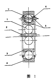
Fig. 1 is the radial section view of a rolling bearing of the invention.
Detailed Description of the Preferred Embodiments
Please refer to Fig.I, each positioning rolling member 2 is assembled between
two adjacent
rolling members 1 and along the circumferential direction. The positioning
rolling
members 2 insure simultaneously uniform circumferential spacing between two
adjacent
rolling members 1 and confine the rolling members to the axial location in the
bearing. The
axial location and radial location of the positioning rolling members are
performed by
positioning rings 6 on the raceways 5, which is a circular arc in cross
section, of two
l0 opposite ends of the positioning rolling members. The contacts between
either of the
location rings 6 and any one of the raceways 5, any one of the location
rolling bodies 2 and
the rolling body 1 contacted and any one of the rolling bodies 1 and the inner
race ring 3 or
the outer race ring 4 of the bearing are all point contacts, and the relative
velocity
differences between any two points contacted with each other are all zero.
Therefore the
bearing is a purely rolling bearing.
The cross section of the raceway 5 is concave shape, the cross section of the
positioning
ring 6 is a convex shape, so that they form a rolling contact. On the
contrary, let the cross
section of the raceway 5 be a convex shape and the cross section of the
positioning ring 6
be a concave shape, it is feasible too. In addition, the cross section of the
raceway 5 and the
central raceway 7 of any of the positioning rolling member 2 contacted with
the rolling
member 1 may be V-shaped, circular-arc-shaped or notch-shaped, and so on. The
cross
sections of the raceway of the inner race ring 3 and the outer race ring 4 may
also be V-
shaped, circular-arc-shaped or notch-shaped, and so on.
The positioning rolling member 2 may be made into parted parts, for the
convenience of
the assembly and production. That is, the two parts which form the two
opposite end
raceways 5 and the part which forms the central raceway 7 may be produced
separately
first, then be fixed through the tight fit or screw fit and so on. Of cause,
the positioning
rolling member 2 may be made into a single part.
A variety of equivalent variations may be made by the technicians familiar
with the
technical realm on the basic of the invention, although the invention has been
described
4
CA 02341465 2001-02-21
PCT/CN99/00088
Amended sheet (Upon Article 19)
above combined with a preferred embodiment. Therefore, the scope of the
invention
should be defined by the claims.