Language selection

Search

Patent 2342069 Summary

Third-party information liability

Some of the information on this Web page has been provided by external sources. The Government of Canada is not responsible for the accuracy, reliability or currency of the information supplied by external sources. Users wishing to rely upon this information should consult directly with the source of the information. Content provided by external sources is not subject to official languages, privacy and accessibility requirements.

Claims and Abstract availability

Any discrepancies in the text and image of the Claims and Abstract are due to differing posting times. Text of the Claims and Abstract are posted:

  • At the time the application is open to public inspection;
  • At the time of issue of the patent (grant).
(12) Patent Application: (11) CA 2342069
(54) English Title: AIR POWERED HYDRAULIC JACK WITH LOAD SENSING AUTO SHUT-OFF AIR CONTROL
(54) French Title: VERIN HYDRAULIQUE A COMMANDE PNEUMATIQUE A ARRET AUTOMATIQUE SENSIBLE A LA CHARGE
Status: Deemed Abandoned and Beyond the Period of Reinstatement - Pending Response to Notice of Disregarded Communication
Bibliographic Data
(51) International Patent Classification (IPC):
  • F15B 13/042 (2006.01)
  • F04B 17/00 (2006.01)
  • F04B 49/02 (2006.01)
  • F04B 49/08 (2006.01)
  • F15B 11/028 (2006.01)
  • F15B 11/072 (2006.01)
  • F15B 15/00 (2006.01)
(72) Inventors :
  • DECKER, ARNOLD F. (United States of America)
(73) Owners :
  • TEMPLETON, KENLY & CO., INC.
(71) Applicants :
  • TEMPLETON, KENLY & CO., INC. (United States of America)
(74) Agent: MACRAE & CO.
(74) Associate agent:
(45) Issued:
(22) Filed Date: 2001-03-21
(41) Open to Public Inspection: 2001-09-22
Availability of licence: N/A
Dedicated to the Public: N/A
(25) Language of filing: English

Patent Cooperation Treaty (PCT): No

(30) Application Priority Data:
Application No. Country/Territory Date
09/533,416 (United States of America) 2000-03-22

Abstracts

English Abstract


The invention provides an improved fluid motor powered lift system having a
valve arrangement for reducing or interrupting the fluid flow supplied to the
motor when
the pressure in the lift system exceeds a predetermined pressure. A valve
arrangement is
provided to shut-off or throttle back the fluid supplied to the fluid motor
when the fluid
pressure in the lift reaches a predetermined level. When the pressure in the
lift system
exceeds the predetermined level, pilot pressure is supplied to an automatic
shut-off valve,
and this in turn reduces fluid flow to fluid air motor thereby reducing or
preventing pump
pressure.


Claims

Note: Claims are shown in the official language in which they were submitted.

-5-
I Claim:
1. An air powered hydraulic lift system comprising:
a hydraulic cylinder having at least one fluid port for supply of hydraulic
fluid pressure to the cylinder,
an extensible piston in the cylinder,
a hydraulic fluid pump for selectively supplying fluid under pressure to the
fluid port,
an air pressure driven motor operably connected to the hydraulic fluid
pump to drive the hydraulic fluid pump, and
a control valve for controlling the supply of hydraulic fluid pressure from
the hydraulic fluid pump to the fluid port, and
a valve assembly reducing the supply of air pressure to the air pressure
driven motor when the fluid pressure supplied to the control valve exceeds a
predetermined fluid pressure.
2. An air powered hydraulic lift system as set forth in claim 1, wherein the
valve assembly includes a normally closed pilot operated valve controlling
supply of fluid
pressure to the motor and connected to the fluid pump.
3. An air powered hydraulic lift system as set forth in claim 1, wherein the
normally closed pilot operated valve includes a pilot and wherein the valve
assembly
includes a shutoff control valve.
4. An air powered hydraulic lift system as set forth in claim 1, wherein the
normally closed pilot operated valve is operably connected to the fluid pump
such that
when the hydraulic fluid pressure generated by the fluid pump exceeds a
predetermined
pressure, the normally closed pilot operated valve closes to reduce flow to
the air motor.
5. An air powered hydraulic lift system as set forth in claim 1, and further
including an air motor actuating valve between the air supply and the pilot of
the normally
closed pilot operated valve, the air motor actuating valve including a pilot
actuated by
hydraulic fluid pressure supplied by the fluid pump.

-6-
6. A fluid powered fluid lift system comprising:
a cylinder having at least one fluid port for supply of fluid pressure to the
cylinder,
an extensible piston in the cylinder,
a fluid pump for selectively supplying fluid under pressure to the fluid port,
a fluid pressure driven motor operably connected to the fluid pump to drive
the fluid pump,
a control valve for controlling the supply of fluid pressure from the fluid
pump to the fluid port, and
a valve assembly controlling the supply of fluid pressure to the motor and
reducing the supply of fluid pressure to the motor when the fluid pressure
supplied to the
control valve exceeds a predetermined fluid pressure.
7. A fluid powered lift system as set forth in claim 6, the valve assembly
including a normally closed pilot operated valve controlling supply of fluid
pressure to the
motor and connected to the fluid pump.
8. A fluid powered lift system as set forth in claim 7, the normally closed
pilot
operated valve including a pilot and wherein the valve assembly includes a
shutoff control
valve.

9. An air powered hydraulic lift system comprising:
a hydraulic cylinder having at least one fluid port for supply of hydraulic
fluid pressure to the cylinder,
an extensible piston in the cylinder,
a hydraulic fluid pump for selectively supplying fluid under pressure to the
fluid port,
an air pressure driven motor operably connected to the hydraulic fluid
pump to drive the hydraulic fluid pump, and
a valve assembly for controlling the supply of air pressure to the air
pressure driven motor, the valve assembly including a normally closed valve
shiftable to
an open position in response to manual actuation by an operator, the valve
providing air
flow to the air motor when the valve is shifted to an open position and
interrupting air flow
to the motor when the valve is closed.
10. An air powered hydraulic lift system as set forth in claim 1, wherein the
valve assembly is spaced apart from the hydraulic cylinder to provide a remote
control for
operation of the air motor.

Description

Note: Descriptions are shown in the official language in which they were submitted.


CA 02342069 2001-03-21
AIR POWERED HYDRAULIC JACK
WITH LOAD SENSING AUTO SHUT-OFF AIR CONTROL
FIELD OF THE INVENTION
The invention relates to air powered hydraulic lifting systems and more
particularly
to controls for effecting actuation of such systems.
BACKGROUND PRIOR ART
In hydraulic lift systems it is advantageous in some applications to use an
air
pressure driven motor to drive a hydraulic fluid pump which selectively
supplies hydraulic
fluid pressure to the hydraulic cylinder of the hydraulic lift system. An
example of a prior
art arrangement is illustrated in U.S. Patent No. 4,251,055. Attention is also
directed to
U.S. Patent No. 4,889,472.
In prior art arrangements of such hydraulic lift systems a manually operated
control
valve is provided to control the flow of hydraulic fluid from the pump to the
cylinder. A
pressure relief valve is connected between the pump and the fluid cylinder to
exhaust fluid
to the tank when fluid pressure reaches a predetermined pressure. If the
cylinder reaches
the end of its stroke and the hydraulic pump continues to operate, hydraulic
fluid is
exhausted to the tank through the pressure relief valve to the tank. This can
result in
damaging heat generation in the hydraulic system and destruction or
deterioration of
components of the system such as seals and other non-metallic components.
SUMMARY OF THE INVENTION
The invention provides an improved fluid motor powered fluid lift system
having a
valve arrangement for reducing or interrupting the fluid supplied to the fluid
motor when
the pressure in the lift system exceeds a predetermined pressure.
One of the features of the construction of the invention is that a valve
arrangement
is provided to shut-off or throttle back the fluid supplied to the fluid motor
when the fluid
pressure reaches a predetermined level. When the pressure of the lift system
exceeds the
predetermined level, pilot pressure is supplied to an automatic shut-off
valve, and this in
turn shuts off fluid flow to the fluid motor thereby preventing the pump from
continuing to
supply pressure that would otherwise be bypassed by relief valves to exhaust
back to the
reservoir.

CA 02342069 2001-03-21
-2-
BRIEF DESCRIPTION OF THE DRAWINGS
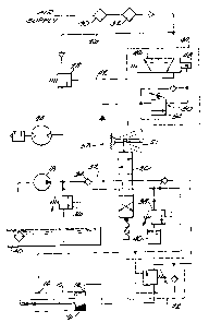
Figure 1 is a schematic illustration of an air powered hydraulic lifting
system
embodying the invention.
Figure 2 is a cross section of an automatic shutoff control valve shown in
Figure 1.
Figure 3 is a cross section view taken along line 3-3 in Figure 2.
Figure 4 is a cross section view taken along line 4-4 in Figure 2.
Figure 5 is a view taken along line 5-5 in Figure 2.
Figure 6 is a schematic view similar to Fig. 1 but showing an alternative
embodiment of the invention.
DESCRIPTION OF THE PREFERRED EMBODIMENT
Illustrated in Figure 1 is a lift cylinder 10 which in one preferred form of
the
invention can be a hydraulic cylinder. In the illustrated arrangement, the
lift cylinder 10
has ports 12 and 14 and an extensible piston 16. A fluid pump 18 is connected
to the ports
12 and 14 of the cylinder 10 through a control valve 20. The control valve 20
can be a
three position, four-way valve operated by a manually operated control lever
21. In a
preferred form of the invention a load holding valve 22 is provided in fluid
connection
between the ports 12 and 14 and the control valve 20. The load holding valve
22 provides
controlled or balanced discharge of fluid from the cylinder 10 when the
cylinder is loaded.
The load holding valve 22 is conventional in its constriction and the specific
arrangement
of components making up the load holding valve 22 is not part of the present
invention.
An air motor 24 is operably connected to the hydraulic pump 18 to selectively
drive the hydraulic pump 18 when the air motor 24 is operated. The air motor
24 is also
operably connected to a suitable source of air pressure, such as air line 26,
through an in-
line normally closed pilot operated air valve 28.
In the illustrated arrangement, the air supply line also includes a filter
separator 30
and a lubricator 32. The hydraulic circuit also includes a check valve 34
between the
pump 18 and the four-way hydraulic valve 20. The hydraulic circuit also
includes a main
pressure relief valve 36 and a retract pressure relief valve 38 to discharge
hydraulic fluid to
the tank 40 in the event the hydraulic pressure at the relief valves 36 or 38
exceeds a
selected pressure.
An automatic shutoff control valve 44 is also provided to control the supply
of
pilot air pressure to the in-line normally closed valve 28 through air line
42. The
automatic shutoff control valve includes a pilot operated 2 position, 3-way
valve 46

CA 02342069 2001-03-21
-3-
between the air supply line 26 and the pilot line 42 of the in-line normally
closed air valve
28. The pilot operated valve 46 is spring biased to a normally open position
to supply an
air signal to the pilot of air valve 28. The pilot 48 of the valve 46 is
hydraulic and is
operably connected through valve assembly 50 to the hydraulic fluid line 52
between the
pump 18 and the hydraulic control valve 20.
The construction of the valve assembly SO is shown in greater detail in Figs.
2-5.
The valve assembly SO includes a valve body 54 including a port 56 operably
connected to
the hydraulic fluid line 52. The valve body 54 includes a fluid passage 58
housing a
spring biased check valve 60, the check valve 60 including a valve seat 62 and
movable
valve member 64 biased against the valve seat 62 by a compression spring 66.
The valve
body 54 also includes a second fluid passage 68 housing a spring biased check
valve 70.
The check valve 70 includes a valve seat 71 and a movable valve member 73
biased
against the valve seat 71 by a compression spring 75. A first port 72 (Fig. 4)
supplies fluid
under pressure to the fluid passage 68 past valve seat 94~ through fluid
passage 95 to a
second port 74 that is connected to the pilot 48 of the valve 46. A movable
plunger 80 is
housed in the fluid passage and is selectively engagable with the movable
valve member
73 of check valve 70 to open the check valve 70 to provide fluid flow from
port 74 to port
93. A seal 81 surrounds plunger 80 to provide a fluid tight seal between the
plunger 80
and the bore or passage 68. The plunger 80 has its travel toward check valve
70 limited by
contact with valve seat 94. When plunger 80 contacts valve seat 94,
pressurized fluid is
prevented from passing through passage 95 to port 74. The passage 58 is
connected to the
fluid passage 68 by a passage 82 such that fluid pressure through the check
valve 60 will
act on the plunger 80 to force the plunger 80 into engagement with the check
valve 70.
The plunger 80 opens check valve 70 to provide for fluid flow from the pilot
48 to the
exhaust port 93 (Fig. 4) allowing pilot pressure from fluid passage 42 to
escape to
atmosphere.
The valve body 54 further includes a fluid passage 84 housing a bypass valve
86
for providing for hydraulic fluid flow from the passage 82 of the check valve
back to the
port 56. The bypass valve includes a valve seat 88, a movable valve member 90
and a
compression spring 92 resiliently maintaining valve member 90 against valve
seat 88.
In operation of the automatic shut-off control valve 44, when the operator has
actuated the hydraulic control valve 20 to supply fluid to the cylinder 10,
when the piston
16 reaches the end of its stroke, the hydraulic fluid pressure produced by the
pump 18 will
be supplied through the fluid line 53 as a pilot signal to the valve 46 to
shift the valve 46

CA 02342069 2001-03-21
-4-
thereby interrupting and exhausting the pilot signal to valve 28. Valve 28
will close to
interrupt the air supply to air motor 24. Air motor 24 and pump 18 will stop
until the
operator shifts the control valve 20 to either of its other operating
positions. When the
valve spool of valve 20 is moved to a second position, the hydraulic fluid
pressure in the
line 53 and at the pilot 48 will be reduced. The spring biased control valve
46 will open to
supply pilot air pressure to the in-line valve 28 causing the in-line valve to
open and
thereby cause actuation of the air motor 24 and pump 18.
One of the advantages of the construction of the invention is that it
functions to
throttle back the air motor when the fluid pressure at the air motor falls
below a
predetermined pressure. This prevents the pressure in the fluid supply line 26
from falling
below the predetermined pressure thereby preventing the loss of fluid supply
pressure
from the system.
Fig. 6 illustrates an alternative embodiment of the air powered hydraulic lift
system
of the invention. The elements which are the same as those shown in Fig. 1
have like
reference numbers. The normally closed pilot operated air valve 28 is operably
connected
by air line 42 to a manually operated valve 60. The manually operated valve 60
comprises
a normally closed valve between the air supply line 26 and the pilot of valve
28. The
manually operated valve 60 includes a plunger 62 for actuation by the operator
and to open
the air line 42. The manually operated valve 60 can be located remotely with
respect to
the hydraulic lift cylinder 10. To operate the lift cylinder 10, the operator
can first position
the control lever 21 of the hydraulic valve 20 to effect the desired movement
of the lift
cylinder 10, and the operator will then depress the plunger 62 of the manually
operated air
valve 60 to provide air flow to the air motor 24 to thereby drive the
hydraulic pump 18. If
the operator releases the plunger 62 of the manually operated air valve 60,
the air motor 24
will stop and thereby interrupt operation of the pump 18.

Representative Drawing
A single figure which represents the drawing illustrating the invention.
Administrative Status

2024-08-01:As part of the Next Generation Patents (NGP) transition, the Canadian Patents Database (CPD) now contains a more detailed Event History, which replicates the Event Log of our new back-office solution.

Please note that "Inactive:" events refers to events no longer in use in our new back-office solution.

For a clearer understanding of the status of the application/patent presented on this page, the site Disclaimer , as well as the definitions for Patent , Event History , Maintenance Fee  and Payment History  should be consulted.

Event History

Description Date
Application Not Reinstated by Deadline 2006-03-21
Time Limit for Reversal Expired 2006-03-21
Inactive: IPC from MCD 2006-03-12
Deemed Abandoned - Failure to Respond to Maintenance Fee Notice 2005-03-21
Inactive: Cover page published 2001-09-25
Application Published (Open to Public Inspection) 2001-09-22
Inactive: First IPC assigned 2001-06-21
Inactive: First IPC assigned 2001-06-20
Application Received - Regular National 2001-04-27
Letter Sent 2001-04-27
Inactive: Filing certificate - No RFE (English) 2001-04-27

Abandonment History

Abandonment Date Reason Reinstatement Date
2005-03-21

Maintenance Fee

The last payment was received on 2004-03-22

Note : If the full payment has not been received on or before the date indicated, a further fee may be required which may be one of the following

  • the reinstatement fee;
  • the late payment fee; or
  • additional fee to reverse deemed expiry.

Patent fees are adjusted on the 1st of January every year. The amounts above are the current amounts if received by December 31 of the current year.
Please refer to the CIPO Patent Fees web page to see all current fee amounts.

Fee History

Fee Type Anniversary Year Due Date Paid Date
Application fee - standard 2001-03-21
Registration of a document 2001-03-21
MF (application, 2nd anniv.) - standard 02 2003-03-21 2003-03-03
MF (application, 3rd anniv.) - standard 03 2004-03-22 2004-03-22
Owners on Record

Note: Records showing the ownership history in alphabetical order.

Current Owners on Record
TEMPLETON, KENLY & CO., INC.
Past Owners on Record
ARNOLD F. DECKER
Past Owners that do not appear in the "Owners on Record" listing will appear in other documentation within the application.
Documents

To view selected files, please enter reCAPTCHA code :


To view images, click a link in the Document Description column. To download the documents, select one or more checkboxes in the first column and then click the "Download Selected in PDF format (Zip Archive)" or the "Download Selected as Single PDF" button.

List of published and non-published patent-specific documents on the CPD .

If you have any difficulty accessing content, you can call the Client Service Centre at 1-866-997-1936 or send them an e-mail at CIPO Client Service Centre.


Document
Description 
Date
(yyyy-mm-dd) 
Number of pages   Size of Image (KB) 
Representative drawing 2001-09-11 1 9
Abstract 2001-03-20 1 17
Description 2001-03-20 4 217
Claims 2001-03-20 3 88
Drawings 2001-03-20 4 128
Courtesy - Certificate of registration (related document(s)) 2001-04-26 1 113
Filing Certificate (English) 2001-04-26 1 164
Reminder of maintenance fee due 2002-11-24 1 106
Courtesy - Abandonment Letter (Maintenance Fee) 2005-05-15 1 174
Reminder - Request for Examination 2005-11-21 1 115