Sélection de la langue

Search

Sommaire du brevet 2342069 

Énoncé de désistement de responsabilité concernant l'information provenant de tiers

Une partie des informations de ce site Web a été fournie par des sources externes. Le gouvernement du Canada n'assume aucune responsabilité concernant la précision, l'actualité ou la fiabilité des informations fournies par les sources externes. Les utilisateurs qui désirent employer cette information devraient consulter directement la source des informations. Le contenu fourni par les sources externes n'est pas assujetti aux exigences sur les langues officielles, la protection des renseignements personnels et l'accessibilité.

Disponibilité de l'Abrégé et des Revendications

L'apparition de différences dans le texte et l'image des Revendications et de l'Abrégé dépend du moment auquel le document est publié. Les textes des Revendications et de l'Abrégé sont affichés :

  • lorsque la demande peut être examinée par le public;
  • lorsque le brevet est émis (délivrance).
(12) Demande de brevet: (11) CA 2342069
(54) Titre français: VERIN HYDRAULIQUE A COMMANDE PNEUMATIQUE A ARRET AUTOMATIQUE SENSIBLE A LA CHARGE
(54) Titre anglais: AIR POWERED HYDRAULIC JACK WITH LOAD SENSING AUTO SHUT-OFF AIR CONTROL
Statut: Réputée abandonnée et au-delà du délai pour le rétablissement - en attente de la réponse à l’avis de communication rejetée
Données bibliographiques
(51) Classification internationale des brevets (CIB):
  • F15B 13/042 (2006.01)
  • F04B 17/00 (2006.01)
  • F04B 49/02 (2006.01)
  • F04B 49/08 (2006.01)
  • F15B 11/028 (2006.01)
  • F15B 11/072 (2006.01)
  • F15B 15/00 (2006.01)
(72) Inventeurs :
  • DECKER, ARNOLD F. (Etats-Unis d'Amérique)
(73) Titulaires :
  • TEMPLETON, KENLY & CO., INC.
(71) Demandeurs :
  • TEMPLETON, KENLY & CO., INC. (Etats-Unis d'Amérique)
(74) Agent: MACRAE & CO.
(74) Co-agent:
(45) Délivré:
(22) Date de dépôt: 2001-03-21
(41) Mise à la disponibilité du public: 2001-09-22
Licence disponible: S.O.
Cédé au domaine public: S.O.
(25) Langue des documents déposés: Anglais

Traité de coopération en matière de brevets (PCT): Non

(30) Données de priorité de la demande:
Numéro de la demande Pays / territoire Date
09/533,416 (Etats-Unis d'Amérique) 2000-03-22

Abrégés

Abrégé anglais


The invention provides an improved fluid motor powered lift system having a
valve arrangement for reducing or interrupting the fluid flow supplied to the
motor when
the pressure in the lift system exceeds a predetermined pressure. A valve
arrangement is
provided to shut-off or throttle back the fluid supplied to the fluid motor
when the fluid
pressure in the lift reaches a predetermined level. When the pressure in the
lift system
exceeds the predetermined level, pilot pressure is supplied to an automatic
shut-off valve,
and this in turn reduces fluid flow to fluid air motor thereby reducing or
preventing pump
pressure.

Revendications

Note : Les revendications sont présentées dans la langue officielle dans laquelle elles ont été soumises.


-5-
I Claim:
1. An air powered hydraulic lift system comprising:
a hydraulic cylinder having at least one fluid port for supply of hydraulic
fluid pressure to the cylinder,
an extensible piston in the cylinder,
a hydraulic fluid pump for selectively supplying fluid under pressure to the
fluid port,
an air pressure driven motor operably connected to the hydraulic fluid
pump to drive the hydraulic fluid pump, and
a control valve for controlling the supply of hydraulic fluid pressure from
the hydraulic fluid pump to the fluid port, and
a valve assembly reducing the supply of air pressure to the air pressure
driven motor when the fluid pressure supplied to the control valve exceeds a
predetermined fluid pressure.
2. An air powered hydraulic lift system as set forth in claim 1, wherein the
valve assembly includes a normally closed pilot operated valve controlling
supply of fluid
pressure to the motor and connected to the fluid pump.
3. An air powered hydraulic lift system as set forth in claim 1, wherein the
normally closed pilot operated valve includes a pilot and wherein the valve
assembly
includes a shutoff control valve.
4. An air powered hydraulic lift system as set forth in claim 1, wherein the
normally closed pilot operated valve is operably connected to the fluid pump
such that
when the hydraulic fluid pressure generated by the fluid pump exceeds a
predetermined
pressure, the normally closed pilot operated valve closes to reduce flow to
the air motor.
5. An air powered hydraulic lift system as set forth in claim 1, and further
including an air motor actuating valve between the air supply and the pilot of
the normally
closed pilot operated valve, the air motor actuating valve including a pilot
actuated by
hydraulic fluid pressure supplied by the fluid pump.

-6-
6. A fluid powered fluid lift system comprising:
a cylinder having at least one fluid port for supply of fluid pressure to the
cylinder,
an extensible piston in the cylinder,
a fluid pump for selectively supplying fluid under pressure to the fluid port,
a fluid pressure driven motor operably connected to the fluid pump to drive
the fluid pump,
a control valve for controlling the supply of fluid pressure from the fluid
pump to the fluid port, and
a valve assembly controlling the supply of fluid pressure to the motor and
reducing the supply of fluid pressure to the motor when the fluid pressure
supplied to the
control valve exceeds a predetermined fluid pressure.
7. A fluid powered lift system as set forth in claim 6, the valve assembly
including a normally closed pilot operated valve controlling supply of fluid
pressure to the
motor and connected to the fluid pump.
8. A fluid powered lift system as set forth in claim 7, the normally closed
pilot
operated valve including a pilot and wherein the valve assembly includes a
shutoff control
valve.

9. An air powered hydraulic lift system comprising:
a hydraulic cylinder having at least one fluid port for supply of hydraulic
fluid pressure to the cylinder,
an extensible piston in the cylinder,
a hydraulic fluid pump for selectively supplying fluid under pressure to the
fluid port,
an air pressure driven motor operably connected to the hydraulic fluid
pump to drive the hydraulic fluid pump, and
a valve assembly for controlling the supply of air pressure to the air
pressure driven motor, the valve assembly including a normally closed valve
shiftable to
an open position in response to manual actuation by an operator, the valve
providing air
flow to the air motor when the valve is shifted to an open position and
interrupting air flow
to the motor when the valve is closed.
10. An air powered hydraulic lift system as set forth in claim 1, wherein the
valve assembly is spaced apart from the hydraulic cylinder to provide a remote
control for
operation of the air motor.

Description

Note : Les descriptions sont présentées dans la langue officielle dans laquelle elles ont été soumises.

CA 02342069 2001-03-21
AIR POWERED HYDRAULIC JACK
WITH LOAD SENSING AUTO SHUT-OFF AIR CONTROL
FIELD OF THE INVENTION
The invention relates to air powered hydraulic lifting systems and more
particularly
to controls for effecting actuation of such systems.
BACKGROUND PRIOR ART
In hydraulic lift systems it is advantageous in some applications to use an
air
pressure driven motor to drive a hydraulic fluid pump which selectively
supplies hydraulic
fluid pressure to the hydraulic cylinder of the hydraulic lift system. An
example of a prior
art arrangement is illustrated in U.S. Patent No. 4,251,055. Attention is also
directed to
U.S. Patent No. 4,889,472.
In prior art arrangements of such hydraulic lift systems a manually operated
control
valve is provided to control the flow of hydraulic fluid from the pump to the
cylinder. A
pressure relief valve is connected between the pump and the fluid cylinder to
exhaust fluid
to the tank when fluid pressure reaches a predetermined pressure. If the
cylinder reaches
the end of its stroke and the hydraulic pump continues to operate, hydraulic
fluid is
exhausted to the tank through the pressure relief valve to the tank. This can
result in
damaging heat generation in the hydraulic system and destruction or
deterioration of
components of the system such as seals and other non-metallic components.
SUMMARY OF THE INVENTION
The invention provides an improved fluid motor powered fluid lift system
having a
valve arrangement for reducing or interrupting the fluid supplied to the fluid
motor when
the pressure in the lift system exceeds a predetermined pressure.
One of the features of the construction of the invention is that a valve
arrangement
is provided to shut-off or throttle back the fluid supplied to the fluid motor
when the fluid
pressure reaches a predetermined level. When the pressure of the lift system
exceeds the
predetermined level, pilot pressure is supplied to an automatic shut-off
valve, and this in
turn shuts off fluid flow to the fluid motor thereby preventing the pump from
continuing to
supply pressure that would otherwise be bypassed by relief valves to exhaust
back to the
reservoir.

CA 02342069 2001-03-21
-2-
BRIEF DESCRIPTION OF THE DRAWINGS
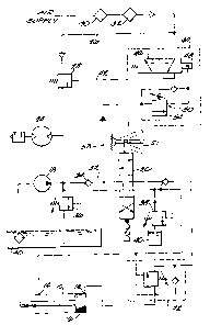
Figure 1 is a schematic illustration of an air powered hydraulic lifting
system
embodying the invention.
Figure 2 is a cross section of an automatic shutoff control valve shown in
Figure 1.
Figure 3 is a cross section view taken along line 3-3 in Figure 2.
Figure 4 is a cross section view taken along line 4-4 in Figure 2.
Figure 5 is a view taken along line 5-5 in Figure 2.
Figure 6 is a schematic view similar to Fig. 1 but showing an alternative
embodiment of the invention.
DESCRIPTION OF THE PREFERRED EMBODIMENT
Illustrated in Figure 1 is a lift cylinder 10 which in one preferred form of
the
invention can be a hydraulic cylinder. In the illustrated arrangement, the
lift cylinder 10
has ports 12 and 14 and an extensible piston 16. A fluid pump 18 is connected
to the ports
12 and 14 of the cylinder 10 through a control valve 20. The control valve 20
can be a
three position, four-way valve operated by a manually operated control lever
21. In a
preferred form of the invention a load holding valve 22 is provided in fluid
connection
between the ports 12 and 14 and the control valve 20. The load holding valve
22 provides
controlled or balanced discharge of fluid from the cylinder 10 when the
cylinder is loaded.
The load holding valve 22 is conventional in its constriction and the specific
arrangement
of components making up the load holding valve 22 is not part of the present
invention.
An air motor 24 is operably connected to the hydraulic pump 18 to selectively
drive the hydraulic pump 18 when the air motor 24 is operated. The air motor
24 is also
operably connected to a suitable source of air pressure, such as air line 26,
through an in-
line normally closed pilot operated air valve 28.
In the illustrated arrangement, the air supply line also includes a filter
separator 30
and a lubricator 32. The hydraulic circuit also includes a check valve 34
between the
pump 18 and the four-way hydraulic valve 20. The hydraulic circuit also
includes a main
pressure relief valve 36 and a retract pressure relief valve 38 to discharge
hydraulic fluid to
the tank 40 in the event the hydraulic pressure at the relief valves 36 or 38
exceeds a
selected pressure.
An automatic shutoff control valve 44 is also provided to control the supply
of
pilot air pressure to the in-line normally closed valve 28 through air line
42. The
automatic shutoff control valve includes a pilot operated 2 position, 3-way
valve 46

CA 02342069 2001-03-21
-3-
between the air supply line 26 and the pilot line 42 of the in-line normally
closed air valve
28. The pilot operated valve 46 is spring biased to a normally open position
to supply an
air signal to the pilot of air valve 28. The pilot 48 of the valve 46 is
hydraulic and is
operably connected through valve assembly 50 to the hydraulic fluid line 52
between the
pump 18 and the hydraulic control valve 20.
The construction of the valve assembly SO is shown in greater detail in Figs.
2-5.
The valve assembly SO includes a valve body 54 including a port 56 operably
connected to
the hydraulic fluid line 52. The valve body 54 includes a fluid passage 58
housing a
spring biased check valve 60, the check valve 60 including a valve seat 62 and
movable
valve member 64 biased against the valve seat 62 by a compression spring 66.
The valve
body 54 also includes a second fluid passage 68 housing a spring biased check
valve 70.
The check valve 70 includes a valve seat 71 and a movable valve member 73
biased
against the valve seat 71 by a compression spring 75. A first port 72 (Fig. 4)
supplies fluid
under pressure to the fluid passage 68 past valve seat 94~ through fluid
passage 95 to a
second port 74 that is connected to the pilot 48 of the valve 46. A movable
plunger 80 is
housed in the fluid passage and is selectively engagable with the movable
valve member
73 of check valve 70 to open the check valve 70 to provide fluid flow from
port 74 to port
93. A seal 81 surrounds plunger 80 to provide a fluid tight seal between the
plunger 80
and the bore or passage 68. The plunger 80 has its travel toward check valve
70 limited by
contact with valve seat 94. When plunger 80 contacts valve seat 94,
pressurized fluid is
prevented from passing through passage 95 to port 74. The passage 58 is
connected to the
fluid passage 68 by a passage 82 such that fluid pressure through the check
valve 60 will
act on the plunger 80 to force the plunger 80 into engagement with the check
valve 70.
The plunger 80 opens check valve 70 to provide for fluid flow from the pilot
48 to the
exhaust port 93 (Fig. 4) allowing pilot pressure from fluid passage 42 to
escape to
atmosphere.
The valve body 54 further includes a fluid passage 84 housing a bypass valve
86
for providing for hydraulic fluid flow from the passage 82 of the check valve
back to the
port 56. The bypass valve includes a valve seat 88, a movable valve member 90
and a
compression spring 92 resiliently maintaining valve member 90 against valve
seat 88.
In operation of the automatic shut-off control valve 44, when the operator has
actuated the hydraulic control valve 20 to supply fluid to the cylinder 10,
when the piston
16 reaches the end of its stroke, the hydraulic fluid pressure produced by the
pump 18 will
be supplied through the fluid line 53 as a pilot signal to the valve 46 to
shift the valve 46

CA 02342069 2001-03-21
-4-
thereby interrupting and exhausting the pilot signal to valve 28. Valve 28
will close to
interrupt the air supply to air motor 24. Air motor 24 and pump 18 will stop
until the
operator shifts the control valve 20 to either of its other operating
positions. When the
valve spool of valve 20 is moved to a second position, the hydraulic fluid
pressure in the
line 53 and at the pilot 48 will be reduced. The spring biased control valve
46 will open to
supply pilot air pressure to the in-line valve 28 causing the in-line valve to
open and
thereby cause actuation of the air motor 24 and pump 18.
One of the advantages of the construction of the invention is that it
functions to
throttle back the air motor when the fluid pressure at the air motor falls
below a
predetermined pressure. This prevents the pressure in the fluid supply line 26
from falling
below the predetermined pressure thereby preventing the loss of fluid supply
pressure
from the system.
Fig. 6 illustrates an alternative embodiment of the air powered hydraulic lift
system
of the invention. The elements which are the same as those shown in Fig. 1
have like
reference numbers. The normally closed pilot operated air valve 28 is operably
connected
by air line 42 to a manually operated valve 60. The manually operated valve 60
comprises
a normally closed valve between the air supply line 26 and the pilot of valve
28. The
manually operated valve 60 includes a plunger 62 for actuation by the operator
and to open
the air line 42. The manually operated valve 60 can be located remotely with
respect to
the hydraulic lift cylinder 10. To operate the lift cylinder 10, the operator
can first position
the control lever 21 of the hydraulic valve 20 to effect the desired movement
of the lift
cylinder 10, and the operator will then depress the plunger 62 of the manually
operated air
valve 60 to provide air flow to the air motor 24 to thereby drive the
hydraulic pump 18. If
the operator releases the plunger 62 of the manually operated air valve 60,
the air motor 24
will stop and thereby interrupt operation of the pump 18.

Dessin représentatif
Une figure unique qui représente un dessin illustrant l'invention.
États administratifs

2024-08-01 : Dans le cadre de la transition vers les Brevets de nouvelle génération (BNG), la base de données sur les brevets canadiens (BDBC) contient désormais un Historique d'événement plus détaillé, qui reproduit le Journal des événements de notre nouvelle solution interne.

Veuillez noter que les événements débutant par « Inactive : » se réfèrent à des événements qui ne sont plus utilisés dans notre nouvelle solution interne.

Pour une meilleure compréhension de l'état de la demande ou brevet qui figure sur cette page, la rubrique Mise en garde , et les descriptions de Brevet , Historique d'événement , Taxes périodiques et Historique des paiements devraient être consultées.

Historique d'événement

Description Date
Demande non rétablie avant l'échéance 2006-03-21
Le délai pour l'annulation est expiré 2006-03-21
Inactive : CIB de MCD 2006-03-12
Réputée abandonnée - omission de répondre à un avis sur les taxes pour le maintien en état 2005-03-21
Inactive : Page couverture publiée 2001-09-25
Demande publiée (accessible au public) 2001-09-22
Inactive : CIB en 1re position 2001-06-21
Inactive : CIB en 1re position 2001-06-20
Demande reçue - nationale ordinaire 2001-04-27
Lettre envoyée 2001-04-27
Inactive : Certificat de dépôt - Sans RE (Anglais) 2001-04-27

Historique d'abandonnement

Date d'abandonnement Raison Date de rétablissement
2005-03-21

Taxes périodiques

Le dernier paiement a été reçu le 2004-03-22

Avis : Si le paiement en totalité n'a pas été reçu au plus tard à la date indiquée, une taxe supplémentaire peut être imposée, soit une des taxes suivantes :

  • taxe de rétablissement ;
  • taxe pour paiement en souffrance ; ou
  • taxe additionnelle pour le renversement d'une péremption réputée.

Les taxes sur les brevets sont ajustées au 1er janvier de chaque année. Les montants ci-dessus sont les montants actuels s'ils sont reçus au plus tard le 31 décembre de l'année en cours.
Veuillez vous référer à la page web des taxes sur les brevets de l'OPIC pour voir tous les montants actuels des taxes.

Historique des taxes

Type de taxes Anniversaire Échéance Date payée
Taxe pour le dépôt - générale 2001-03-21
Enregistrement d'un document 2001-03-21
TM (demande, 2e anniv.) - générale 02 2003-03-21 2003-03-03
TM (demande, 3e anniv.) - générale 03 2004-03-22 2004-03-22
Titulaires au dossier

Les titulaires actuels et antérieures au dossier sont affichés en ordre alphabétique.

Titulaires actuels au dossier
TEMPLETON, KENLY & CO., INC.
Titulaires antérieures au dossier
ARNOLD F. DECKER
Les propriétaires antérieurs qui ne figurent pas dans la liste des « Propriétaires au dossier » apparaîtront dans d'autres documents au dossier.
Documents

Pour visionner les fichiers sélectionnés, entrer le code reCAPTCHA :


Pour visualiser une image, cliquer sur un lien dans la colonne description du document. Pour télécharger l'image (les images), cliquer l'une ou plusieurs cases à cocher dans la première colonne et ensuite cliquer sur le bouton "Télécharger sélection en format PDF (archive Zip)" ou le bouton "Télécharger sélection (en un fichier PDF fusionné)".

Liste des documents de brevet publiés et non publiés sur la BDBC .

Si vous avez des difficultés à accéder au contenu, veuillez communiquer avec le Centre de services à la clientèle au 1-866-997-1936, ou envoyer un courriel au Centre de service à la clientèle de l'OPIC.


Description du
Document 
Date
(aaaa-mm-jj) 
Nombre de pages   Taille de l'image (Ko) 
Dessin représentatif 2001-09-11 1 9
Abrégé 2001-03-20 1 17
Description 2001-03-20 4 217
Revendications 2001-03-20 3 88
Dessins 2001-03-20 4 128
Courtoisie - Certificat d'enregistrement (document(s) connexe(s)) 2001-04-26 1 113
Certificat de dépôt (anglais) 2001-04-26 1 164
Rappel de taxe de maintien due 2002-11-24 1 106
Courtoisie - Lettre d'abandon (taxe de maintien en état) 2005-05-15 1 174
Rappel - requête d'examen 2005-11-21 1 115