Note: Descriptions are shown in the official language in which they were submitted.
CA 02342598 2001-04-03
SPECIFICATION
TITLE OF THE INVENTION
SHIFT CONTROL DEVICE FOR AUTOMATIC TRANSMISSION
FIELD OF THE INVENTION
The present invention relates to a control device for an
automatic transmission, with which a shift control valve equipped with a
manual valve and the like and operating according to the movement of a
shift lever by the driver performs switching between a reverse range,
neutral range, and drive range, and performs automatic shift control in the
reverse and drive ranges.
BACKGROUND OF THE INVENTION
With a vehicle equipped with an automatic transmission such as
this, the driver moves a shift lever, which actuates a manual valve, which
selects the shift range (or shift position), and shift control is
automatically
carried out within this selected shift range on the basis of the amount of
accelerator pedal depression, vehicle speed, and so forth. The shift ranges
that can be selected by movement of the shift lever are the park range (P
range), reverse range (R range), neutral range (N range), and drive range
(such as the D range), with the drive range frequently consisting of a
number of ranges, such as the D range, S range, 2 range, and 1 range.
An automatic transmission is designed such that automatic shift
control is performed by providing a plurality of solenoid valves, shift
valves,
1
CA 02342598 2001-04-03
and so forth to friction engagement elements (such as clutches) for setting
the various gear speeds from the manual valve, and controlling the
operation of the shift valves with the solenoid valves, in order to perform
shift control automatically on the basis of the amount of accelerator pedal
depression, vehicle speed, and so forth within each shift range set by the
operation of the manual valve as above. Shift control device structures such
as this are disclosed, for example, in Japanese Laid-Open Patent
Applications H6-264996 and H9-269062.
With an automatic transmission control device such as this, an
oil line going through a solenoid valve, a shift valve, and so forth is
switched
for every range set by the manual valve, so numerous solenoid valves, shift
valves, and the like are needed, which is a problem in that a greater number
of parts in the control device tends to lead to higher cost.
In particular, the manual valve switches between the drive and
reverse ranges by switching the hydraulic supply oil line going to the drive
friction engagement element and the hydraulic supply oil line going to the
reverse friction engagement element. Accordingly, the solenoid valve, shift
valve, and so forth provided to the hydraulic supply oil line linked to the
drive friction engagement element need to be provided separately from the
solenoid valve, shift valve, and so forth provided to the hydraulic supply oil
line linked to the reverse friction engagement element, which tends to drive
up the cost of the control device, and also requires independent control for
drive and reverse, making the control more difficult.
SUMIVIARY OF THE INVENTION
2
CA 02342598 2001-04-03
It is an object of the present invention to provide a shift control
device for an automatic transmission, structured such that the solenoid
valve, shift valves, and so forth used for shift control in the drive and
reverse
shift ranges can be partially shared, allowing the structure of the control
device to be simpler, and affording optimal shift control in each range.
To achieve the stated object, the shift control device for an
automatic transmission pertaining to the present invention has a power
transmission mechanism (such as a parallel shaft transmission TM in the
embodiments) comprising a drive power transmission path for transmitting
drive force, and a reverse power transmission path for transmitting reverse
power; a drive friction engagement element (such as a LOW clutch 11 in the
embodiments) for selecting the drive power transmission path and a reverse
friction engagement element (such as a 4'h clutch 14 in the embodiments) for
selecting the reverse power transmission path; and a hydraulic control valve
(such as a shift control valve CV in the embodiments) for controlling the
supply of engagement control hydraulic pressure to the drive friction
engagement element and the reverse friction engagement element. This
hydraulic control valve has a main pressure supply source (such as a main
regulator valve 50, oil line 100, etc., in the embodiments) for supplying the
main pressure of the engagement control 1-iydraulic pressure a manual valve
(such as a manual valve 58 in the embodiments) that is switched according
to shift lever operation, first and second main pressure oil lines (such as
oil
lines 151, 152, 155, etc., in the embodiments) disposed in parallel between
the main pressure supply source and the manual valve, and a plurality of
engagement element oil lines (such as oil lines 121, 122, 156, 130, 131, 132,
133, etc., in the embodiments) disposed between the manual valve and the
drive and reverse friction engagement elements. Also, a linear solenoid
3
CA 02342598 2001-04-03
valve (such as a first linear solenoid valve 86, that is, linear A, in the
embodiments) that allows the main pressure to be set as desired is provided
to at least one of the first and second main pressure oil lines.
With a shift control device for an automatic transmission
structured such as this, the engagement control hydraulic pressure from the
first and second main pressure oil lines can be selectively supplied to the
drive friction engagement element or the reverse friction engagement
element on the basis of the operation of the manual valve. Specifically, the
first and second main pressure oil lines can be used for both drive and
reverse control, so fewer parts are needed for the shift control device, and
control is simpler.
Accordingly, it is preferable if the above-mentioned first and
second main pressure oil lines are linked to the drive friction engagement
element when the manual valve is in the drive position, and are linked to
the reverse friction engagement element when the manual valve is in the
reverse position.
With the present invention, if the first and second main pressure
oil lines are used selectively, it is possible, for example, to control the
start of
engagement by precisely controlling the engagement hydraulic pressure
using a main pressure oil line having a linear solenoid valve, and upon
completion of the engagement start control, to supply the line pressure
directly using another main pressure oil line, so that the friction
engagement element is securely engaged. As a result, the linear solenoid
valve is controlled at a lower pressure, and the structure thereof can be
simpler. Furthermore, even if there is a malfunction of the linear solenoid
valve, the friction engagement element can still be engaged by using the
other main pressure oil line, so reliability is better.
4
CA 02342598 2001-04-03
It is also preferable if a mechanical clutch mechanism (such as a
dog-tooth clutch 16 in the embodiments) for mechanically switching the
drive power transmission path and the reverse power transmission path,
and a drive/reverse selection hydraulic servo mechanism (such as a
drive/reverse selection hydraulic servo mechanism 70 in the embodiments)
that hydraulically controls the operation of this mechanical clutch
mechanism, are provided, and if the drive/reverse selection hydraulic servo
mechanism is disposed within the hydraulic control valve, and the reverse
engagement element oil line that connects the reverse friction engagement
element to the manual valve is formed through the drive/ reverse selection
hydraulic servo mechanism operating on the reverse side. This keeps the
reverse friction engagement element from being engaged unless the
drive/reverse selection hydraulic servo mechanism is switched to the reverse
side, which improves reliability.
Further scope of applicability of the present invention will
become apparent from the detailed description given hereinafter. However,
it should be understood that the detailed description and specific examples,
while indicating preferred embodiments of the invention, are given by way
of illustration only, since various changes and modifications within the
spirit
and scope of the invention will become apparent to those skilled in the art
from this detailed description.
BRIEF DESCRIPTION OF THE DRAWINGS
The present invention will become more fully understood from
the detailed description given herein below and the accompanying drawings
which are given by way of illustration only, and thus are not limitative of
the present invention and wherein:
s
CA 02342598 2001-04-03
Fig. 1 is a schematic block diagram of the overall structure of the
control device pertaining to the present invention, and an automatic
transmission controlled by this device;
Fig. 2 is a cross section of a five-speed automatic transmission
that is shift controlled by the control device pertaining to the present
invention;
Fig. 3 is a partial cross section of the above-mentioned five-speed
automatic transmission;
Fig. 4 consists of skeleton diagrams illustrating the power
transmission system of the above-mentioned five-speed automatic
transmission;
Fig. 5 is a schematic diagram illustrating the shaft positional
relationship of the above-mentioned five-speed automatic transmission;
Fig. 6 is a hydraulic circuit diagram illustrating the structure of
the shift control device in the above-mentioned five-speed automatic
transmission;
Figs. 7 to 12 are hydraulic circuit diagrams illustrating enlarged
detail views of the hydraulic circuit in Fig. 6;
Fig. 13 is a schematic illustrating the oil lines linking the LOW
clutch and the reverse clutch from the hydraulic pressure source in the
above-mentioned hydraulic circuit;
Fig. 14 consists of skeleton diagrams illustrating the power
transmission system of a four-speed automatic transmission pertaining to
the present invention;
~
CA 02342598 2001-04-03
Fig. 15 is a hydraulic circuit diagram illustrating the structure
of the shift control device in the above-mentioned four-speed automatic
transmission;
Figs. 16 to 21 are hydraulic circuit diagrams illustrating
enlarged detail views of the hydraulic circuit in Fig. 15; and
Fig. 22 is a schematic illustrating the oil lines linking the LOW
clutch and the reverse clutch from the hydraulic pressure source in the
above-mentioned hydraulic circuit.
DESCRIPTION OF THE PREFERRED EMBODIMENTS
A shift control device pertaining to a preferred embodiment of
the present invention, and an automatic transmission in which the range
switching is controlled by this device, will now be described through
reference to the drawings. Fig. 1 shows the overall structure of the
automatic transmission pertaining to the present invention, in which the
power transmission mechanism is constituted by an automatic transmission
TM that transmits the output of an engine ENG at different speeds to the
wheels. The shift control of this automatic transmission TM is performed
hydraulically by a shift control valve CV, and the operation of the shift
control valve CV is accomplished by actuating a solenoid valve with a shift
control signal from an electronic control unit ECU. The electronic control
unit ECU is linked to a shifter device 5 via a signal line 7, and receives
signals from the shifter device 5 indicating the shift position of a shift
lever
5a. The shift lever 5a is linked to a manual valve inside the shift control
valve CV via a cable 6, and a spool of the manual valve is moved according
to the movement of the shift lever 5a.
7
CA 02342598 2001-04-03
First, let us describe the structure of the automatic transmission
TM through reference to Figs. 2 to 5. This transmission comprises a
transmission housing HSG, inside of which are disposed a torque converter
TC linked to an engine output shaft (not shown), a parallel shaft
transmission mechanism TM linked to an output member (turbine) of the
torque converter TC, and a differential mechanism DF having a final
reduction driven gear 6b that meshes with a final reduction drive gear 6a of
this transmission mechanism TM. Drive force is transmitted from the
differential mechanism DF to the left and right wheels.
The parallel shaft transmission mechanism TM has a first input
shaft 1, a second input shaft 2, a countershaft 3, and an idle shaft 4
extending parallel to each other, and the center-line positions of these
shafts
are indicated by S1, S2, S3, and S5, respectively, in Fig. 5. The power
transmission structure of this parallel shaft transmission mechanism TM is
shown in Figs. 4A and 4B. Fig. 4A is a cross section through the first input
shaft 1(S 1), the countershaft 3 (S3), and the second input shaft 2 (S2) along
the IVA-IVA line in Fig. 5, while Fig. 4B is a cross section through the first
input shaft 1 (S 1), the idle shaft 4 (S4), and the second input shaft 2(S2)
along the IVB-IVB line in Fig. 5. Fig. 2 is a cross section of the
transmission
mechanism TM corresponding to Fig. 4A, and Fig. 3 is that corresponding to
Fig. 4B.
The first input shaft 1 is coupled to the turbine of the torque
converter TC, is rotatably supported by bearings 41a and 41b, receives the
drive force from the turbine, and rotates along with the turbine. The first
input shaft 1 is provided with a fifth-speed drive gear 25a, a 5r'' clutch 15,
a
4th clutch 14, a fourth-speed drive gear 24a, a reverse drive gear 26a, and a
first connecting gear 31, in that order starting from the torque converter TC
8
CA 02342598 2001-04-03
side (the right side in the drawing). The fifth-speed drive gear 25a is
rotatably provided on the first input shaft 1, and is engaged with and
disengaged from the first input shaft 1 by the hydraulically operated 5t''
clutch 15. The fourth-speed drive gear 24a and the reverse drive gear 26a
are integrally linked and rotatably provided on the first input shaft 1, and
are engaged with and disengaged from the first input shaft 1 by the
hydraulically operated 4'" clutch 14. The first connecting gear 31 is linked
with the first input shaft 1 in a cantilevered state, located to the outside
of
the bearing 41a rotatably supporting the first input shaft 1.
The second input shaft 2 is rotatably supported by bearings 42a
and 42b, and is provided with a 2 `' clutch 12, a second-speed drive gear 22a,
a LOW drive gear 21a, a LOW clutch 11, a 3r`' clutch 13, a third-speed drive
gear 23a, and a fourth connecting gear 34, in that order starting from the
right side in the drawing. The second-speed drive gear 22a, the LOW drive
gear 21a, and the third-speed drive gear 23a are rotatably provided on the
second input shaft 2, and are engaged with and disengaged from the second
input shaft 2 by the hydraulically operated 2 `' clutch 12, LOW clutch 11,
and 3rd clutch 13. The fourth connecting gear 34 is linked to the second
input shaft 2.
The idle shaft 4 is rotatably supported by bearings 45a and 45b,
and is provided with a second connecting gear 32 and a third connecting
gear 33 that are integral with this shaft. The second connecting gear 32
meshes with the first connecting gear 31, and the third connecting gear 33
meshes with the fourth connecting gear 34. These first to fourth connecting
gears constitute a connecting gear train 30, and the rotation of the first
input shaft 1 is constantly transmitted to the second input shaft 2 via the
connecting gear train 30.
9
CA 02342598 2001-04-03
The countershaft 3 is rotatably supported by bearings 43a and
43b, and the final reduction drive gear 6a, a second-speed driven gear 22b, a
LOW driven gear 21b, a fifth-speed driven gear 25b, a third-speed driven
gear 23b, a fourth-speed driven gear 24b, a dog-tooth clutch 16, and a
reverse driven gear 26c are provided on this shaft, in that order starting
from the right side in the drawing. The final reduction drive gear 6a, the
second-speed driven gear 22b, the LOW driven gear 21b, the fifth-speed
driven gear 25b and the third-speed driven gear 23b are linked to and rotate
integrally with the countershaft 3. The fourth-speed driven gear 24b is
rotatably provided on the countershaft 3. The reverse driven gear 26c is also
rotatably provided on the countershaft 3. The dog-tooth clutch 16 operates
in the axial direction, and can engage and disengage the fourth-speed driven
gear 24b and the countershaft 3, or engage and disengage the reverse driven
gear 26c and the countershaft 3.
As shown in the drawings, the LOW drive gear 2 la meshes with
the LOW driven gear 21b, the second-speed drive gear 22a meshes with the
second-speed driven gear 22b, the third-speed drive gear 23a meshes with
the third-speed driven gear 23b, the fourth-speed drive gear 24a meshes
with the fourth-speed driven gear 24b, and the fifth-speed drive gear 25a
meshes with the fifth-speed driven gear 25b. Further, the reverse drive gear
26a meshes with the reverse driven gear 26c via a reverse idler gear 26b
(see Fig. 3).
Although not depicted in the drawings, the final reduction drive
gear 6a meshes with the final reduction driven gear 6b (see Fig. 2), and the
rotation of the countershaft 3 is transmitted to the differential mechanism
DF via the final reduction drive gear 6a and final reduction driven gear 6b.
CA 02342598 2001-04-03
The setting of the various gear speeds and the power
transmission routes thereof in a transmission structured as above will now
be described. With this transmission, in the drive range, the dog-tooth
clutch 16 moves to the right in the drawing, and the fourth-speed driven
gear 24b is engaged with the countershaft 3. In the reverse range, the dog-
tooth clutch 16 moves to the left, and the reverse driven gear 26c is engaged
with the countershaft 3.
First, let us describe the gear speeds in the drive range. Low
gear is set by engagement of the LOW clutch 11. The rotational drive force
transmitted from the torque converter TC to the first input shaft 1 is
transmitted through the connecting gear train 30 to the second input shaft 2.
Since the LOW clutch 11 is engaged here, the LOW drive gear 21a is
rotationally driven along with the second input shaft 2, the LOW driven
gear 2 lb meshed therewith is rotationally driven, and the countershaft 3 is
driven. This drive force is transmitted through the final reduction gear
train 6a and 6b to the differential mechanism DF.
Second gear is set by engagement of the 2"l clutch 12. The
rotational drive force transmitted from the torque converter TC to the first
input shaft 1 is transmitted through the connecting gear train 30 to the
second input shaft 2. Since the 2 `' clutch 12 is engaged here, the second-
speed drive gear 22a is rotationally driven along with the second input shaft
2, the second-speed driven gear 22b meshed therewith is rotationally driven,
and the countershaft 3 is driven. This drive force is transmitted through the
final reduction gear train 6a and 6b to the differential mechanism DF.
Third gear is set by engagement of the 3"'l clutch 13. The
rotational drive force transmitted from the torque converter TC to the first
input shaft 1 is transmitted through the connecting gear train 30 to the
11
CA 02342598 2001-04-03
second input shaft 2. Since the 3a clutch 13 is engaged here, the third-speed
drive gear 23a is rotationally driven along with the second input shaft 2, the
third-speed driven gear 23b meshed therewith is rotationally driven, and
the countershaft 3 is driven. This drive force is transmitted through the
final reduction gear train 6a and 6b to the differential mechanism DF.
Fourth gear is set by engagement of the 4'' clutch 14. The
rotational drive force transmitted from the torque converter TC to the first
input shaft 1 rotationally drives the fourth-speed drive gear 24a through the
4'" clutch 14, and the fourth-speed driven gear 24b meshed therewith is
rotationally driven. Here, in the drive range, the fourth-speed driven gear
24b is engaged with the countershaft 3 by the dog-tooth clutch 16, so the
countershaft 3 is driven, and this drive force is transmitted through the
final
reduction gear train 6a and 6b to the differential mechanism DF.
Fifth gear is set by engagement of the 5'" clutch 15. The
rotational drive force transmitted from the torque converter TC to the first
input shaft 1 rotationally drives the fifth-speed drive gear 25a through the
5`" clutch 15, and the fourth-speed driven gear 24b meshed therewith is
rotationally driven. Since the fifth-speed driven gear 25b is engaged with
the countershaft 3, the countershaft 3 is driven, and this drive force is
transmitted through the final reduction gear train 6a and 6b to the
differential mechanism DF.
Reverse gear is set by engaging the 4t"' clutch 14 and moving the
dog-tooth clutch 16 to the left. The rotational drive force transmitted from
the torque converter TC to the first input shaft 1 rotationally drives the
reverse drive gear 26a 4'1' clutch 14, and rotationally drives the reverse
driven gear 26c meshed with this gear 26a through the reverse idler gear
26b. Since the reverse driven gear 26c is engaged with the countershaft 3 by
12
CA 02342598 2001-04-03
the dog-tooth clutch 16 in the reverse range here, the countershaft 3 is
driven, and this drive force is transmitted through the final reduction gear
train 6a and 6b to the differential mechanism DF. It can be seen from this
that the 4t'' clutch 14 doubles as a reverse clutch. '
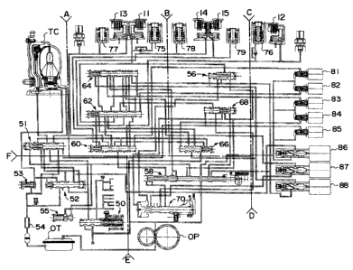
Figs. 6 to 12 illustrate the hydraulic circuits that make up the
shift control valve CV that controls shifting in an automatic transmission
structured as above. These drawings will now be described. Figs. 7 to 12
are enlarged detail views of the six portions of Fig. 6 indicated by one-dot
chain lines A to F. In these hydraulic circuit diagrams, places where an oil
line is open indicate that the line is connected to a drain.
This device has an oil pump OP that discharges hydraulic oil
from an oil tank OT. The oil pump OP is driven by the engine and supplies
hydraulic oil to an oil line 100. The oil line 100 is connected to a main
regulator valve 50 via an oil line 100a, and the pressure is adjusted at this
valve, generating a line pressure PL in the oil lines 100 and 100a. This line
pressure PL is supplied through an oil line 100b to a manual valve 58, and
is supplied through an oil line 100c to a fourth shift valve 66. The oil line
100a is always connected to an oil line 100d via the port of the manual valve
58 (always connected, regardless of how the manual valve 58 is operating),
and the line pressure PL is always supplied through the oil line 100d to first
to fifth on/off solenoid valves 81 to 85 and a first linear solenoid valve 86.
Any extra oil from the main regulator valve 50 which makes the
line pressure PL is supplied to an oil line 191, as well as to an oil line
192.
The hydraulic oil supplied to the oil line 191 is controlled by a lock-up
shift
valve 51, a lock-up control valve 52, and a torque converter check valve 53,
and is used in the lock-up control of the torque converter TC, after which it
is returned to the oil tank OT through an oil cooler 54. Since control of the
13
CA 02342598 2001-04-03
torque converter TC is not directly related to the present invention, it will
not be described herein. The hydraulic oil supplied to the oil line 192 is
adjusted in pressure by a lubrication relief valve 55 and supplied as
lubricating oil to the various components.
The drawings show the first input shaft 1, the 2nd clutch 12, the
3rd clutch 13, the 4`'' clutch 14, and the 5'" clutch 15 that make up a part
of
the above-mentioned transmission, and show a LOW accumulator 75, 2 nd
accumulator 76, 3r`j accumulator 77, 4''' accumulator 78, and 5'' accumulator
79 connected via oil lines to these respective clutches. A drive/reverse
selection hydraulic servo mechanism 70 is also provided for actuating the
dog-tooth clutch 16.
A first shift valve 60, a second shift valve 62, a third shift valve
64, a fourth shift valve 66, a fifth shift valve 68, and a D inhibitor valve
56
are disposed as shown in the drawings in order to control the supply of
hydraulic oil to the various clutches 11 to 15 and the drive/reverse selection
hydraulic servo mechanism 70. The first to fifth on/off solenoid valves 81 to
85 and first to third linear solenoid valves 86 to 88 are disposed as shown in
the drawings in order to control the supply of hydraulic oil to the various
clutches, etc., and to control the operation of these valves.
The operation of a shift control device structured as above will
now be described for each of the gear speeds. The setting of the gear speeds
is accomplished by switching oil lines through the movement of the spool of
the manual valve 58 according to the movement of the shift lever 5a of the
shifter 5, and using the electronic control unit ECU to set the operation of
the first to fifth on/off solenoid valves 81 to 85 and first to third linear
solenoid valves 86 to 88 as shown in Table 1. These first to fifth on/off
solenoid valves 81 to 85 and first to third linear solenoid valves 86 to 88
are
14
CA 02342598 2001-04-03
solenoid valves of the type that is normally closed, so they are open and
operating, and generate a signal hydraulic pressure, when the power is on.
In Table 1, the symbols x and 0 indicate that the solenoids are
either off or on. In the "On/off solenoid" column in Table 1, the letters A to
E
indicate the first to fifth on/off solenoid valves 81 to 85, respectively. R,
1, 2,
3, 4, and 5 in the "Clutch oil supply table" column indicate the reverse
clutch
14, the LOW clutch 11, the 2"d clutch 12, the 3Yd clutch 13, the 4'' clutch
14,
and the 5'" clutch 15, respectively, and as mentioned above, the clutch 14
doubles as both the reverse clutch and the 4'h clutch. In this table, PL
means that line pressure is supplied, and linear A to C refers to the first to
third linear solenoid valves 86 to 88. The "Servo position" column indicates
whether the drive/reverse selection hydraulic servo mechanism 70 is
operated to the R (reverse) or D (drive) side.
CA 02342598 2001-04-03
Table 1
Signal list On/off solenoid Clutch oil supply table Servo
Posi- Mode A B C D E R 1 2 3 4 5 posi-
tion tion
P p x 0 x x 0 R
R inhibitor 0 x 0 x x D/R
R in-gear x 0 x x 0 linear
A R
R R regular 0 0 x x 0 PL R
R inhibitor 0 x 0 x x D/R
N N x 0 0 x x D/R
R inhibitor 0 x 0 x x D/R
LOW in-gear x O O x x linear linear D/R
A C
Low 0 0 0 x x PL D
linear linear D
1-2 x O O 0
x A C
2 d x O x O O PL D
x
D 2-3 Q 0 0 O O linear linear D
x A c
3"d x x O x linear
x C D
3-4 x x x x 0 linear linear D x A C B
4th O x x O linear D
x B
4-5 0 XOX O O linear linear D
x B C
5O O 0 linear
D
x C
"Position" in Table 1 indicates the position in which the shift
lever 5a is placed and the operating position of the manual valve 58.
Provided positions include at least the park (P) position, reverse (R)
position,
neutral (N) position, and drive (D) position, and in this example, another
two positions (those indicated by asterisks in Fig. 11) are provided as drive
positions. In Figs. 6 to 12, the manual valve 58 is shown in the N position.
Referring to Table 1, let us first describe the situation when the
shift lever 5a is in the park (P) position. A spoo158a of the manual valve 58
in this case is moved to the position in which a groove 58b is in the P
position. The modes in this P position include the P mode set when the
16
CA 02342598 2001-04-03
vehicle is stationary, and an R inhibitor mode set when the shift lever 5a is
moved to the part (P) position while the vehicle is moving.
First, in the P mode that is ordinarily set, the second and fifth
on/off solenoid valves 82 and 85 (solenoid valves B and E) are on and opened,
while the first, third, and fourth on/off solenoid valves 81, 83, and 84
(solenoid valves A, C, and D) are off and closed. As a result, the line
pressure PL from the second on/off solenoid valve 82 is supplied through the
oil line 102 to the right end of the second shift valve 62, and the spool of
the
second shift valve 62 is moved to the left. Also, the line pressure PL from
the fifth on/off solenoid valve 85 is supplied through the oil line 105 to the
left end of the fifth shift valve 68, and the spool of the fifth shift valve
68 is
moved to the right. The oil line 105 can be connected to the right end of the
lock-up shift valve 51 via a branch oil line 105a, and the operation of the
lock-up clutch controlled by the fifth on/off solenoid valve 85, but this will
not be described here.
Meanwhile, when the first on/off solenoid valve 81 is off, the oil
line 101 is connected to the drain, and the spool of the first shift valve 60
is
moved to the right as shown in the drawing by the biasing force of a spring.
Similarly, when the third and fourth on/off solenoid valves 83 and 84 are off,
the oil lines 103 and 104 are connected to the drain, the spool of the third
shift valve 64 is moved to the right by the biasing force of a spring, and the
spool of the fourth shift valve 66 is moved to the left by the biasing force
of a
spring.
When the shift lever is the park position, the manual valve 58 is
in the P position (in Fig. 11, the position in which the groove 58b of the
spool
58a is in the P position), and the line pressure PL from the oil line 100b is
supplied to the oil lines 106 and 108. The oil line 106 is connected to the
oil
17
CA 02342598 2001-04-03
line 107 via the fifth shift valve 68, whose spool is moved to the right, and
the oil line 107 is connected to the left oil chamber 72 of the drive/reverse
selection hydraulic servo mechanism 70. Accordingly, the line pressure PL
is supplied to the left oil chamber 72, and a rod 71 is moved to the right.
The rod 71 is connected to a shift fork that actuates the dog-tooth clutch 16,
and when the rod 71 moves to the right, the reverse driven gear 26c and the
countershaft 3 are engaged by the dog-tooth clutch 16. An oil line 106a that
branches off from the oil line 106 is connected to the right end of the D
inhibitor valve 56, and moves the spool thereof to the left. The oil line 108
acts on the lock-up shift valve 51 and the lubrication relief valve 55, but
will
not be described.
In this state, the LOW clutch 11 is connected from the oil line
121 to the oil line 122 via the second shift valve 62, and the oil line 122 is
connected to the drain at the third shift valve 64, and [the LOW clutch 11] is
disengaged. The 2"l clutch 12 is connected from the oil line 123 to the oil
line 124 via the first shift valve 60, and is connected from the oil line 125
to
the oil line 126 via the third shift valve 64. The oil line 126 is connected
to
the drain at the manual valve 58. Accordingly, the 2"`' clutch 12 is also
disengaged. The 3r"l clutch 13 is connected from the oil line 127 to the oil
line
128 via the first shift valve 60, the oil line 128 is connected to the oil
line 129
via the second shift valve 62, and the oil line 129 is connected to the drain
at
the third shift valve 64. Therefore, the 3r`i clutch 13 is also disengaged.
The 4''' clutch 14 is connected from the oil line 130 to the oil line
131 via the second shift valve 62, the oil line 131 is connected to the oil
line
132 via the fifth shift valve 68, the oil line 132 is connected to the oil
line 133
via the drive/reverse selection hydraulic servo mechanism 70, whose rod 71
has been moved to the right, and the oil line 133 is connected to the drain
18
CA 02342598 2001-04-03
via the manual valve 58, which is in the P position. Accordingly, the 4`''
clutch 14 is also disengaged. The 5t" clutch 15 is connected to the drain at
the first shift valve 60 via the oil line 134, and is disengaged. Therefore,
the
5'h clutch 15 is also disengaged [sic].
Thus, in the P mode, the drive/reverse selection hydraulic servo
mechanism 70 is set to the reverse side, and the LOW clutch 11, the 2"`l
clutch 12, the 3rd clutch 13, the 4'h clutch 14, and the 5Ih clutch 15 are all
disengaged, resulting in a neutral state.
The R inhibitor mode will now be described. In the R inhibitor
mode, the first and third on/off solenoid valves 81 and 83 (solenoid valves A
and C) are on and opened, while the second, fourth, and fifth on/off solenoid
valves 82, 84, and 85 (solenoid valves B, D, and E) are off and closed. As a
result, the line pressure PL from the first on/off solenoid valve 81 is
supplied
through the oil line 101 to the right end of the first shift valve 60, and the
spool of the first shift valve 60 is moved to the left. Also, the line
pressure
PL from the third on/off solenoid valve 83 is supplied through the oil line
103 to the right end of the third shift valve 64, and the spool of the third
shift valve 64 is moved to the left.
Meanwhile, since the second, fourth, and fifth on/off solenoid
valves 82, 84, and 85 (solenoid valves B, D, and E) are off and closed, the
second, fourth, and fifth shift valves 62, 66, and 68 are moved to the left or
right as shown in the drawings by the biasing force of a spring.
In this state, the LOW clutch 11 is connected from the oil line
121 to the drain via the second shift valve 62, and is disengaged. The 2"`i
clutch 12 is connected from the oil line 123 to the oil line 124 to the drain
via
the first shift valve 60, and is disengaged. The 3rd clutch 13 is connected
from the oil line to the drain via the first shift valve 60, and is
disengaged.
19
CA 02342598 2001-04-03
The 4`' clutch 14 is connected from the oil line 130 to the oil line 143 via
the
second shift valve 62, the oil line 1.43 is connected to the drain via the
third
shift valve 64, and the 4`h clutch 14 is disengaged. The 5 th clutch 15 is
connected from the oil line 134 to the oil line 145 via the first shift valve
60,
the oil line 145 is connected to the oil line 146 via the second shift valve
62,
and the oil line is connected to the drain at the fourth shift valve 66.
Therefore, the 5 th clutch 15 is also disengaged. Thus, again in the R
inhibitor mode, the LOW clutch 11, the 2"d clutch 12, the 3"d clutch 13, the
4'h clutch 14, and the 5'h clutch 15 are all disengaged, resulting in a
neutral
state.
In this state, the left oil chamber 72 of the drive/reverse selection
hydraulic servo mechanism 70 is connected from the oil line 107 to the drain
via the fifth shift valve 68. A right oil chamber 73 is connected from the oil
line 140 to the drain via the D inhibitor valve 56. Thus, in the drive/reverse
selection hydraulic servo mechanism 70, both the left oil chamber 72 and the
right oil chamber 73 are connected to the drain, the axial force acting on the
rod 71 is eliminated, and the state just prior [to this] is maintained.
Specifically, in the R inhibitor mode, the drive/reverse selection hydraulic
servo mechanism 70 is maintained in its immediately prior position in the
neutral state.
When the shift lever 5a is put in the reverse (R) position, an R
in-gear mode, an R regular mode, or an R inhibitor mode is selected and set,
as shown in Table 1. The R in-gear mode is a mode which is set at the
initial stage of setting the reverse gear, and which allows the transition to
the reverse gear to be carried out smoothly. After this, a transition is made
to the R regular mode. The R inhibitor mode is set when the shift lever 5a is
put in the reverse (R) position while the vehicle is moving. Thus, the
CA 02342598 2001-04-03
manual valve 58 moves to the reverse position when the shift lever 5a is put
in the reverse (R) position.
First, the R inhibitor mode is the same as the R inhibitor mode
set when [the shift lever 5a] is in the park (P) position, and the
drive/reverse
selection hydraulic servo mechanism 70 is maintained in its immediately
prior position in a neutral state.
The R in-gear mode is the same as the above-mentioned P mode
in terms of the on/off operation of the first to fifth on/off solenoid valves
81 to
85, the only difference being the spool position of the manual valve 58. Here,
the 4`h clutch 14 is connected from the oil line 130 to the oil line 131 via
the
second shift valve 62, the oil line 131 is connected to the oil line 132 via
the
fifth shift valve 68, the oil line 132 is connected to the oil line 133 via
the
drive/reverse selection hydraulic servo mechanism 70, whose rod 71 has
been moved to the right, the oil line 133 is connected to the oil line 150 via
the manual valve 58, which is in the R position, the oil line 150 is connected
to the oil line 151 via the first shift valve 60, the oil line 151 is
connected to
the oil line 152 via the lock-up shift valve 51, and the oil line 152 is
connected to the first linear solenoid valve 86 (linear A). Accordingly, in
the
R in-gear mode, the drive/reverse selection hydraulic servo mechanism 70 is
set to the reverse side, the engagement of the 4''' clutch 14 (that is, the
reverse clutch) can be controlled by the first linear solenoid valve 86, and
the
initial stage of the reverse gear can be controlled.
The only difference between the R regular mode and the R in-
gear mode is that in the former, the first on/off solenoid valve 81 is on. As
a
result, the 4T"' clutch 14 is connected from the oil line 130 to the oil line
131
via the second shift valve 62, the oil line 131 is connected to the oil line
1.32
via the fifth shift valve 68, the oil line 132 is connected to the oil line
133 via
21
CA 02342598 2001-04-03
the drive/reverse selection hydraulic servo mechanism 70, whose rod 71 has
been moved to the right, the oil line 133 is connected to the oil line 150 via
the manual valve 58, which is in the R position, the oil line 150 is connected
to the oil line 155 via the first shift valve 60, and the oil lirie 155 is
connected
to the oil line 100c via the fourth shift valve 66. Accordingly, in the R
regular mode, the line pressure PL from the oil line 100c is supplied to the
4th clutch 14 to set the reverse gear.
When the shift lever 5a is put in the neutral (N) position, an N
mode or an R inhibitor mode is set, as can be seen from Table 1. The R
inhibitor mode is set the same as above. In the N mode, the on/off operation
of the first on/off solenoid valves 81 and 82 is the opposite from that in the
R
inhibitor mode.
In this N mode, just as with the R inhibitor mode, the left oil
chamber 72 of the drive/reverse selection hydraulic servo mechanism 70 is
connected to the drain via the fifth shift valve 68. The right oil chamber 73
is connected from the oil line 140 to the drain via the D inhibitor valve 56.
Thus, both the left oil chamber 72 and the right oil chamber 73 of the
drive/reverse selection hydraulic servo mechanism 70 are connected to the
drain, the axial force acting on the rod 71 is eliminated, and the state just
prior [to this] is maintained.
In the N mode, the LOW clutch 11 is connected from the oil line
121 to the oil line 122 via the second shift valve 62, the oil line 122 is
connected to the oil line 156 via the third shift valve 64, and the oil line
156
is connected to the drain via the manual valve 58, which is in the N position.
Accordingly, the LOW clutch 11 is disengaged. The 2 `` clutch 12 is
connected from the oil line 123 to the oil line 124 via the first shift valve
60,
the oil line 124 is connected to the oil line 125 via the second shift valve
62,
22
CA 02342598 2001-04-03
the oil line 125 is connected to the oil line 157 via the third shift valve
64,
and the oil line 157 is connected to the second linear solenoid valve 87
(linear B). Here, a main pressure supply oil line 158 of the second linear
solenoid valve 87 is connected to and drains into the right'oil chamber 73 of
the drive/reverse selection hydraulic servo mechanism 70. Accordingly, the
2nc1 clutch 12 has no supply oil pressure, and the 2"'l clutch 12 is also
disengaged.
The 3r`j clutch 13 is connected from the oil line 127 to the oil line
128 via the first shift valve 60, the oil line 128 is connected to the oil
line 129
via the second shift valve 62, the oil line 129 is connected to the oil line
160
via the third shift valve 64, and the oil line 160 is connected to the third
linear solenoid valve 88 (linear C). Here, a main pressure supply oil line 126
of the third linear solenoid valve 88 is drained via the manual valve, which
is in the N position. Accordingly, the 3r" clutch 1.3 has no supply oil
pressure,
and the 3" clutch 13 is also disengaged. The 4th clutch 14 is connected to the
oil line 131 via the second shift valve 62, and the oil line 131 is connected
to
the drain at the fifth shift valve 68. Therefore, the 4`'' clutch 14 is also
disengaged. The 5''' clutch 15 is connected from the oil line 134 to the drain
via the first shift valve 60, and is disengaged.
Thus, again in the N mode, the LOW clutch 11, the 2"'l clutch 12,
the 3`' clutch 13, the 4''' clutch 14, and the 5'l' clutch 15 are all
disengaged,
resulting in a neutral state, and the axial force acting on the rod 71 is
eliminated and the drive/reverse selection hydraulic servo mechanism 70 is
maintained in its immediately prior state.
Next, we will discuss what happens when the shift lever 5a is
moved from the neutral (N) position to the drive (D) position. As can be seen
from Table 1, ten different modes (such as a LOW in-gear mode) are set here
23
CA 02342598 2001-04-03
for automatic shifting. The manual valve 58 in this case is moved to the D
position.
First, let us describe the LOW in-gear mode that is set at the
initial stage when the shift lever 5a is moved from the neutral (N) position
to the drive (D) position. In this mode, the second and third on/off solenoid
valves 82 and 83 are on, and the first, fourth, and fifth on/off solenoid
valves
81, 84, and 85 are off. This is the same operation pattern as in the above-
mentioned N mode, and the only difference from the N mode is that the
spool 58a of the manual valve 58 is moved to the D position.
Accordingly, whereas in the N mode the LOW clutch 11 was
connected to the drain via the manual valve 58, which was in the N position,
in the LOW in-gear mode, [the LOW clutch 11] is connected to the first
linear solenoid valve 86 as follows. The LOW clutch 11 is connected from
the oil line 121 to the oil line 122 via the second shift valve 62, the oil
line
122 is connected to the oil line 156 via the third shift valve 64, the oil
line
156 is connected to the oil line 150 via the manual valve 58, which is in the
D position, the oil line 150 is connected to the oil line 151 via the first
shift
valve 60, the oil line 151 is connected to the oil line 152 via the lock-up
shift
valve 51, and the oil line 152 is connected to first linear solenoid valve 86.
Accordingly, in the LOW in-gear mode, the engagement of the LOW clutch
11 can be controlled by the first linear solenoid valve 86.
In the LOW in-gear mode, the left oil chamber 72 of the
drive/reverse selection hydraulic servo mechanism 70 is connected from the
oil line 107 to the drain via the fifth shift valve 68. The right oil chamber
73
is connected from the oil line 140 to the drain via the D inhibitor valve 56.
Thus, in the drive/reverse selection hydraulic servo mechanism 70, both the
left oil chamber 72 and the right oil chamber 73 are connected to the drain,
24
CA 02342598 2001-04-03
the axial force acting on the rod 71 is eliminated, and the drive/reverse
selection hydraulic servo mechanism 70 is maintained in its immediately
prior state in the LOW in-gear mode as well.
In the LOW mode, the first on/off solenoid valve 81 is turned on
from the state in the LOW in-gear mode. As a result, the spool of the first
shift valve 60 is moved to the left against the spring biasing force. As a
result, the oil line 121 connected to the LOW clutch 11 is connected to the
oil
line 122 via the second shift valve 62, the oil line 122 is connected to the
oil
line 156 via the third shift valve 64, the oil line 156 is connected to the
oil
line 150 via the manual valve 58, which is in the D position, the oil line 150
is connected to the oil line 155 via the first shift valve 60, and the oil
line 155
is connected to the oil line 100c via the fourth shift valve 66. Accordingly,
the line pressure from the oil line 100c is supplied to the LOW clutch 11 and
this [clutch] is engaged.
The 1-2 mode is used in a 1-2 shift, and differs from the LOW
mode in that the first on/off solenoid valve 81 is turned off. This is the
same
as the LOW in-gear mode; the engagement of the LOW clutch 11 is
controlled by the first linear solenoid valve 86, and the engagement of the
2 '' clutch 12 and the 3rd clutch 13 is controlled by the second and third
linear solenoid valves 87 and 88. The hydraulic pressure supply routes in
this case are determined on the basis of the operation of the shift valves in
the hydraulic circuit diagram, just as above, and these will not be described
in detail since they should be clear from the hydraulic circuit diagram.
Since the fifth on/off solenoid valve 85 is used to control the operation of
the
lock-up clutch, it is turned on or off to control the lock-up clutch
engagement.
The 2"`' mode, 2-3 mode, 3rd mode, 3-4 mode, 4`'' mode, 4-5 mode,
and 5'" mode are set by turning on or off the first to fifth on/off solenoid
CA 02342598 2001-04-03
valves 81 to 85 as shown in Table 1. The clutch pressures in this case are
supplied as shown in Table 1. The hydraulic pressure supply routes in this
case should also be clear from the hydraulic circuit diagram, and will
therefore not be described in detail.
As described above, various modes can be set and automatic
shift control performed by setting the shift lever position and controlling
the
operation of the first to fifth on/off solenoid valves 81 to 85 as in Table 1.
This device is structured such that the mode is switched by
switching the position of the manual valve 58 to the P position, R position, N
position, D position, etc., according to the movement of the shift lever 5a,
but
this device is characterized by the structure of oil lines having solenoid
valves for the manual valve 58, and this structure will now be described.
This oil line structure is characterized by an oil line for performing the
engagement of the reverse clutch 14 (that is, the 4t" clutch 14) when the
manual valve 58 is in the R position, and an oil line for performing the
engagement of the reverse clutch 14 when the manual valve is in the D
position. This will be described through reference to Fig. 13.
Fig. 13 is a schematic illustrating the engagement hydraulic
supply oil lines to the LOW clutch 11 and the reverse clutch (4th clutch) 14.
First, in the R in-gear mode, the reverse clutch 14 is connected from the oil
line 130 to the oil line 131 via the second shift valve 62, the oil line 131
is
connected to the oil line 132 via the fifth shift valve 68, the oil line 132
is
connected to the oil line 133 via the drive/reverse selection hydraulic servo
mechanism 70, whose rod 71 has been moved to the right, the oil line 133 is
connected to the oil line 150 via the manual valve 58, which is in the R
position, the oil line 150 is connected to the oil line 151 via the first
shift
valve 60, the oil line 151 is connected to the oil line 152 via the lock-up
shift
26
CA 02342598 2001-04-03
valve 51 (this is not shown in Fig. 13), and the oil line 152 is connected to
the
first linear solenoid valve 86 (linear A). Accordingly, in the R in-gear mode,
the drive/reverse selection hydraulic servo mechanism 70 is set to the
reverse side, the engagement of the 4rl' clutch 14 is controlled by the first
linear solenoid valve 86 (linear A), and engagement control is carried out at
the initial stage of the reverse gear.
Meanwhile, in the R regular mode, the reverse (4t'') clutch 14 is
connected from the oil line 130 to the oil line 131 via the second shift valve
62, the oil line 131 is connected to the oil line 132 via the fifth shift
valve 68,
the oil line 132 is connected to the oil line 133 via the drive/reverse
selection
hydraulic servo mechanism 70, whose rod 71 has been moved to the right,
the oil line 133 is connected to the oil line 150 via the manual valve 58,
which is in the R position, the oil line 150 is connected to the oil line 155
via
the first shift valve 60, and the oil line 155 is connected to the oil line
100c to
which the line pressure PL is always supplied via the fourth shift valve 66.
Accordingly, in the R regular mode the line pressure PL is supplied from the
oil line 100c to the reverse clutch 14 so as to set to the reverse gear.
As can be seen from the above structure, in either the R in-gear
mode or the R regular mode set in the R position of the manual valve 58, the
oil lines from the manual valve 58 up to the reverse clutch 14 are shared,
but the oil lines between the manual valve 58 and the line pressure supply
source (the oil line 100) are different. As a result, engagement
commencement can be suitably controlled in the R in-gear mode by fine
control of the engagement hydraulic pressure with the first linear solenoid
valve 86, while the clutch can be securely engaged in the R regular mode by
supplying the line pressure PL just as it is. Accordingly, the first linear
solenoid valve 86 can control at a low hydraulic pressure, which affords a
27
CA 02342598 2001-04-03
simpler structure, and if the first linear solenoid valve 86 should
malfunction, for instance, the reverse gear can be set by setting the R
regular mode.
In the LOW in-gear mode, the LOW clutch 11 is connected from
the oil line 121 to the oil line 122 via the second shift valve 62, the oil
line
122 is connected to the oil line 156 via the third shift valve 64, the oil
line
156 is connected to the oil line 150 via the manual valve 58, which is in the
D position, the oil line 150 is connected to the oil line 151 via the first
shift
valve 60, the oil line 151 is connected to the oil line 152 via the lock-up
shift
valve 51 (this is not shown in Fig. 13), and the oil line 152 is connected to
the
first linear solenoid valve 86. Accordingly, in the LOW in-gear mode,
engagement of the LOW clutch 11 can be controlled by the first linear
solenoid valve 86.
Meanwhile, in the LOW mode, the oil line 121 connected to the
LOW clutch I1 is connected to the oil line 122 via the second shift valve 62,
the oil line 122 is connected to the oil line 156 via the third shift valve
64,
the oil line 156 is connected to the oil line 150 via the manual valve 58,
which is in the D position, the oil line 150 is connected to the oil line 155
via
the first shift valve 60, and the oil line 155 is connected to the oil line
100c
via the fourth shift valve 66. Accordingly, the line pressure from the oil
line
100c is supplied to the LOW clutch 11 and this [clutch] is engaged.
Thus, in either the LOW in-gear mode or the LOW mode set in
the D position of the manual valve 58, the oil lines from the manual valve 58
up to the LOW clutch 11 are shared, but the oil lines between the manual
valve 58 and the line pressure supply source (the oil line 100) are different.
As a result, engagement commencement can be suitably controlled in the
LOW in-gear mode by fine control of the engagement hydraulic pressure
28
--------- ----
CA 02342598 2001-04-03
with the first linear solenoid valve 86, while the clutch can be securely
engaged in the LOW mode by supplying the line pressure PL just as it is.
Accordingly, the first linear solenoid valve 86 can control at a low hydraulic
pressure, which affords a simpler structure, and if the first linear solenoid
valve 86 should malfunction, for instance, the drive gear can be set by
setting the LOW mode.
As can be seen from the structure in Fig. 13, the engagement
control hydraulic pressure supply oil lines for the reverse clutch 14 in the
reverse modes (the R in-gear mode and the R regular mode) and the
engagement control hydraulic pressure supply oil lines for the LOW clutch
11 in the LOW modes (the LOW in-gear mode and the LOW mode) are
shared between the line pressure supply source and the manual valve 58.
Accordingly, the oil line structure can be simpler than when the supply oil
lines for the two modes are provided separately. In particular, the first
linear solenoid valve 86 can be shared for control of the engagement
commencement in either the drive mode or the reverse mode.
The above description was of an automatic transmission with
five drive speeds and one reverse speed (5AT), but now we will describe an
automatic transmission with four drive speeds and one reverse speed (4AT).
This automatic transmission is constructed such that in the parallel shaft
transmission mechanism TM shown in Figs. 2 to 5, for example, the third-
speed gear train 23a and 23b is removed from the first to fifth-speed gear
train, the 3r`` clutch 13 that sets this gear train is removed, and the gear
ratios of the rest of the gear train are configured so as to be suited to
constituting the first to fourth speeds. This structure is shown in Fig. 14.
The parallel shaft transmission mechanism T1VI that constitutes this
transmission has a first input shaft 201, a second input shaft 202, a
29
CA 02342598 2001-04-03
countershaft 203, and an idle shaft 205 extending parallel to each other, and
the center-line positions of these shafts are indicated by S 1, S2, S3, and
S5,
respectively, in Fig. 5.
The first input shaft 201 is coupled to the turbine of the torque
converter TC, is rotatably supported by bearings 241a and 241b, receives
the drive force from the turbine, and rotates along with the turbine. The
first input shaft 201 is provided with a third-speed drive gear 223a, a 3d
clutch 213, a 4''' clutch 214, a fourth-speed drive gear 224a, a reverse drive
gear 226a, and a first connecting gear 231, in that order starting from the
torque converter TC side (the right side in the drawing). The third-speed
drive gear 223a is rotatably provided on the first input shaft 201, and is
engaged with and disengaged from the first input shaft 201 by the
hydraulically operated 3r`' clutch 213. The fourth-speed drive gear 224a and
the reverse drive gear 226a are integrally linked and rotatably provided on
the first input shaft 201, and are engaged with and disengaged from the
first input shaft 201 by the hydraulically operated 4'h clutch 214. The first
connecting gear 231 is linked with the first input shaft 201 in a cantilevered
state, located to the outside of the bearing 241a rotatably supporting the
first input shaft 201.
The second input shaft 202 is rotatably supported by bearings
242a and 242b, and is provided with a 2"'' clutch 212, a second-speed drive
gear 222a, a LOW drive gear 221a, a LOW clutch 211, and a fourth
connecting gear 234, in that order starting from the right side in the
drawing. The second-speed drive gear 222a and the LOW drive gear 221a
are rotatably provided on the second input shaft 202, and are engaged with
and disengaged from the second input shaft 202 by the hydraulically
CA 02342598 2001-04-03
operated 2"' clutch 212 and LOW clutch 211. The fourth connecting gear
234 is linked to the second input shaft 202.
The idle shaft 205 is rotatably supported by bearings 245a and
245b, and is provided with a second connecting gear 232 and a third
connecting gear 233 that are integral with this shaft. The second connecting
gear 232 meshes with the first connecting gear 231, and the third
connecting gear 233 meshes with the fourth connecting gear 234. These
first to fourth connecting gears constitute a connecting gear train 230, and
the rotation of the first input shaft 201 is constantly transmitted to the
second input shaft 202 via the connecting gear train 230.
The countershaft 203 is rotatably supported by bearings 243a
and 243b, and the final reduction drive gear 206a, a second-speed driven
gear 222b, a LOW driven gear 221b, a third-speed driven gear 223b, a
fourth-speed driven gear 224b, a dog-tooth clutch 216, and a reverse driven
gear 226c are provided on this shaft, in that order starting from the right
side in the drawing. The final reduction drive gear 206a, the second-speed
driven gear 222b, the LOW driven gear 221b, and the third-speed driven
gear 223b are linked to and rotate integrally with the countershaft 203. The
fourth-speed driven gear 224b is rotatably provided on the countershaft 203.
The reverse driven gear 226c is also rotatably provided on the countershaft
203. The dog-tooth clutch 216 operates in the axial direction, and can
engage and disengage the fourth-speed driven gear 224b and the
countershaft 203, or engage and disengage the reverse driven gear 226c and
the countershaft 203.
As shown in the drawings, the LOW drive gear 221a meshes
with the LOW driven gear 221b, the second-speed drive gear 222a meshes
with the second-speed driven gear 222b, the third-speed drive gear 223a
31
CA 02342598 2001-04-03
meshes with the third-speed driven gear 223b, and the fourth-speed drive
gear 224a meshes with the fourth-speed driven gear 224b. Further, the
reverse drive gear 226a meshes with the reverse driven gear 226c via a
reverse idler gear. '
Although not depicted in the drawings, the final reduction drive
gear 206a meshes with a final reduction driven gear, and the rotation of the
countershaft 203 is transmitted to the differential mechanism DF via this
final reduction gear train.
The setting of the various gear speeds and the power
transmission routes thereof in a transmission structured as above will now
be described, but only briefly since these are the same as in Figs. 6 to 12.
With this transmission, in the drive range, the dog-tooth clutch 216 moves
to the right in the drawing, and the fourth-speed driven gear 224b is
engaged with the countershaft 203. In the reverse range, the dog-tooth
clutch 216 moves to the left, and the reverse driven gear 226c is engaged
with the countershaft 203.
Low gear is set by engagement of the LOW clutch 211, second
gear is set by engagement of the 2n" clutch 212, third gear is set by
engagement of the 3rd clutch 213, and fourth gear is set by engagement of
the 4th clutch 214, but this will not be described again. The reverse gear is
set by engaging the 4'' clutch 214 and moving the dog-tooth clutch 216 to
the left.
Figs. 15 to 21 illustrate the hydraulic circuits that make up the
shift control valve CV that controls shifting in an automatic transmission
structured as above. These drawings will now be described. Figs. 16 to 21
are enlarged detail views of the six portions of Fig. 15 indicated by one-dot
chain lines A to F. In these hydraulic circuit diagrams, places where an oil
32
CA 02342598 2001-04-03
line is open indicate that the line is connected to a drain. These hydraulic
circuits are configured to share as much as possible with the hydraulic
circuit for a five-speed automatic transmission shown in Figs. 6 to 12, and
shared components are labeled with the same numbers. ,
This device has an oil pump OP that discharges hydraulic oil
from an oil tank OT. The oil pump OP is driven by the engine and supplies
hydraulic oil to an oil line 100. The oil line 100 is connected to a main
regulator valve 50 via an oil line 100a, and the pressure is adjusted at this
valve, generating a line pressure PL in the oil lines 100 and 100a. This line
pressure PL is supplied through an oil line 100b to a manual valve 58, and
is supplied through an oil line 100c to a CPC valve 67. The oil line 100a is
always connected to an oil line 100d via the port of the manual valve 58
(always connected, regardless of how the manual valve 58 is operating), and
the hne pressure PL is always supplied through the oil line 100d to first to
third on/off solenoid valves 81 to 83, a fifth [on/offJ solenoid valve 85, and
a
first linear solenoid valve 86.
Any extra oil from the main regulator valve 50 which makes the
line pressure PL is supplied to an oil line 191, as well as to an oil line
192.
The hydraulic oil supplied to the oil line 191 is controlled by a lock-up
shift
valve 51, a lock-up control valve 52, and a torque converter check valve 53,
and is used in the lock-up control of the torque converter TC, after which it
is returned to the oil tank OT through an oil cooler 54. The hydraulic oil
supplied to the oil line 192 is adjusted in pressure by a lubrication relief
valve 55 and supplied as lubricating oil to the various components.
The drawings show the LOW clutch 211, the 2"d clutch 212, the
3r`' clutch 213, and the 4'h clutch 214 that make up the above-mentioned
transmission, and show accumulators connected via oil lines to these
33
CA 02342598 2001-04-03
various clutches. A drive/reverse selection hydraulic servo mechanism 70 is
also provided for actuating the dog-tooth clutch 216.
A first shift valve 60, a second shift valve 62, a third shift valve
64, the CPC valve 67, a fifth shift valve 68, and a D inhibitor valve 56 are
disposed as shown in the drawings in order to control the supply of
hydraulic oil to the various clutches 211 to 214 and the drive/reverse
selection hydraulic servo mechanism 70. The first to third and the fifth
on/off solenoid valves 81 to 83 and 85 and first to third linear solenoid
valves
86 to 88 are disposed as shown in the drawings in order to control the supply
of hydraulic oil to the various clutches, etc., and to control the operation
of
these valves.
As can be seen from the above structure, this shift control valve
differs from the shift control valve shown in Figs. 6 to 12 in that there is
no
fourth on/off solenoid valve 84 or fourth shift valve 66, and the CPC valve 67
is provided instead.
The operation of a shift control device structured as above will
now be described for each of the gear speeds. The setting of the gear speeds
is accomplished by switching oil lines through the movement of the spool of
the manual valve 58 according to the movement of the shift lever 5a of the
shifter 5, and using the electronic control unit ECU to set the operation of
the first to third and fifth on/off solenoid valves 81-83 and 85 and first to
third linear solenoid valves 86 to 88 as shown in Table 2. These solenoid
valves are all solenoid valves of the type that is normally closed, so they
are
open and operating, and generate a signal hydraulic pressure, when the
power is on.
34
CA 02342598 2001-04-03
Table 2
4AT Signal list On/off solenoid Clutch oil supply table Servo
Posi- Mode A B C E R 1 2 3 4 Posi-
tion tion
P p x 0 x 0 R
R inhibitor 0 x O x D/R
R in-gear x O x O linear A R
R R regular 0 0 x 0 PL R
R inhibitor 0 x 0 x D/R
N N x 0 0 x D/R
R inhibitor 0 x 0 x D/R
LOW in-gear x 0 0 x linear A linear C D/R
Low 0 0 0 x PL D
1-2 x 0 O O linear B linear C D
x A
2x 0 x 0 PL D
x
D 0 linear B linear C
2-3 x O O D
x A
3rd x x 0 0 linear C D
x
3-4 x x x 0 linear C linear B D
x _ A
4" O x x 0 linear B D
x
As shown in Table 2, the various modes are set by operating the
shift lever 5a and turning on or off the various on/off solenoid valves 81 to
83
and 85. The hydraulic pressure supply routes here will not be described in
detail since they should be clear from the hydraulic circuit diagram.
As can be seen from a comparison of the structure described
above with the structure shown in Figs. 6 to 12, since the difference between
the two is whether the application is a five-speed automatic transmission or
a four-speed automatic transmission, the required valves will be slightly
different, but the rest of the components can be shared. Accordingly, as can
be seen from Tables 1 and 2, the operating control patterns of the various
solenoid valves can be shared.
CA 02342598 2001-04-03
This device (a shift control device for a four-speed automatic
transmission) is characterized by an oil line for performing the engagement
of the reverse clutch 214 (that is, the 4'h clutch 214) when the manual valve
58 is in the R position, and an oil line for performing the engagement of the
reverse clutch 214 when the manual valve is in the D position. To describe
this characteristic structure, we will describe the R in-gear mode, the R
regular mode, the LOW in-gear mode, and the LOW mode.
First, in the R in-gear mode, the reverse clutch 214 (that is, the
4 th clutch 214) is connected from the oil line 130 to the oil line 131 via
the
second shift valve 62, the oil line 131 is connected to the oil line 132 via
the
fifth shift valve 68, the oil line 132 is connected to the oil line 133 via
the
drive/reverse selection hydraulic servo mechanism 70, whose rod 71 has
been moved to the right, the oil line 133 is connected to the oil line 150 via
the manual valve 58, which is in the R position, the oil line 150 is connected
to the oil line 151 via the first shift valve 60, the oil line 151 is
connected to
the oil line 152 via the lock-up shift valve 51, and the oil line 152 is
connected to the first linear solenoid valve 86 (linear A). Accordingly, in
the
R in-gear mode, the drive/reverse selection hydraulic servo mechanism 70 is
set to the reverse side, the engagement of the 4'h clutch 14 (that is, the
reverse clutch) is controlled by the first linear solenoid valve 86 (linear
A),
and engagement control is carried out at the initial stage of the reverse
gear.
The R regular mode differs from the R in-gear mode in that the
first on/off solenoid valve 81 is on. As a result, the 4"' clutch 214 is
connected from the oil line 130 to the oil line 131 via the second shift valve
62, the oil line 131 is connected to the oil line 132 via the fifth shift
valve 68,
the oil line 132 is connected to the oil line 133 via the drive/reverse
selection
hydraulic servo mechanism 70, whose rod 71 has been moved to the right,
36
CA 02342598 2001-04-03
the oil line 133 is connected to the oil line 150 via the manual valve 58,
which is in the R position, the oil line 150 is connected to the oil line 155
via
the first shift valve 60, and the oil line 155 is connected to the oil line
100c
via the CPC valve 67, whose spool has been moved to the right. Accordingly,
in the R regular mode, the line pressure PL from the oil line 100c is supplied
to the reverse clutch (4`'' clutch) 214 to set the reverse gear.
We will now describe the LOW in-gear mode, which is set by
moving the shift lever 5a to the drive (D) position. In the LOW in-gear mode,
the LOW clutch 211 is connected from the oil line 121 to the oil line 122 via
the second shift valve 62, the oil line 122 is connected to the oil line 156
via
the third shift valve 64, the oil line 156 is connected to the oil line 150
via
the manual valve 58, which is in the D position, the oil line 150 is connected
to the oil line 151 via the first shift valve 60, the oil line 151 is
connected to
the oil line 152 via the lock-up shift valve 51, and the oil line 152 is
connected to first linear solenoid valve 86. Accordingly, in the LOW in-gear
mode, the engagement of the LOW clutch 211 can be controlled by the first
linear solenoid valve 86.
In the LOW mode, the first on/off solenoid valve 81 is turned on
from the state in the LOW in-gear mode. As a result, the spool of the first
shift valve 60 is moved to the left against the spring biasing force. As a
result, the oil line 121 connected to the LOW clutch 11 is connected to the
oil
line 122 via the second shift valve 62, the oil line 122 is connected to the
oil
line 156 via the third shift valve 64, the oil line 156 is connected to the
oil
line 150 via the manual valve 58, which is in the D position, the oil line 150
is connected to the oil line 155 via the first shift valve 60, and the oil
line 155
is connected to the oil line 100c via the CPC valve 67. Accordingly, the line
37
CA 02342598 2001-04-03
pressure from the oil line 100c is supplied to the LOW clutch 211 and this
[clutch] is engaged.
The oil line structure set as above, that is, the oil lines for
supplying engagement hydraulic pressure to the LOW clutch 211 and the
reverse clutch (4th clutch) 214, is schematically shown in Fig. 22, and this
oil
line structure will be described in detail through reference to Fig. 22.
First, in the R in-gear mode, the reverse clutch 214 is connected
from the oil line 130 to the oil line 131 via the second shift valve 62, the
oil
line 131 is connected to the oil line 132 via the fifth shift valve 68, the
oil line
132 is connected to the oil line 133 via the drive/reverse selection hydraulic
servo mechanism 70, whose rod 71 has been moved to the right, the oil line
133 is connected to the oil line 150 via the manual valve 58, which is in the
R position, the oil line 150 is connected to the oil line 151 via the first
shift
valve 60, the oil line 151 is connected to the oil line 152 via the lock-up
shift
valve 51 (this is not shown in Fig. 22), and the oil line 152 is connected to
the
first linear solenoid valve 86 (linear A). Accordingly, in the R in-gear mode,
the drive/reverse selection hydraulic servo mechanism 70 is set to the
reverse side, the engagement of the reverse clutch 214 is controlled by the
first linear solenoid valve 86 (linear A), and engagement control is carried
out at the initial stage of the reverse gear.
Meanwhile, in the R regular mode, the reverse (4"'') clutch 214 is
connected from the oil line 130 to the oil line 131 via the second shift valve
62, the oil line 131 is connected to the oil line 132 via the fifth shift
valve 68,
the oil line 132 is connected to the oil line 133 via the drive/reverse
selection
hydraulic servo mechanism 70, whose rod 71 has been moved to the right,
the oil line 133 is connected to the oil line 150 via the manual valve 58,
which is in the R position, the oil line 150 is connected to the oil line 155
via
38
CA 02342598 2001-04-03
the first shift valve 60, and the oil line 155 is connected to the oil line
100c to
which the line pressure PL is always supplied via the CPC valve 67.
Accordingly, in the R regular mode the line pressure PL is supplied from the
oil line 100c to the reverse clutch 214 so as to set to the reverse gear.
As can be seen from the above structure, in either the R in-gear
mode or the R regular mode set in the R position of the manual valve 58, the
oil lines from the manual valve 58 up to the reverse clutch 214 are shared,
but the oil lines between the manual valve 58 and the line pressure supply
source (the oil line 100) are different. As a result, engagement
commencement can be suitably controlled in the R in-gear mode by fine
control of the engagement hydraulic pressure with the first linear solenoid
valve 86, while the clutch can be securely engaged in the R regular mode by
supplying the line pressure PL just as it is. Accordingly, the first linear
solenoid valve 86 can control at a low hydraulic pressure, which affords a
simpler structure, and if the first linear solenoid valve 86 should
malfunction, for instance, the reverse gear can be set by setting the R
regular mode.
In the LOW in-gear mode, the LOW clutch 211 is connected
from the oil line 121 to the oil line 122 via the second shift valve 62, the
oil
line 122 is connected to the oil line 156 via the third shift valve 64, the
oil
line 156 is connected to the oil line 150 via the manual valve 58, which is in
the D position, the oil line 150 is connected to the oil line 151 via the
first
shift valve 60, the oil line 151 is connected to the oil line 152 via the lock-
up
shift valve 51 (this is not shown in Fig. 22), and the oil line 152 is
connected
to the first linear solenoid valve 86. Accordingly, in the LOW in-gear mode,
engagement of the LOW clutch 211 can be controlled by the first linear
solenoid valve 86.
39
CA 02342598 2001-04-03
Meanwhile, in the LOW mode, the oil line 121 connected to the
LOW clutch 211 is connected to the oil line 122 via the second shift valve 62,
the oil line 122 is connected to the oil line 156 via the third shift valve
64,
the oil line 156 is connected to the oil line 150 via the mantzal valve 58,
which is in the D position, the oil line 150 is connected to the oil line 155
via
the first shift valve 60, and the oil line 155 is connected to the oil line
100c
via the CPC valve 67. Accordingly, the line pressure from the oil line 100c is
supplied to the LOW clutch 211 and this [clutch] is engaged.
Thus, in either the LOW in-gear mode or the LOW mode set in
the D position of the manual valve 58, the oil lines from the manual valve 58
up to the LOW clutch 211 are shared, but the oil lines between the manual
valve 58 and the line pressure supply source (the oil line 100) are different.
As a result, engagement commencement can be suitably controlled in the
LOW in-gear mode by fine control of the engagement hydraulic pressure
with the first linear solenoid valve 86, while the clutch can be securely
engaged in the LOW mode by supplying the line pressure PL just as it is.
Accordingly, the first linear solenoid valve 86 can control at a low hydraulic
pressure, which affords a simpler structure. Furthermore, in the case of a
four-speed automatic transmission (4AT), the CPC valve 67 cannot move to
the right and line pressure will not reach the LOW clutch 211 if the output
pressure of the linear solenoid valve 86 is low, so the drive gear cannot be
set. In the 4AT reverse range, the CPC valve 67 always moves to the right,
and the reverse gear can be set even when the output of the linear solenoid
valve 86 is low in pressure.
As can be seen from the structure in Fig. 22, the engagement
control hydraulic pressure supply oil lines for the reverse clutch 214 in the
reverse modes (the R in-gear mode and the R regular mode) and the
CA 02342598 2001-04-03
engagement control hydraulic pressure supply oil lines for the LOW clutch
211 in the LOW modes (the LOW in-gear mode and the LOW mode) are
shared between the line pressure supply source and the manual valve 58.
Accordingly, the oil line structure can be simpler than when the supply oil
lines for the two modes are provided separately. In particular, the first
linear solenoid valve 86 can be shared for control of the engagement
commencement in either the drive mode or the reverse mode.
As described above, with the present invention, the hydraulic
control valve has first and second main pressure oil lines disposed in
parallel between the main pressure supply source and the manual valve,
and a plurality of engagement element-side oil lines disposed between the
drive friction engagement element and the reverse friction engagement
element, and a linear solenoid valve that allows the main pressure to be set
as desired is provided to at least one of the first and second main pressure
oil lines, so the engagement control hydraulic pressure from the first and
second main pressure oil lines can be selectively supplied to the drive
friction engagement element or the reverse friction engagement element on
the basis of the operation of the manual valve. As a result, the first and
second main pressure oil lines can be used for both drive and reverse control,
so fewer parts are needed for the shift control device, and control is
simpler.
Accordingly, it is preferable if the above-mentioned first and
second main pressure oil lines are linked to the drive friction engagement
element when the manual valve is in the drive position, and are linked to
the reverse friction engagement element when the manual valve is in the
reverse position.
With the present invention, if the first and second main pressure
oil lines are used selectively, it is possible, for example, to control the
start of
41
CA 02342598 2001-04-03
engagement by precisely controlling the engagement hydraulic pressure
using a main pressure oil line having a linear solenoid valve, and upon
completion of the engagement start control, to supply the line pressure
directly using another main pressure oil line, so that the friction
engagement element is securely engaged. As a result, the linear solenoid
valve is controlled at a lower pressure, and the structure thereof can be
simpler. Furthermore, even if there is a malfunction of the linear solenoid
valve, the friction engagement element can still be engaged by using the
other main pressure oil line, so reliability is better.
It is also preferable if a mechanical clutch mechanism for
mechanically switching the drive power transmission path and the reverse
power transmission path, and a drive/reverse selection hydraulic servo
mechanism that hydraulically controls the operation of this mechanical
clutch mechanism, are provided, and if the drive/reverse selection hydraulic
servo mechanism is disposed within the hydraulic control valve, and the
reverse engagement element oil line that connects the reverse friction
engagement element to the manual valve is formed through the drive/
reverse selection hydraulic servo mechanism operating on the reverse side.
This keeps the reverse friction engagement element from being engaged
unless the drive/reverse selection hydraulic servo mechanism is switched to
the reverse side, which improves reliability.
The invention being thus described, it will be obvious that the
same may be varied in many ways. Such variations are not to be regarded
as a departure from the spirit and scope of the invention, and all such
modifications as would be obvious to one skilled in the art are intended to be
included within the scope of the following claims.
42