Note: Descriptions are shown in the official language in which they were submitted.
CA 02342653 2004-04-02
ASSEMBLY LINE
METHODS AND APPARATUS
FOR MANUFACTURING DYNAMO-ELECTRIC CORES
Background of the Invention
The present invention relates to improved
solutions for conveying dynamo-electric machine core
components (e. g., armatures or stators for electric
motors, generators, or alternators) between different .
processing machines of a manufacturing assembly line.
In a typical manufacturing assembly line,
processing machines for processing dynamo-electric core
subassemblies (i.e., components at various stages of a
manufacturing process) are placed at workstations along
the assembly line. Core subassemblies are often
transported along the assembly line from one machine to
another by a conveyor apparatus while mounted on
pallets. Particular disposition of processing machines
along an assembly line, the transport routes by which
the pallets reach the machines, and the sequences with
which the pallets reach the machines have been
described, for example, in Santandrea et al. U.S.
patent No. 4,984,353, and Becherucci et al. U.S. patent
CA 02342653 2004-04-02
- 2 -
No. 6,325,119.
Santandrea et al. and Becherucci et al.
disclose systems in which subassemblies that have been
processed by a machine at a work station are
transferred to pallets. The pallets are then
_transported along the conveyor apparatus to another
workstation in the assembly line for processing
according to the next step of the manufacturing
process. Once the pallets reach the other work
station, the subassemblies are transferred from the
pallets into a machine at the other workstation for the
next step of processing. This process of transferring
the subassemblies in and out of machines and of moving
the subassemblies from one workstation to another is
repeated for each of the various steps of the
manufacturing process. The repeated transfers back and
forth between pallets and machines, and the repeated
movements of pallets between workstations, both
contribute to overall manufacturing processing time and
expense.
Consideration is now being given to ways of
enhancing workstation configurations and subassembly
transport mechanisms to improve the overall efficiency
of dynamo-electric core manufacturing systems.
Summary of the Invention
In accordance with the principles of the
invention, an assembly line workstation is configured
to include a sequence of step-processing machines or
units for concurrently processing dynamo-electric
machine core subassemblies that are at different stages
of manufacture. The units are placed in sequence to
CA 02342653 2001-04-02
- 3 -
perform process steps in the same order as the sequence
of steps in the manufacturing process.
The workstation includes a row of receiving
structures designed to hold subassemblies in position
5 for processing by the units. The receiving structures
may, for example, be spaced-apart seats designed to
support extreme-portions of the subassemblies. The row
may include input and output receiving structures that
serve as waiting locations for input and output
10 subassemblies. The row of receiving structures is
supported on beam structures running across the length
of the workstation. These beam structures may, for
example, be a pair of beams that are continuous over
the length of the row of receiving structures.
15 A movable transferor moves subassemblies
forward along the row of receiving structures. The
transferor is designed to simultaneously advance a
group of subassemblies. The transferor may be a
movable central beam with a row of holders aligned with
20 the row of receiving structures. The holders are
shaped to lift the subassemblies out of the receiving
structures and to hold the subassemblies while moving
them forward.
Suitable mechanical linkages impart
25 controlled motion to the central beam. The controlled
motion is designed to move the holders along paths to
lift the subassemblies from the row of receiving
structures and redeposit the subassemblies in the
adjoining receiving structures. The paths may, for
30 example, be rectangular paths starting from positions
underneath the receiving structures. Traveling along
the rectangular paths, the holders first move
vertically upwards lifting subassemblies from the
receiving structures, and then move horizontally
CA 02342653 2001-04-02
- 4 -
forward to be above the adjoining receiving structures.
Vertically downward motion redeposits the subassemblies
in the adjoining receiving structures. Finally,
backward horizontal motion returns the holders to their
starting positions.
In an embodiment of the present invention the
processing units and the receiving structures may be
placed, for example, above an assembly line floor, on a
table top. The movable central beam operates above the
table top between the row of receiving structures.
Mechanical linkages that impart motion to the central
beam may be placed underneath the table top. The table
top, for example, supported on legs, may be suitably
designed to reduce the effect of floor vibrations and
15 provide mechanical stability for processing operations.
Since the subassemblies are moved forward
through the workstation together in a group, every time
a fully processed subassembly is moved to the output
receiving structure, the input receiving structure
20 becomes vacant and available to receive new input to
the workstation. An input subassembly may be loaded
into the workstation (i.e., placed in the vacant input
receiving structure) at the same time as the output
subassembly is unloaded from the workstation. The
25 loading and unloading operations may occur even as
other subassemblies are being processed by the sequence
of units in the workstation.
Brief Descr~tion of the Drawings
Further features of the invention, its
30 nature, and various advantages will be more apparent
from the following detailed description of the
preferred embodiments and the accompanying drawings,
CA 02342653 2001-04-02
- 5 -
wherein like reference characters represent like
elements throughout, and in which:
FIG. 1 is a schematic layout of a portion of
a manufacturing assembly line employing a work station
configured in accordance with the principles of this
invention.
FIG. 2 is a side elevational schematic view
partly in cross section showing an armature subassembly
supported by a receiving structure in accordance with
10 the principles of this invention. FIG. 2 is taken
along line 2-2 in FIG. 1.
FIG. 3 is a side elevational view partly in
cross section showing empty receiving structures (i.e.,
without armature subassemblies) disposed on a beam and
15 a transferor for advancing a row of subassemblies.
FIG. 3 is taken along line 3-3 in FIG, 1.
FIG. 4 illustrates the trajectory of a
subassembly holder as it moves to lift and advance an
armature subassembly from one receiving structure to an
20 adjoining receiving structure in accordance with the
principles of this invention. FIG. 4 is a side
elevational view similar to FIG. 3.
FIG. 5 is a plan view of a portion of another
work station configured in accordance with the
25 principles of this invention.
FIG. 6a is a side elevational view partly in
cross section of the workstation shown in FIG. 5.
FIG. 6a is taken along line 6-6 in FIG. 5.
FIG. 6b is cross sectional view of an
30 isolation block connecting a carriage and a beam both
of which support receiving structures. FIG. 6b is
taken along line A-A in FIG. 5.
FIG. 7 is a side elevational view, partly in
cross section, of mechanical linkages for imparting
CA 02342653 2001-04-02
- 6 -
motion to the subassembly transfer beam of the
workstation shown in FIG. 5 in accordance with the
principles of this invention. FIG. 7 is taken along
line 7-7 in FIG. 5.
Detailed Description of the Preferred Embodiments
The present disclosure concerns methods and
apparatus for conveying dynamo-electric machine core
subassemblies to processing machines in a manufacturing
line in order to completely process a finished core.
Workstation configurations which contribute to
improving the overall efficiency of the manufacturing
line are disclosed.
In accordance with the present invention, a
workstation is configured to include a sequence of
step-processing machines. The machines receive and
process subassemblies that are at various stages of the
manufacturing process. The specific process step
performed by a machine determines the machine's place
in the sequence. The machines are placed in sequence
20 to perform process steps in the same order as the
sequence of steps in the manufacturing process.
A belt conveyor runs alongside the sequence
of step-processing machines. Subassemblies may be
transported to the workstation from upstream locations
in suitable carriers such as pallets, containers, or
boxes. Subassemblies that require processing by the
step-processing machines are unloaded from their
carriers at an input location. The unloaded
subassemblies are transferred into the workstation for
30 processing. The emptied carriers may travel on the
belt conveyor alongside the step-processing machines.
Subassemblies that have been processed by the sequence
of step-processing units may be reloaded into the empty
CA 02342653 2001-04-02
- 7 _
carriers at a downstream output location. The belt
conveyor also provides a bypass path for transporting
subassemblies through the workstation when the
subassemblies do not require processing by the
5 step-processing units. Carriers containing
subassemblies that do not require processing may be
directly routed from upstream locations to downstream
locations over the belt conveyor without unloading and
reloading subassemblies at the workstation.
10 Subassemblies that are ready for processing
by the step-processing machines within the workstation
are positioned on a row of subassembly receiving
structures. The row of receiving structures is aligned
with the step-processing machines. At least one
15 receiving structure is associated with each machine in
the sequence. Each machine in the sequence processes
subassemblies positioned on the receiving structure
associated with the machine. In addition to receiving
structures associated with individual machines in the
20 sequence, the row of receiving structures may also
include an input receiving structure in an upstream
area. The input receiving structure may serve as a
waiting location for input subassemblies, i.e.,
subassemblies transferred from carriers into the work
25 station for processing. Further, the row of receiving
structures may also include an output receiving
structure in a downstream area. The output receiving
structure may be used as a waiting location for output
subassemblies, i.e., subassemblies that have been
30 processed by the sequence of step-processing units and
are ready to be transported away from the workstation.
A movable transferor places subassemblies
that are ready for processing by the step-processing
machines on the receiving structures associated with
CA 02342653 2001-04-02
_ g _
the machines. The movable transferor is designed to
substantially simultaneously advance a group of
subassemblies forward along the row of receiving
structures. The transferor has a row of holders shaped
to lift and hold the group of subassemblies. The row
of holders is aligned with the row of receiving
structures.
In operation, the transferor moves from a
starting position to lift the group of subassemblies
out of the row of receiving structures holding the
subassemblies. The lifted subassemblies are held in
the row of holders. The transferor then moves forward
and places the held subassemblies in adjoining
receiving structures. Each held subassembly is placed
in an adjoining receiving structure which is forward
from the receiving structure from which the subassembly
was lifted. After placing the subassemblies in the
forward receiving structures, the transferor returns to
its starting position. In this manner a group of
subassemblies that are at different stages of
processing is advanced and positioned in the sequence
of step-processing machines. The group of
subassemblies positioned in the sequence of
step-processing machines can then be processed
concurrently.
Since the subassemblies are moved forward
through the workstation together in a group, every time
a fully processed subassembly is moved to the output
receiving structure, the input receiving structure
becomes vacant and available to receive new input to
the workstation. An input subassembly may be loaded
into the workstation (i.e., placed in the vacant input
receiving structure) at the same time as the output
CA 02342653 2001-04-02
- 9 -
subassembly is unloaded from the workstation (i.e.,
picked up from the output receiving structure).
In order that the invention herein described
can be fully understood, the subsequent description is
set forth in the context of its application to the
manufacture of armatures. It will, however, be
understood that the invention is equally applicable to
other types of dynamo-electric core components such as
stators, etc.
An embodiment of the present invention is
described herein with reference to a workstation and to
work pieces illustrated in FIGS. 1-4. Armature
subassemblies 14 are used herein as illustrative work
pieces. Armature subassemblies 14 have central
ferromagnetic core portions 14 " ' with axial shafts
protruding from central portions 14 " '. The axial
shafts have extreme portions 14' and 14 " . The
distance between extreme outer ends of the axial shafts
is defined to be the armature length, L (FIG. 2).
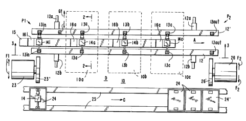
FIG. 1 shows a schematic layout of a portion
of an armature manufacturing assembly line that uses
workstation 10 to concurrently process a group of
armature subassemblies 14. Workstation 10 is
configured to include a sequence of processing units,
for example, three units 10a, lOb, and lOc that process
individual armature subassemblies 14 according to three
consecutive steps or stages of a manufacturing process.
Processing unit l0a may, for example, be a
machine that measures the commutator diameter of an
armature subassembly 14. Unit l0a may use measurement
techniques described, for example, in Sbalchiero et al.
U.S. patent No. 5,454,284. Unit lOb may, for example,
be a cutting machine for turning (i.e., cutting) the
commutator of subassembly 14. Unit lOb may be used to
CA 02342653 2001-04-02
- 10 -
bring commutator diameter values to within desired
product specifications as also described, for example,
in Sbalchiero et al. Further, unit lOc may, for
example, be a brushing machine for removing residual
5 chips and other debris that remain attached to
subassembly 14 after the turning operations of
unit lOb. The units 10a, lOb, and lOc are placed in
sequence along direction A to perform the processing
steps of measuring diameter, turning, and brushing in
10 the same order as these steps are defined in the
manufacturing process for manufacturing an armature.
An individual subassembly 14 passing through
workstation 10 is sequentially processed by units 10a,
lOb, and lOc (i.e., subassembly 14 is first processed
15 by unit 10a, then by unit lOb, and finally by
unit lOc). As the later units in the sequence are
processing subassemblies 14 at later stages of the
manufacturing process, the earlier units are available
to process other subassemblies 14 that are at earlier
20 stages of the manufacturing process. In a loaded
assembly line, i.e., an assembly line with continuous
or steady work flow, subassemblies 14 that have been
processed to different stages of manufacture may be
available at the same time for further processing.
25 Units 10a, lOb, and lOc can substantially concurrently
perform various processing steps of the manufacturing
process on different subassemblies 14 that are
available for processing.
Subassemblies 14 that undergo processing in
30 workstation 10 are positioned on suitable work surfaces
for processing by units 10a, lOb, and lOc. A suitable
work surface may, for example, be a receiving structure
such as receiving structure 13a that holds armature
subassembly 14a in position for processing. Receiving
CA 02342653 2001-04-02
- 11 -
structure 13a may, for example, be a matched pair of
blocks 13' and 13 " illustrated in FIG. 2. Blocks 13'
and 13 " have V-seats 13 " ' (FIG. 3) that have suitable
shapes for seating extreme portions 14' and 14 " of
5 axial shafts prct-u~lrg from center portions 14 " ' of
subassemblies 14. FIG. 2 is a side elevational view,
partly in cross section, showing armature
subassembly 14a that has an armature length L supported
by blocks 13' and 13 " . Extreme portions 14' and 14 "
of axial shafts are seated in V-seats 13 " '.
Receiving structures 13a, 13b, and 13c are
associated with units 10a, lOb, and lOc, respectively.
These receiving structures are supported on a pair of
spaced-apart beam structures running along the
15 workstation 10 in workflow direction, A. Each of
these beam structures may be formed from one continuous
beam or from more than one discontinuous beam segments.
FIG. 1 shows, for example, continuous beams 12 and 12'
that run across workstation 10 in direction A.
20 Blocks 13' and 13 " that form receiving structures 13a,
13b, and 13c are supported on beams 12 and 12',
respectively. Beams 12 and 12' themselves are
adjustably supported on supports 12a and 12b. The
distance between beams 12 and 12' may be changed by
25 moving them laterally on supports 12a and 12b in
directions G1 and G2, respectively. Beams 12 and 12'
also support receiving structures lain and l3out at
reference locations P1 and P2, respectively. Receiving
structures lain and l3out may be used as waiting
30 locations for input to and output from workstation 10,
respectively. The spacing between adjacent receiving
structures 13 is substantially equal.
Armature subassemblies 14 can be processed by
units 10a, lOb, and lOc while they (subassemblies 14)
CA 02342653 2001-04-02
- 12 -
are respectively positioned in receiving
structures 13a, 13b, and 13c corresponding to the
units. Some armature manufacturing process steps
require rotation of armature work pieces during
5 p~~cessing. For example, turning operations performed
by unit lOb require that subassembly 14 rotate while
commutator portions are in contact with a cutting tool
(not shown). In addition to seating extreme
portions 14' and 14 " of axial shafts as described
10 above, V-seats 13 " ' are also suitably shaped to allow
axial rotation of subassemblies 14. Rotational motion
may be imparted to subassemblies 14 by a belt drive
(not shown) in contact with central portion 14 " ' (see,
e.g., Sbalchiero et al.).
15 After a subassembly 14 is processed at one
step of the manufacturing process, it must be moved
forward for processing according to the next step of
the manufacturing process. Movable central beam 15
substantially concurrently transfers a group of
20 subassemblies 14 forward. The group of
subassemblies 14 transferred includes one or more
subassemblies 14 that may be positioned in receiving
structures lain, 13a, 13b, and 13c. With continued
reference to FIG. l, central beam 15 is located between
25 beams 12 and 12'. Central beam 15 has a row of
holders 16. Holders 16 may have any suitable shapes,
for example, semicircular shapes, to support and hold
subassemblies 14 by their central portions 14 " '.
Holders 16 with semicircular shapes are referred to
30 hereinafter as cradles 16. The number of cradles 16 on
beam 15 is one less than the number of receiving
structures 13. Cradles 16 are equally spaced on
beam 15 at substantially the same spacing as receiving
structures 13 are spaced on beams 12 and 12'. Beam 15
CA 02342653 2001-04-02
- 13 -
is parallel to beams 12 and 12' with cradles 16 aligned
with receiving structures 13. The number of
subassemblies that can be held and moved simultaneously
in a group is equal to the number of cradles 16.
FIG. 3 illustrates the relative alignment of cradles 16
with receiving structures 13. FIG. 3 is a side
elevational view from 3-3 of FIG. 1.
FIG. 3 shows central beam 15 at rest at a
starting position. At the starting position, beam 15
is at a vertical height lower than the vertical height
of beams 12 and 12'. The vertical height of beam 15 is
kept sufficiently low so as to avoid any hindrance in
processing subassemblies 14 that are placed in
receiving structures 13. When beam 15 is at the
starting position, cradles 16 are below the plane
formed by receiving structures 13. Also, cradles 16a,
16b, 16c, and 16d are to the left of receiving
structures lain, 13a, 13b, and 13c, respectively.
Receiving structures 13a, 13b, and 13c can have
armature subassemblies 14 with their extreme shaft
portions positioned in V seats 13 "' as suitable for
processing by units 10a, lOb, and lOc. The leftmost
receiving structure lain may hold subassembly 14i as
input ready for processing next by unit 10a. For
clarity these armature subassemblies 14 are not shown
in FIG. 3. As will be described in further detail
below, central beam 15 moves to lift and substantially
simultaneously advance a group of subassemblies 14
through units 10a, lOb and lOc. Each subassembly 14 in
the group is lifted from the particular receiving
structure 13 holding it and advanced to the next
receiving structure 13 in the row of receiving
structures 13.
CA 02342653 2001-04-02
- 14 -
Controlled movement of central beam 15 can be
obtained, for example, through suitable mechanical
linkages. With continued reference to FIG. 3, the left
end of central beam 15 is mechanically hinged to
5 disk 17 at radial point 18. The right end of the beam
is hinged to disk 19 at radial point 18'. Disks 17
and 19 rotate about shafts 20 and 21, respectively.
Radial points 18 and 19 are at substantially equal
radial distances (= R) from shafts 20 and 21,
10 respectively. Shafts 20 and 21 are aligned and placed
at suitable vertical heights to maintain beam 15
substantially parallel to and aligned with beams 12
and 12'.
Suitable power mechanisms may be used to
15 controllably impart rotational motion to either or both
disks 17 and 19. For example, a motor drive (not
shown) may controllably rotate disk 17 in direction B
around shaft 20. Disk 19 may rotate freely on
shaft 21. As disk 19 is mechanically linked to disk 17
20 by central beam 15, disk 19 will rotate in tandem with
disk 17. When disk 17 rotates an amount in
direction B, disk 19 will rotate an equal amount in
direction B'. Further, all portions of central beam 15
(including cradles 16 and the ends of central beam 15)
25 will move by the equal amount along circular
trajectories in direction E. The circular trajectories
are along circles that have a radius substantially
equal to the radial distance, R, between point 18 and
shaft 20. A full revolution of disk 17 around shaft 20
30 in direction B, will cause each portion of central
beam 15 to execute a full circle in direction E. On
executing this full circle, central beam 15 returns to
its starting position (shown in FIG. 3) with cradles 16
to the left of receiving structures 13.
CA 02342653 2001-04-02
- 15 -
The circular motion of beam 15 is designed to
cause a row of subassemblies that may be present in
receiving structures lain, 13a, 13b, 13c, to be
advanced forward along the row of receiving
5 structures 13. The design parameters include, for
example, the spacing of cradles 16, the radial
distance R, and the vertical height of central beam 15
in its starting position relative to beams 12 and 12'.
The transfer of subassemblies 14 effected by
the circular movement of central beam 15 is further
described with reference to FIG. 4. FIG. 4 shows the
transfer of subassembly 14a from receiving
structure 13a to receiving structure 13b. Receiving
structure 13a is immediately to the right of cradle 16a
when beam 15 is at the starting position (FIG. 3).
Receiving structure 13b is the next structure to the
right of receiving structure 13a.
The left portion of FIG. 4 shows central
beam 15 after cradle 16a has rotated forward from the
starting position in direction E by an amount
sufficient to put cradle 16a in contact with central
portions 14 "' of subassembly 14a seated in receiving
structure 13a. Further rotation of cradle 16a in
direction E causes cradle 16a to lift extreme shaft
25 portions 14' and 14 " of subassembly 14a out of
V-seats 13 " '. Cradle 16a then holds subassembly 14a
by supporting central portion 14 " '. As cradle 16a
holding subassembly 14a rotates away in direction E,
receiving structure 13a becomes vacant and available to
30 receive another subassembly 14i (not shown).
Similarly, simultaneous circular motion of cradle 16b
(not shown) removes any subassembly present in
receiving structure 13b. This causes receiving
structure 13b to become available to receive
CA 02342653 2001-04-02
- 16 -
subassembly 14a. Even further rotation of cradle 16a
in direction E places held subassembly 14a in receiving
structure 13b.
The right portion of FIG. 4 shows central
beam 15 after this ever. further rotation.
Subassembly 14a is shown positioned in receiving
structure 13b. Cradle 16a is shown as it is just about
to lose contact with central portion 14 " ' on continued
rotation in direction E while returning to its starting
position (FIG. 3). FIG. 4 also depicts trajectory 22
of the center of an axial shaft end of armature
subassembly 14a as subassembly 14a is transferred from
receiving structure 13a to 13b.
In a similar manner and simultaneously with
the transfer of subassembly 14a from receiving
structure 13a to 13b, the circular motion of central
beam 15 as described above causes subassemblies 14 that
may be present in receiving structures lain, 13b,
and 13c to be transferred to receiving
structures 13a, 13c, and l3out, respectively. As
mentioned earlier, receiving structure l3out can be
used as a waiting location for output subassemblies 14
that have been processed through all three units, 10a,
lOb, and lOc. The transfer of subassemblies 14 forward
through workstation 10 leaves receiving structure lain
vacant. As mentioned earlier, receiving structure lain
can be used to stage input to workstation 10, i.e., to
receive input subassemblies 14 for processing in
workstation 10.
Input and output subassemblies 14 may be
transported to and from work station 10 using prior art
transport systems in which subassemblies 14 are carried
in pallets on belt conveyors (see, e.g., Santandrea
et al.). Using such transport systems,
CA 02342653 2001-04-02
- 17 -
subassemblies 14 processed upstream of work station 10
may be delivered to workstation 10 for further
processing. And subassemblies 14 that have been
processed through workstation 10 may be delivered to
downstream locations for further processing.
Workstation 10 may be integrated for use with
conventional assembly line transport systems (not
shown). Belt conveyors 25 of workstation 10 run in
direction C along front side D of units 10a, lOb,
and lOc. Subassemblies 14 are carried in pallets 24 on
belt conveyors 25. Conventional transfer machines, for
example, pick and place units with grippers that travel
on overhead tracks, may be used to move
subassemblies 14 between pallets 24 and workstation 10.
Subassemblies 14 are moved between pallets 24 and
workstation 10 in a direction which is substantially
parallel to their (subassemblies) longitudinal axis
(e. g., direction F1, FIG. 1), but which at the same
time is also substantially perpendicular to the
direction of work flow in workstation 10 or on
conveyors 25 (e.g., direction C, FIG. 1)
In operation, with continued reference to
FIG. 1, pallet 24 delivering an input subassembly 14
for processing at work station 10 is stopped on belt 25
at reference location Pl. Transfer device 23, for
example, a pick and place unit, using gripper 23'
collects input subassembly 14 from stopped pallet 24
and loads input subassembly 14 in receiving
structure lain. tripper 23' grasps central
portion 14 " ' to pick up input subassembly 14 from
pallet 24. tripper 23' then moves along overhead
linear tracks (not shown) in direction F1 substantially
perpendicular to direction C. tripper 23' stops moving
at a position above receiving structure lain, and then
CA 02342653 2001-04-02
- 18 -
releases subassembly 14 into receiving structure lain.
Empty pallet 24 (with input subassembly 14 picked up)
is released for immediate travel in direction C on belt
conveyors 25.
Empty pallet 24 may be stopped again at or
ahead of reference location P2 to await output
subassembly 14 that has been processed through
units 10a, lOb and lOc. There may be several empty
pallets 24 on belt conveyors 25 at any given time, each
of the several empty pallets 24 having delivered one of
subassemblies 14 that are being concurrently processed
in units 10a, lOb, and lOc. FIG. 1 shows empty
pallet 24' stopped at location P2 in position to
receive an output subassembly 14 from receiving
structure l3out. FIG. 1 also shows two other empty
pallets 24 queued up behind pallet 24'.
Transfer device 26, which may be similar to
transfer device 23, collects output subassembly 14 (not
shown) from receiving structure l3out and transfers it
to empty pallet 24'. In operation, gripper 26' of
transfer device 26 grasps central portion 14 " ' to pick
up output subassembly 14 from receiving
structure l3out. tripper 26' then moves along overhead
linear tracks (not shown) in direction F2 substantially
perpendicular to direction C. tripper 26' stops moving
at a position above empty pallet 24', and then releases
subassembly 14 into empty pallet 24'. tripper 26' then
releases output subassembly 14 into empty pallet 24'.
Pallet 24' carrying output assembly 14 may now be
released for travel to downstream locations. Next, the
other empty pallets 24 that were queuing up behind
pallet 24' may be stopped in turn at location P2 to
pick up subsequent output of workstation 10.
CA 02342653 2001-04-02
- 19 -
This manner of delivering input
subassemblies 14 and picking up output subassemblies 14
makes it possible to load armature subassemblies into
workstation 10 at position P1, at substantially the
5 same time that the armature subassemblies are being
unloaded at position P2. An effective processing time
at workstation 10 is the time between delivery of an
input subassembly and the pick up of an output
subassembly. The loading and unloading operations may
occur even as other subassemblies (e. g., 14a, 14b,
and 14c) are being processed by units 10a, lOb,
and lOc. In an assembly line with a continuous or
steady work flow, simultaneous loading and unloading
subassemblies makes the effective processing time at
work station 10 substantially small. The effective
processing time is about the same time as it takes to
load or unload a subassembly 14 using transfer
devices 23 or 26. The waiting time periods for loading
and unloading from individual step-processing units,
20 for example, as required in prior art assembly lines,
are eliminated. This increases manufacturing
efficiency.
Also, the configuration of workstation 10 as
illustrated in FIG. 1 provides ample and comfortable
operator access to units 10a, lOb and lOc. The
positioning of belt conveyors 25 on front side D of
workstation 10 (alongside beam 12) provides open space
for accessing units 10a, lOb, and lOc. The open space
is not cluttered, for example, with the multiple
30 transfer devices that may be used in prior art assembly
lines for loading and unloading subassemblies from
individual units 10a, lOb, and lOc. Transfer
devices 23 and 26 used with the present configuration
of workstation 10 are to the side of workstation 10
CA 02342653 2001-04-02
- 20 -
away from the open space around units 10a, lOb,
and lOc. Further, transfer devices 23 and 26 have
grippers 23' and 26' that move in directions F1 and F2
on overhead linear tracks and do not impede operator
access to units 10a, 10b, or lOc.
It will be understood that the number of
step-processing units in workstation 10 is, only for
purposes of illustration, shown to be exactly three
(units 10a, lOb, and lOc, FIG. 1). In accordance with
10 the invention, workstation 10 may include a sequence
consisting of any suitable number of step-processing
units. For example, workstation 10 may include two
separate units for coarse turning and fine turning
operations (instead of a single turning unit, i.e.,
15 unit lOb) so that the total number of units increases
to four. The suitable number of units in the sequence
may be as few as one. For example, workstation 10 may
include only an inspection unit. The single inspection
unit may be used, for example, to inspect the quality
20 of a sample of subassembly work flow in an assembly
line. Subassemblies that are not part of the sample
may, optionally, be transported directly from upstream
locations to downstream locations on conveyors 25
bypassing the inspection unit.
25 Beams 12 and 12' that support receiving
structures 13, and beam 15 that supports cradles 16 may
have suitable constructions so that their lengths
(i.e., the number of receiving structures 13 and
cradles 16, respectively) can be adjusted according to
30 the number of step-processing units in workstation 10.
Reference locations P1 and P2 at which subassemblies
are respectively loaded and unloaded may also be
suitably adjusted to correspond to the number of
step-processing units in workstation 10.
CA 02342653 2001-04-02
- 21 -
Further, a previously described feature of
the configuration of workstation 10 enables use of
workstation 10 for processing armature subassemblies of
different lengths at workstation 10. As mentioned
earlier, beams 12 and 12' can be moved laterally in
directions Gl and G2 on support structures 12a and 12b
(FIG. 1). By such movement the distance between
beams 12 and 12' may be suitably adjusted so that
blocks 13' and 13" of receiving structures 13 are
10 appropriately spaced to seat an armature subassembly of
a given length L (FIG. 2). This feature of
workstation 10 allows workstation 10 to be integrated
into manufacturing assembly lines that batch-process
armature subassemblies of different lengths. Such
15 assembly lines may use prior art adjustable transport
systems that can transport subassemblies of different
sizes. For example, Santandrea et al. disclose
adjustable pallets (similar to pallet 24, FIG. 1) for
transporting subassemblies of different sizes.
20 Adjusting stations such as disclosed, for example, by
Santandrea et al., may be used to adjust pallet size
upstream of workstation 10 to accommodate subassemblies
of different lengths. In these adjustable transport
systems belt conveyors (similar to belt conveyors 25,
25 FIG. 1) may be used to deliver batches of different
length subassemblies to workstation 10. Workstation 10
may be converted to accommodate different length
subassemblies during the idle times existing between
manufacturing of the batches.
30 Another embodiment of the present invention
is described below with reference to portions of a
workstation illustrated in FIGS. 5 - 7.
FIG. 5 is a plan view of portions of
workstation 50. FIG. 6a is a side elevational view of
CA 02342653 2001-04-02
- 22 -
workstation 50. In both FIGS. the workflow is in the X
direction from right to left. Workstation 50 includes
table 60 with top table top 61 supported, for example,
off an assembly line floor, by legs 62. Aperture 63
5 allows passage of processing-related debris from above
table top 61 to below table top 61.
Workstation 50 includes a sequence of
step-processing units. The sequence may include, for
example, coarse turning unit 50a and fine turning
10 unit 50b. Units 50a and 50b may rest directly on table
top 61. For clarity, other step-processing units that
may be included in the sequence are not shown.
Workstation 50 includes a row of equally spaced
receiving structures 13. Each receiving structure 13
15 includes a pair of spaced-apart blocks 13' and 13 "
with suitably shaped seats 13 " ' to hold
subassemblies 14 (FIG. 2). Walking beam 55 supports a
row of cradles 56 aligned with the row of receiving
structures 13. Walking beam 55 operates above table
20 top 61 and between blocks 13' and 13 " of receiving
structures 13. Controlled movement of walking beam 55
in an approximately rectangular path (as will be
further described below with reference to FIG. 7)
advances subassemblies 14 along the row of receiving
25 structures 13. Subassemblies 14 are advanced in the
direction of workflow through workstation 50. The row
of receiving structures 13 may include receiving
structures lain and l3out for holding input
subassemblies transported to workstation 50 and output
30 subassemblies for transport from workstation 50,
respectively. The row also includes receiving
structures 13k, 131, 13m, and 13n that can hold
subassemblies 14 in position for processing by
associated step-processing units in workstation 50.
CA 02342653 2001-04-02
- 23 -
For example, units 50a and 50b perform turning
operations on commutator portions of subassemblies 14
positioned in receiving structures 13k and 13m,
respectively.
5 Units 50a and 50b may be conventional turning
units. Units 50a and 50b use conventional tool bits 51
having cutting edges, for turning. Tool bits 51 are
mounted on conventional motorized X-Y translation
stages using conventional mounting fixtures 52. For
10 clarity, tool bit 51 associated with unit 50b is not
shown. Upper and lower carriages 53u and 531 of the
X-Y translation stages are driven by motors 53m. Upper
carriages 53u are movable in directions Y, and can be
used to drive cutting tools 51 along the length, for
15 example, of commutator portions of subassemblies 14
that are being turned. Lower carriages 531 are movable
in directions X, and can be used to drive cutting
tool 51 to suitable positions to obtain desired cutting
depths. The range of travel of carriages 53u and 531
20 in the X and Y directions defines a work zone or region
over which units 50a and 50b are capable of cutting
operations. Aperture 63 may be suitably placed
directly below this zone or region. Burrs and other
cutting debris resulting from the cutting operations
25 fall below table top 61 through aperture 63. Duct 64
guides the debris into burr collector 65. Collector 65
may be placed, for example, underneath table top 61.
Receiving structures 131 and 13m associated
with units 50a and 50b, respectively, are supported on
30 of a pair of linear translation stages 56 and 56'.
Stages 56 and 56' have movable carriages 57 and 57',
respectively. Blocks 13' (FIG. 2) of receiving
structures 131 and 13m may, for example, be supported
on carriage 57, while blocks 13 " are supported on
CA 02342653 2001-04-02
- 24 -
carriage 57'. Linear translation stages 56 and 56' may
themselves rest on table top 61. Each of linear
translation stages 56 and 56' includes frame 56f
holding guide rods 56g. Carriages 57 and 57'
5 adjustably slide on guide rods 56g in directions Y.
Suitable drive mechanisms may be used to adjust the
position of carriages 57 and 57'. For example, linear
translation stages 56 and 56' may use manual screw
drives. The manual drives may include threaded
10 bars 56t connected to threaded bushings (not shown) on
carriages 57 and 57'. Turning threaded bars 56t
moves carriages 57 and 57' in directions Y.
Receiving structures (e. g., lain, 13k, 13n,
and l3out) other than those supported on carriages 57
15 and 57' may be supported on laterally spaced-apart beam
structures running along the workstation 50 in the
direction of the work flow. Each of these beam
structures may be formed from one continuous beam or
from more than one discontinuous beam segments. FIG. 5
20 shows, for example, receiving structures lain, 13k,
13n, and l3out supported on pairs of substantially
parallel beams 58 and 58'. Beams 58 extend in
directions X through workstation 50 from both sides of
carriage 57. Similarly, beams 58' extend in
25 directions X through workstation 50 from both sides of
carriage 57'. Beams 58 and 58' may optionally be
attached to carriages 57 and 57', respectively. For
example, FIG. 5 shows beams 58 and 58' mechanically
coupled to carriages 57 and 57' through isolation
30 blocks 59. Beams 58 and 58' may also be suitably
shaped to provide step-processing units adequate
working space to process subassemblies 14. For
example, FIG. 6a shows cutouts 58c in beams 58.
Cutouts 58c allow upper carriages 53u to travel in
CA 02342653 2001-04-02
- 25 -
directions Y laterally past beams 58 for processing
subassemblies 14 positioned in receiving structures 131
and 13m. Carriages 531 remain movable in directions X
alongside an exterior surface of beam 58.
5 At ends remote from carriages 57 and 57',
beams 58 and 58' have attached bushings 58b that can
adjustably slide in directions Y on horizontal
adjustment guides 58g. Guides 58g are held at a
suitable vertical distance above table top 61 by
10 supports 58s. The vertical distance is such that the
row of receiving structures 13 is in a level plane
above table top 61.
The lateral spacing between seats 13 " ' on
blocks 13' and 13 " of receiving structures 13 may be
15 suitably adjusted to match the length, L, of
subassemblies 14 (FIG. 2) that are being processed by
workstation 50. The spacing may be adjusted by
operation of linear translation stage 56 and 56'. By
turning threaded bars 56t, carriages 57 and 57' may be
20 moved to appropriate positions in directions Y so that
blocks 13' and 13 " in receiving structures 131 and 13m
are spaced a suitable distance apart. Since beams 58
and 58' are mechanically coupled to carriages 57
and 57', they (beams 58 and 58') move together with
25 carriages 57 and 57'. As a result, the spacings
between blocks 13' and 13" in receiving
structures lain, l3out, 13k, and 13n (supported on
beams 58 and 58') are also simultaneously adjusted to
match the length, L, of subassemblies 14.
30 Linear stages 56 and 56' may be operated to
adjust or fine-tune the spacing of blocks 13' and 13 "
even while subassemblies 14 are positioned in receiving
structures 13, for example, receiving structures 131
and 13m associated with turning units 50a and 50b,
CA 02342653 2001-04-02
- 26 -
respectively. Fine-tuning the spacing may, for
example, accommodate variations in the length of
subassemblies 14 in the work flow, and be desirable for
turning operations performed by units 50a and 50b.
5 Operation of linear stages 56 and 56', and
also the operation of units 50a or 50b may generate
mechanical vibrations. To reduce transmission of these
mechanical vibrations through beams 58 and 58' to other
parts of workstation 50, isolation blocks 59 may have
10 any suitable vibration-damping construction. An
example of such a construction of blocks 59 is shown in
FIG. 6b (taken along direction A-A in FIG. 5). FIG. 6b
shows an end of beam 58 coupled to carriage 57 using
conventional metal bolt 66 and core insert 67.
15 Space 68 between core insert 67 and carriage 57 is
packed with suitable anti-vibration material, for
example, anti-vibration silane blocks and rubber rings.
Isolation blocks 59 also serve to
substantially isolate subassemblies 14 positioned in
20 receiving structures 13m and 131 from mechanical
vibrations generated in other parts of workstation 50.
For example, loading and unloading operations that
involve depositing input subassemblies 14 into
receiving structures lain and picking up output
25 subassemblies 14 from receiving structures l3out,
respectively, may generate mechanical vibrations. In
the operation of workstation 50, these loading and
unloading operations may occur while other
subassemblies 14 are being turned by units 50a and 50b.
30 Isolation blocks 59 reduce transmission of loading and
unloading vibrations to receiving structures 13m
and 131. The reduced transmission of vibrations
enables turning operations to proceed substantially
CA 02342653 2001-04-02
- 27 -
unaffected by contemporaneous loading or unloading
operations.
It will be understood that other features of
the configuration of work station 50, such as table 60
5 are also designed to minimize vibraticns and to provide
mechanical stability for processing operations. For
example, in turning operations, the effect of floor and
machine vibrations is often proportional to the
distance between the cutting tool bit and the base of
10 the turning unit. In workstation 50, the bases of
turning units 50a and 50b do not rest on the assembly
line floor but rest on table top 61. The relatively
smaller distance, for example, between cutting tool 51
and the base of unit 50a, reduces the effect of
15 vibrations on cutting operations.
Further, other components of workstation 50
such as other step-processing units, linear translation
stages 56 and 56', and beams 57 and 57' are all
supported in common on table top 61. All of the
20 components supported by table top 61 may move
substantially in unison with table top 61 in response
to floor vibrations. This is unlike the conventional
case where components are supported directly on the
assembly line floor. In that case, different
25 components may respond differently to floor vibrations
and may exhibit large relative displacements with
respect to each other. The movement in unison of
components supported by table top 61 reduces the
relative displacement of components and increases
30 mechanical stability which is desirable for processing
operations.
Further, at least in part to avoid
undesirable coupling of vibrations, walking beam 55 and
associated mechanical linkages for its controlled
CA 02342653 2001-04-02
- 28 -
motion may be physically unconnected from table 60.
For example, FIG. 7 shows walking beam 55 and
associated mechanical linkages physically unconnected
from table 60 with only vertical guide rods 73 passing
through table top 61.
With reference to FIG. 7, walking beam 55
supports a row of cradles 56 aligned with the row of
receiving structures 13 (FIG. 5). FIG. 7 is a side
elevational view taken along line 7-7 in FIG. 5. For
10 clarity the row of receiving structures 13 and other
components of workstation 50 such as beams 58', and
linear translation stage 56', are not shown.
Cradles 56 have suitable shapes (e. g., semicircular
shapes) to lift and hold subassemblies 14. Beam 55 is
supported on a pair of linear slide assemblies 70a.
Assemblies 70a may be dovetail slides, recirculating
ball tracks, or any other type of conventional slide
assemblies, that allow beam 55 to move in directions X.
FIG. 7 shows, for example, a pair of dovetail
20 slides 71a attached to ends of beam 55. Slides 71a
rest slidably in horizontal tracks in guides 72a.
Controlled linear movement of beam 55 in
directions X, for example, from positions 2 to 4 or
vice versa, may be obtained using a suitable power
mechanism, for example, air cylinder 73a. A side of
cylinder 73a is attached, for example, to rightmost
guide 72a. On the other side of cylinder 73a, cylinder
rod 74 is mechanically connected to beam 55 through
appendix 75a. When air cylinder 73a is activated,
30 cylinder rod 74 extends toward the left, and beam 55
slides on guides 72 toward position 2. Conversely,
when air cylinder 73a is deactivated, cylinder rod 74
retreats toward the right, and beam 55 slides toward
position 4.
CA 02342653 2001-04-02
- 29 -
Slide assemblies 70a are supported at a
suitable distance above table top 61 on vertical guide
rods 76. Guide rods 76 move vertically when activated
by suitable drive mechanisms placed underneath table
5 top 61. FIG. 7 shows pairs of vertical guide rods 76
extending downwards from the leftmost and the rightmost
guides 72a. The pairs pass through table top 61 and
terminate in structures with rollers 77. Rollers 77
are held slidably in slots 78 of drive beam 79.
10 Slots 78 have substantially identical shapes so that
when rollers 77 slide in slots 78 both pairs of guide
rods 76 remain substantially vertical and parallel to
each other. The shapes have low positions 78' at one
end and high positions 78 " at the other end. When
15 rollers 77 are at low positions 78', beam 55 supported
on top of guide rods 76 is at lower vertical
position 3. And when rollers 77 are at upper
positions 78 " , beam 55 is at upper vertical
position 1.
20 Drive beam 79 is supported on a pair of
linear slide assemblies 70b that allow beam 79 to move
in directions X. Linear slide assemblies 70b may be
any suitable conventional linear slides, and may, for
example, be similar to slide assemblies 70a. FIG. 7
25 shows a pair of dovetail slides 71b attached to
beam 79. Slides 71b rest slidably in horizontal tracks
in guides 72b. Guides 72b are themselves placed on the
assembly line floor underneath table top 61.
Controlled upward or downward movement of
30 beam 55 in directions Z, for example, from positions 3
to 1 or vice versa, may be obtained using a suitable
power mechanism, for example, air cylinder 73b (similar
to air cylinder 73a) to move beam 79. One side of
cylinder 73b is attached to floor support 73b'. On the
CA 02342653 2001-04-02
- 30 -
other side of cylinder 73b, a cylinder rod (not shown)
is mechanically connected to beam 79 through
appendix 75b. When air cylinder 73b is activated, the
cylinder rod extends toward the left causing beam 79 to
slide to the left. As beam 79 slides to the left,
rollers 77 slide to upper positions 78 " of slot 78,
and cause beam 55 to move to upper vertical position 1.
Conversely, when air cylinder 73b is deactivated the
cylinder rod retreats toward the right causing beam 79
to slide to the right. As beam 79 slides to the right,
rollers 77 slide to lower positions 78' of slot 78, and
cause beam 55 to move to lower vertical position 3.
Vertical positions 1 and 3, and horizontal
positions 2 and 4 of beam 55 are designed such that
sequential movement of beam 55 between the positions
causes a group of subassemblies that may be present in
the row of receiving structures 13 to be advanced
forward along the row. In position 3, cradles 56 are
aligned with but below the horizontal plane of
20 receiving structures 13. In position 1, cradles 56 are
aligned with but above the horizontal plane of
receiving structures 13.
In operation, vertical movement of beam 55
from position 3 to position 1 causes cradles 56 to move
upwards lifting subassemblies 14 out of receiving
structures 13. Next, horizontal movement of beam 55
from position 4 to position 2 advances cradles 56 to a
position above the adjoining receiving structures 13.
Further, downward movement from position 1 to
30 position 3 causes cradles 56 to move downwards
redepositing held subassemblies 14 in the adjoining
receiving structures 13 underneath. Finally,
horizontal movement from position 2 to position 4
causes beam 55 to return to a starting position with
CA 02342653 2001-04-02
- 31 -
cradles 56 underneath the row of receiving
structures 13.
One skilled in the art will appreciate that
the present invention can be practiced by other than
5 the described embodiment, which is presented for
purposes of illustration and not of limitation.