Language selection

Search

Patent 2342900 Summary

Third-party information liability

Some of the information on this Web page has been provided by external sources. The Government of Canada is not responsible for the accuracy, reliability or currency of the information supplied by external sources. Users wishing to rely upon this information should consult directly with the source of the information. Content provided by external sources is not subject to official languages, privacy and accessibility requirements.

Claims and Abstract availability

Any discrepancies in the text and image of the Claims and Abstract are due to differing posting times. Text of the Claims and Abstract are posted:

  • At the time the application is open to public inspection;
  • At the time of issue of the patent (grant).
(12) Patent Application: (11) CA 2342900
(54) English Title: ROCK DRILLING DEVICE
(54) French Title: DISPOSITIF DE PERFORATION DE ROCHES
Status: Deemed Abandoned and Beyond the Period of Reinstatement - Pending Response to Notice of Disregarded Communication
Bibliographic Data
(51) International Patent Classification (IPC):
  • E21B 19/08 (2006.01)
  • E21B 15/00 (2006.01)
  • E21B 19/084 (2006.01)
(72) Inventors :
  • SAF, FREDRIK (Sweden)
(73) Owners :
  • ATLAS COPCO ROCK DRILLS AB
(71) Applicants :
  • ATLAS COPCO ROCK DRILLS AB (Sweden)
(74) Agent: SMART & BIGGAR LP
(74) Associate agent:
(45) Issued:
(86) PCT Filing Date: 1999-08-18
(87) Open to Public Inspection: 2000-03-16
Availability of licence: N/A
Dedicated to the Public: N/A
(25) Language of filing: English

Patent Cooperation Treaty (PCT): Yes
(86) PCT Filing Number: PCT/SE1999/001389
(87) International Publication Number: SE1999001389
(85) National Entry: 2001-03-02

(30) Application Priority Data:
Application No. Country/Territory Date
9802963-0 (Sweden) 1998-09-03

Abstracts

English Abstract


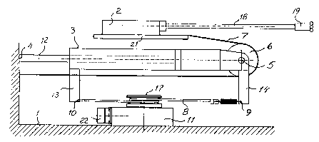
Rock drilling device comprising a feed beam (1) and a rock drilling machine
(2) movable along the feed beam. The rock drilling machine is fed along the
feed beam (1) by means of a feed line (7) which is routed over a sheave (6)
arranged at the movable end (5) of a pressure medium cylinder (3). A further
line (8) is arranged between two points (9, 10) which are fixed relative to
the movable end (5) of the pressure medium cylinder (3). The further line (8)
is connected with a measuring device (11) which is fixedly arranged on the
feed beam (1) for measuring the displacement of the rock drilling machine (2)
along the feed beam.


French Abstract

L'invention se rapporte à un dispositif de perforation de roches comportant une poutre de guidage (1) et une machine perforatrice de roches (2) mobile le long de la poutre de guidage. Ladite machine perforatrice de roches se déplace le long de la poutre de guidage (1) au moyen d'une ligne de guidage qui passe sur un réa (6) disposé au niveau de l'extrémité mobile (5) d'un cylindre (3) de milieu de pression. Une autre ligne (8) est disposée entre deux points (9, 10) qui sont fixés relativement à l'extrémité mobile (5) du cylindre (3) de milieu de pression. Cette autre ligne (8) est reliée à un dispositif de mesure (11) qui est attaché de manière fixe à la poutre de guidage (1) pour permettre la mesure du déplacement de la machine perforatrice de roches (2) le long de la poutre de guidage.

Claims

Note: Claims are shown in the official language in which they were submitted.

3
Claim:
1. Rock drilling device comprising a feed beam (1), a rock drilling machine
movable to-and-fro along the feed beam, a pressure medium cylinder (3) of
which one end
(4) is fixed relative to the feed beam (1) and the other end (5) is movable
relative to the
feed beam and carries a sheave (6) over which a feed line (7) is routed, and
that said feed
line (7) is connected with the feed beam (1) and with the rock drilling
machine (2),
characterized in that a further line (8) is arranged between two points (9,10)
which
are fixed relative to the movable end (5) of the pressure medium cylinder (3)
and that said
further line (8) is connected with a measuring device (11) which is fixedly
arranged on the
feed beam (1).

Description

Note: Descriptions are shown in the official language in which they were submitted.


CA 02342900 2001-03-02
WO 00/14376 PCT/SE99/01389
Rock drillin dg evice
The present invention relates to a rock drilling device. More particularly the
invention
relates to a rock drilling device provided with a measuring device for
measuring the
movement of a rock drilling machine along a feed beam.
In a previously known device of the above mentioned kind, see WO 94/06999, fig
4, the
movement of the rock drilling machine along the feed beam is sensed by a
measuring
means which is arranged on the rock drilling machine. A drawback with this
device is that
the measuring means moves with the rock drilling machine in its movement along
the feed
beam. The measuring cables therefore must be lead away via the usual hose
reel. This
means that the measuring cables must be placed among the pressure medium
conduits
which supply driving medium to the rock drilling machine. Since these conduits
contain
fluid of pulsating pressure the conduits will vibrate which can damage the
measuring
cables.
The present invention, which is defined in the subsequent claim, aims at
achieving a rock
drilling device where the above mentioned problems with damages on the
measuring
cables are avoided through arranging the measuring device stationary on the
feed beam,
through which the measuring cables need not be arranged together with the
pressure
medium conduits.
An embodiment of the invention is described below with reference to the
accompanying
drawing in which fig 1 shows a rock drilling device according to the
invention. Fig 2 shows
schematically a part of the device according to fig 1 with certain parts taken
away for
increased clarity.
The device shown in the drawing comprises a feed beam 1 intended to be carried
by a not
shown drill rig in the usual manner. A rock drilling machine 2 is arranged on
a slide 21
which is movable along the feed beam 1. A drill string 18 including a drill
bit 19 is
connected to the rock drilling machine 2. The rock drilling machine is
displaced by means
of a pressure medium cylinder 3 and a feed line 7. In practice, not shown in
fig 2, there is

CA 02342900 2001-03-02
WO 00/14376 PCT/SE99/01389
2
also a feed line for the return feed of the rock drilling machine. The
pressure medium
cylinder 3 has a first end 4 which is fixed relative to the feed beam 1 and a
second end 5
which is movable relative to the feed beam 1. In the shown example it is the
piston rod 12
of the pressure medium cylinder 3 which is fixed relative to the feed beam 1.
It is also
possible to turn the pressure medium cylinder 3 such that the movable end 5 is
arranged on
the piston rod 12. The movable end 5 of the pressure medium cylinder 3 carries
a sheave 6.
The feed line 7 which is routed over the sheave 6 is with its one end fixed to
the feed beam
1 and with its other end connected with the slide 21 of the rock drilling
machine 2. With
this arrangement the rock drilling machine 2 is driven along the feed beam 1
with twice as
high speed as the movable end 5 on the pressure medium cylinder 3. The rock
drilling
device is provided with a hose reel 15 and a drill support 16 at the middle of
the drill string
18. The hose reel 15 is in fig 2 marked by the support 13 and the drill
support 16 by the
support 14. This means that the hose reel 15 and the drill support 16 are
driven along the
feed beam 1 with the same speed as the movable end 5 of the pressure medium
cylinder 3
in the usual way. The supports 13,14 are provided with points 9,10 between
which a further
line 8 is arranged. This further line is routed, one or more turns, about a
wheel 17 on a
measuring device 11 which is fixed on the feed team 1. The measuring device 11
delivers
pulses corresponding to the displacement of the rock drilling machine 2 along
the feed
beam 1. Since the measuring cables are connected to a socket 22 on the
measuring device
11 the measuring cables are fixed relative to the feed beam 1 and are thus not
exerted to the
loads which vibrating pressure medium hoses cause. The position of the rock
drilling
machine 2 along the feed beam 1 is measured by counting the pulses from the
measuring
device 11.

Representative Drawing
A single figure which represents the drawing illustrating the invention.
Administrative Status

2024-08-01:As part of the Next Generation Patents (NGP) transition, the Canadian Patents Database (CPD) now contains a more detailed Event History, which replicates the Event Log of our new back-office solution.

Please note that "Inactive:" events refers to events no longer in use in our new back-office solution.

For a clearer understanding of the status of the application/patent presented on this page, the site Disclaimer , as well as the definitions for Patent , Event History , Maintenance Fee  and Payment History  should be consulted.

Event History

Description Date
Inactive: IPC from MCD 2006-03-12
Application Not Reinstated by Deadline 2005-08-18
Time Limit for Reversal Expired 2005-08-18
Deemed Abandoned - Failure to Respond to Maintenance Fee Notice 2004-08-18
Inactive: Abandon-RFE+Late fee unpaid-Correspondence sent 2004-08-18
Inactive: Cover page published 2001-05-29
Inactive: First IPC assigned 2001-05-23
Letter Sent 2001-05-10
Inactive: Notice - National entry - No RFE 2001-05-10
Application Received - PCT 2001-05-05
Application Published (Open to Public Inspection) 2000-03-16

Abandonment History

Abandonment Date Reason Reinstatement Date
2004-08-18

Maintenance Fee

The last payment was received on 2003-07-08

Note : If the full payment has not been received on or before the date indicated, a further fee may be required which may be one of the following

  • the reinstatement fee;
  • the late payment fee; or
  • additional fee to reverse deemed expiry.

Patent fees are adjusted on the 1st of January every year. The amounts above are the current amounts if received by December 31 of the current year.
Please refer to the CIPO Patent Fees web page to see all current fee amounts.

Fee History

Fee Type Anniversary Year Due Date Paid Date
Registration of a document 2001-03-02
Basic national fee - standard 2001-03-02
MF (application, 2nd anniv.) - standard 02 2001-08-20 2001-07-04
MF (application, 3rd anniv.) - standard 03 2002-08-19 2002-07-08
MF (application, 4th anniv.) - standard 04 2003-08-18 2003-07-08
Owners on Record

Note: Records showing the ownership history in alphabetical order.

Current Owners on Record
ATLAS COPCO ROCK DRILLS AB
Past Owners on Record
FREDRIK SAF
Past Owners that do not appear in the "Owners on Record" listing will appear in other documentation within the application.
Documents

To view selected files, please enter reCAPTCHA code :


To view images, click a link in the Document Description column. To download the documents, select one or more checkboxes in the first column and then click the "Download Selected in PDF format (Zip Archive)" or the "Download Selected as Single PDF" button.

List of published and non-published patent-specific documents on the CPD .

If you have any difficulty accessing content, you can call the Client Service Centre at 1-866-997-1936 or send them an e-mail at CIPO Client Service Centre.


Document
Description 
Date
(yyyy-mm-dd) 
Number of pages   Size of Image (KB) 
Representative drawing 2001-05-28 1 11
Abstract 2001-03-01 1 58
Description 2001-03-01 2 94
Drawings 2001-03-01 1 33
Claims 2001-03-01 1 19
Reminder of maintenance fee due 2001-05-08 1 111
Notice of National Entry 2001-05-09 1 193
Courtesy - Certificate of registration (related document(s)) 2001-05-09 1 113
Reminder - Request for Examination 2004-04-19 1 116
Courtesy - Abandonment Letter (Maintenance Fee) 2004-10-12 1 178
Courtesy - Abandonment Letter (Request for Examination) 2004-10-26 1 167
PCT 2001-03-01 7 318