Note: Descriptions are shown in the official language in which they were submitted.
CA 02343146 2001-03-07
WO 00/13956 PCT/GB99/02988
SNOW-TYPE 13IRE
This invention relates to a snow-type bike sometimes
known as a ski bob or snowscoot.
Snow-type bikes have become popular with snow sport
enthusiasts, and a known bike, more particularly a ski bob, is
shown in Figure 1. This known sriow-type bike has a frame 1
formed of a crossbar 2 to which is secured a seat pillar 3 and
a handlebar headset 4. Pivotally mounted in the headset is a
handlebar column 5, the lower end of which is pivotally
mounted in the headset and the upper end of the column 5 is
secured to a pair of user-operable handlebars 6. The
handlebars are connected through the column 5 in the headset 4
to a column 7 that is connected via a suspension unit 8 to a
forward ski 9. The pillar 3 is attached to a seat saddle 10
and the saddle is attached by a strut 11 to a rearward end of
a rear ski 12 through a suspension unit 14, the forward end of
the rear ski 12 being attached by a support member 13 to the
headset. The terms "forward" and "rear" used herein refer to
directions in use, i.e. leading and trailing. Such a known
ski bob is ridden by a user who wear-s a pair of foot skis 15
so as to stabilise the user. Thus, in use, the ski bob is
ridden and steered by a user via the forward ski 9 and, of
necessity, has their feet on the siiow through the intermediary
of the foot skis for stability.
A further form of snow-type bike, which is known as a
snowscoot, is shown in Figure 2. In this form of device,
there is an inverted Y-shaped frame 20 connected to a headset
24 which pivotally locates a column 25 supporting a pair of
handlebars 26. The lower end of the column 25 is connected to
a pair of forks 27 with a lower end of the forks being
connected to a forward ski 29. The frame 20 has a frame
member 21 laterally centrally seci.zred to a forward end of a
rear ski 30 and another frame member 22 laterally centrally
,CA 02343146 2006-05-25 ~
-2-
connected toward a rearward end of the rear ski 30. Th= rear
suooorts a platform 31 having an upturned rear e~d and
end is located a strap 32 for securing a user's
=n Lse located one on each side of the frame member 22.
?n. use of the device of Figure 2, a user stands with both fee_
c..: rear ski 30 and steers the device by the handlebars 26.
It is known that users of BMX'bikes like to jump over
cb~ a~1es and to perform freestyle movements of the bikes and
i0 of =heT.selves when in mid-air, and a similar desire exists
with snow enthusiasts. Neither of the forementioned devices
are able to permit such freestyle use to the level and style
found in BriX-ing. In the former device of Figure 1, a user,
cf necessity, has to use a pair of foot skis because the rear
15 ski 12 is too narrow to support a user, and in the snowscoot
of Figure 2 a user's feet are secured to the rear ski which
may cause a user injury in a crash. Furthermore, the
snowscoot of Figure 2 does not have a seat.
US-A-4,097,055, FR-A-2 521 937 and US-A-3,870,330
20 disclose a snow-type bike having a frame supporting a seat for
a user and located beneath the seat is a rear ski member. A
forward ski member is attached to a handlebar steering member.
1-oc*_r?sts extend on each side of the fra:ne at a location
between the seat and the plane of the rear ski me,-nber.
25 ::oNever, in such prior art arrangements the rear ski member
-fixedly secured to the frame and, as a result, not only are
sush snow-'yp e bikes uncom -=ortable but also the rear ski
r,ie.m'aer tends to fracture i n use.
The present inventior. seeks to at least partially
30 mitigate the foregoing disadvantages.
According to a first aspect of this invention there is
pr=~.vld _d a si:o'n'-tVpv bike for use 1n snow comprising i=ame
* Trademark
11-09-2000 CA 02343146 2001-03-07 GB 009902988
-2A-
means supporting seat means for a user and steering means,
said frame means having a longitudinal axis, a rear ski member
attached to said frame means, a forward ski member attached to
said steering means, the attachment of' said rear and forward
ski members being on said longitudinal. axis and the attachment
of the frame means to the rear ski member being at
longitudinally spaced locations of the: frame means, and
footrest means extending on each side of the frame means at a
location between said seat means and t:he plane of said rear
ski member, characterised by means being provided for
permitting the rear ski member to flex between said spaced
locations.
Preferably, footrest means is fixedly located on said
frame means or on said rear ski member.
Preferably, the forward and rear ski members have a width
two or more times, preferably four tirnes, the width of a
normal recreation ski.
Conveniently, the front and rear ski members have the
same width.
AMENDED SHEET
CA 02343146 2001-03-07
WO 00/13956 PCT/GB99/02988
3
Preferably, said frame means comprises first and second
frame members each joined at a respective first end thereof to
a headset member and joined at a second, opposed end thereof
to a third frame member, said third frame member being located
substantially parallel to said rear ski member, said third
frame member carrying said footrest means.
Preferably, the footrest means comprise a pair of
footrests extending one on each sidE, of said frame means.
Conveniently, the vicinity of the juxta position of the
first and third frame members and the second and third frame
members forms a securing location of the frame means to the
rear ski member.
Advantageously, the first frame member supports the seat
means.
Preferably, the headset pivotally supports the steering
means which comprises a pair of handlebars attached to at
least one fork member, a lower end of at least one fork member
being attached to the forward ski member.
Advantageously, a pair of fork members are provided.
Advantageously, the handlebars at a location in the
vicinity of the headset are shaped and spaced to accommodate a
drag lift or other tow lift.
Preferably, the fork members are pivotally attached
directly or indirectly to the forward ski member.
Advantageously, the forward ski member is pivotally
attached to the fork members for movement about at least one
of an axis which is transverse to the longitudinal direction
of the frame means and an axis which is along the
longitudinal direction of the frame means, both said axes
being defined when the forward and rear ski members are
aligned.
Advantageously, the rear ski member is pivotally
attached to the frame means for movement about a
longitudinal axis of the frame mearis.
11-09-2000 CA 02343146 2001-03-07 GB 009902988
-4-
In an embodiment of the inventio,n the frame means is
attached to the rear ski member by suspension means and,
advantageously, the steering means may be attached to the
forward ski member through the intermediary of one or more
suspension members.
Where the front ski member is pivotally connected to the
steering means, preferably means are provided for damping
pivotal motion of said front ski member.
Advantageously, the frame means is attached to the rear
ski member at longitudinally spaced locations of the frame and
means are provided for permitting the rear ski member to flex
between said spaced locations.
Preferably, said footrest means include an abrasive upper
foot engaging surface.
In this invention the footrest means are located above
the rear ski member giving substantial room for a user's feet
to extend over the edge of the rear ski member, if desired,
without the user's feet hitting the ground. A user is, thus,
able to stand on the footrest means with their legs slightly
apart giving a more natural stance during normal riding. The
invention has the following advantages:
AMENDED SHEET
-03-07-2000 CA 02343146 2001-03-07 GB 009902988
. ,~ .. .... .. .... .. ..
...~~ . . . ; : .= . .. .
..õ . . . .. ,
. õ . . '. . . . . .. .
. ., . .. , . . . . .. .
. ., .. .. . .. . . .. ..
4A -
1. A user can absorb greater vertical impact from a
jump without exerting masses of forward or backward lean which
impairs control and stability.
2. A user can take greater vertical impact from a
jump, absorbing the pressure through the bike and the user's
legs simultaneously.
3. A user can ride over rough ground more freely.
4. A user's f eet are not restricted by skis, as in
Figure 1, or a strap, as in Figure 2, so that a user is able
to perform a greater number of popular freestyle manoeuvres.
5. Without the requirement of skis on a user's feet,
as in Figure 1, or the strap of Figure 2, a user is less
likely to sustain leg injury.
6. A user who has larger feet or who is wearing
warmer, bulkier footwear will not have their performance
AMENDED SHEET
CA 02343146 2001-03-07
WO 00/13956 PCT/GB99/02988
restricted as in the prior art.
The invention will now be described, by way of example,
with reference to the accompanying drawings in which:
Figure 1 shows a perspective view of a prior art snow-
5 type bike known as a ski bob,
Figure 2 shows a perspective view of a ariother prior art
snow-type bike known as a snowscoot,
Figure 3 shows a perspective view of a snow-type bike in
accordance with this invention, knotim as a BOARDBIKErm,
Figure 4 shows a partial side view of the snow-type bike
of Figure 3,
Figure 5 shows a perspective view of a second embodiment
of the present invention,
Figures 6(a) and 6(b) show mtitually orthogonal partial
views of an alternative embodiment of a snow-type bike of this
invention having a damper for pivotal motion of the forward
ski,
Figure 7 shows a partial side view of a rear ski member
securement to a frame in an alternative embodiment of the
snow-type bike of this invention, ar.Ld
Figure 8 shows a perspective view of a bracket used in
the embodiment of Figure 7.
In the Figures like referertce numerals denote like
parts.
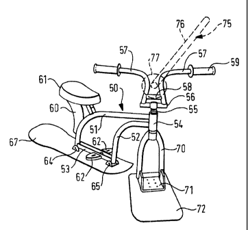
The snow-type bike shown in Figures 3 and 4 has a frame
50 formed of a first member 51 which forms a cross bar and a
seat securement member, a second frame member 52 and a third
frame member 53, the third frame member having opposed ends
attached to respective ends of the first and second members
51, 52. Opposed ends of the frame members 51, 52 are secured
to a headset 54. The headset pivotally locates a handlebar
stem 55 which forms a T-section with a cross member 56.
Opposed ends of the cross member 56 are attached to a
respective one of a pair of user-operable handlebars 57 which
CA 02343146 2001-03-07
WO 00/13956 PCT/GB99/02988 6
are braced in the vicinity of the cross member 56 by a bar 58.
.The outer ends of each handlebar 57 are provided with a hand
grip 59. The first member 51 carries at least one stay 60
and, preferably, there are two such stays 60 which support a
seat 61. The third frame member carries, on each lateral side
thereof, a footrest 62 preferably having an abrasive upper
foot engaging surface, e.g. spikes, for a user, the lateral
width of the footrest depending on the size of the bike,
which, in turn, will depend upon the size of a user. it is
envisaged that the footrests 62 will be substantially the
width of a user's footwear, altlzough a slightly narrower
footrest could be used, provided that the footrest was
comfortable to a user. The footrest may, if desired, be
located on an upper surface of the rear ski member.
Secured in the vicinity of the juxta position of the
first and third frame members and the second and third frame
members via brackets 64, 65 is a rear ski member 67 which is
substantially parallel to the third frame member 53. The rear
ski member, preferably, has upturned front and rear ends and
the rear ski member has a width substantially the same as that
of the overall width of the footrest. However, if the
footrest is located a sufficient height above the rear ski
member, the footrest lateral width inay be greater than that of
the rear ski member. The reason for the rear ski member
having substantially the same width as the footrest is so that
the footrests do not contact the snow when cornering.
Footrests are provided since, if a user places their feet
directly on the rear ski member 67, the board forming the rear
ski member flexes and the load imparted by the user's feet on
the rear ski member affects directional stability.
The stem 55. is preferably connected through bearings or
bushes in the headset 54 to a pair of front forks 70, although
it is possible that a single fork me:mber may be provided. The
lower ends, in use, of the forks 70 are located in a U-shaped
CA 02343146 2001-04-05
7
brati~:e'. 7t:~at attaches the forks to a for,vard ski member 72. The fon,vard
ski member 72
ma.r have an upturned front portion and the rear portion of the forward ski
member 72 may
also be upturned. The connection bettiveen the forks and the forward ski
member 72 may
be pivota'17 located to permit the ski member to move in the direction of
double arrow-
headed I'.nes 73, shown in Figure 4.
Preferably, the forward and rear ski members have a width two or more times,
pre'erabiy four times, the width of a normal recreation ski.
Conveniently, the front and rear ski members have the same width. HowevPr, as
shown in Figure 3, a rear portion of the rear ski member 67 loc-ated
rearwardly of the rear
most bracket 64 is arranged to be wider than the remainder of the member 67
which
remainder has a substantially constant width.
It is also envisaged that the frame 50 and the front fork 70 may be attached
to the
rear and forward ski members by joints which permit the ski members to remain
horizontal
while the frame and forks tilt with respect thereto about a longitudinal axis
of the frame, e.g.
when cornering.
Tne handlebars 57 are shaped and arranged so as to accommodate between the
respective handlebars a drag lift 75, or other tow lift, shown in broken lines
in Figures 3 and
2 0 4. In this respect, the handlebars are spaced so as to accept the drag
lift pole 76, but to
retain an end 77 which may be an enlarged circular end, as shown, or a T-
shaped end, so
that the board bike may be carried up a slope by a drag lift.
Xthough not shown in Ficures 3 and 4, the frame could be mounted onto the rear
ski
member via the intermediary of suspension means and similarly the front forks
70 may be
2 5 attached to the forward ski member by suspension means.
Referring to Figure 5, a second embodiment of the invention is shown in which
the
frame is mounted on the rear ski member via a suspension.
T'-,e snow-type bike of Figure 5 has a frame 80 formed in the shape of a
letter Y, the
stem 81 of the Y-shape having one end attached to a headset 98, a first limb
82 of the Y-shape
CA 02343146 2006-05-25
8
beir.g secured to a seat 83 and via a suspension device
i-:c? uding a pne~--nat;c or hydraulic strut 84 to a pivct in a
bracket 85 secured to a rear ski member 86. The strut 84 is
pLvoted at its upper end to the first limb 82 and the s-~:rut is
held in expansion by a compression snring 87. Another limb 83
othe Y-s::ape is bifurcated with one portion o-f the
bifurcation being attached to footrests 89 located on
resoective oonosing sides of the limb 83 and the other oortion
of the bifurcation is pivotally mounted to a link device 90.
The link device 90 is formed of a first link 91 that has one
e~d pivotallv attached to the li-mb 83 and the other end
t~--reof is pivo:.ally attached to a further link 92, the link
92 being pivotallv located in a U-shaped saddle member 93 that
is secured to a forward end of the rear ski me:aber 86.
The headset 98 pivotally supports the handlebars 57.
T~e headset 98 is positioned intermediate an upper triangular
r.e.::ber 94 and a lower triangular me:nber 95 at the apex of the
re-.bers 9,11, 95 with a pair of pillars 96 being provided as
supports at a respective corner of the raembers 9~, 95.
r'xi ally located below each of the pillars 96 on an oiDposite
side of the lower triangular member 95 is a pair of front
telescopic struts 97 which may be spring mounted. A lower end
af the strtts 97 are pivotallv located on the U-shaned bracket
71 which is secured to the forward ski member 72.
In this emnodiment, the rear ski me*.nber 86 is susnended
to the fraj:.e 80 and the forward ski member 72 is also
s,.:spended to the steering mechanism by r.e t' struts 97. The
~ront susoe sion in ttzi s erLbodimer.t is, however, optional.
The upper, foot engaging, surface of the foctrests 62
a::d 89 may t-e provided with a high friction surface such as
rotruding spikes.
It will be understood that by having footrests located,
in use, abov' the rear ski member 67, 86, so a user may lean
the board bike when negotiating a turn or bend without the
CA 02343146 2001-03-07
WO 00/13956 PCT/GB99/02988
9
user's feet contacting the ground, the amount of lean being
dependent upon the height of the footrests above the rear ski
member and the width of the rear sk:L member in relation to the
width of the footrests although, as herein stated above, the
width of both the rear and front ski members is more than
twice and, preferably, four times the width of a normal
recreational ski. The use of raised footrests also improves
use of the snow-type bike for a user with larger feet or
bigger boots.
A damper for a pivoting forward ski member is shown in
Figures 6(a) and 6(b). The forks 70 are each pivotally
attached by axles 110 that extend transversely to the
longitudinal axis of the frame (the axis being defined when
the forward and rear ski members are in alignment) to a
transverse member 111 interconnec=ting the forks. Located
below, in use, the member lll is an elastomeric or rubber or.
other suitable resilient block 112, acting as a damper,
although it is to be understood that any suitable shock
absorbing means known per se may be alternatively used. The
block 112 is mounted on a plate 111-4 for transmitting load to
the forward ski 72 at a location forward of the axles 110.
Not only does the damper block 3.12 damp. pivoting of the
forward ski, but it also permits a more controllable use of
the snow-type bike, and also assists in reducing fracture of
the forward ski member 72.
If the frame members 51 and 52 are fixedly secured to
the rear ski member 67, it is possible that fracture of the
rear ski member may occur. So as to reduce the risk of such
fractures, the frame members 51 and 52 are fixedly or
pivotally connected, as shown in Figure 7, to a forward (in
use) bracket 120 and a rearwardly mounted bracket 121, the
brackets 120, 121 being secured to the rear ski member 67 by
rivets or bolts acting through riasilient (e.g. rubber or
elastomezic) bushings. Alternatively, the brackets 120, 121
CA 02343146 2001-03-07
WO 00/13956 PCT/GB99/02988
may have a resilient member saiidwiched between a lower
surface of the brackets and an upper surface of the rear ski
member 67.
One of the brackets 121 is shown in detail in Figure 8.
5 The bracket has a generally U-shaped form having a base 125
and opposed side faces 126 each with a hole 127 for
securement to the frame members 5:L, 52. In a longitudinal
direction of the frame the bracket has two pairs of slots
128 extending through the base 125. The bracket 120 may
10 also have similar slots 128 or may, alternatively, simply
have circular holes. The slots 1213 are fixing apertures for
the bolts/rivets for attachment of the frame to the rear ski
member 67. Because of the provision of slots 128, so the
fixings which are resiliently mounted, and which are
securely fixed to the board, are able to move with respect
to the bracket 121. Thus, if there should be flexing of the
rear ski member 67, such flexing is permitted by virtue of
the slots 128.
Although this invention has been described in relation
to a snow-type bike for use in snow, it is envisaged that the
BOARDBIKETm could be used on water or a man-made ski slope, if
so desired.
The present invention outperforms the snowscoot in its
ability to turn more easily. This is due to the seat which is
in a position that enables the user to lean against the frame
with the inside of their leg to turn the bike effortlessly.
The snowscoot does have a down frame member for this purpose,
but it is not as effective.
On a snowscoot the user has to be right over the front
thereof to make full use of the dovm frame member and once a
rider leans backwards, the frame meimber disappears from their
range. Even when in range, the amount of leverage gained from
the frame member is not as much as when leaning against the
BOARDBIKE-'u. This is because the seat of this invention may
CA 02343146 2001-03-07
WO 00/13956 PCT/GB99/02988
11
be soft and wide and a user of any size can use it to get
leverage in all riding positions, even when they are leaning
backwards away from the bike.