Language selection

Search

Patent 2343209 Summary

Third-party information liability

Some of the information on this Web page has been provided by external sources. The Government of Canada is not responsible for the accuracy, reliability or currency of the information supplied by external sources. Users wishing to rely upon this information should consult directly with the source of the information. Content provided by external sources is not subject to official languages, privacy and accessibility requirements.

Claims and Abstract availability

Any discrepancies in the text and image of the Claims and Abstract are due to differing posting times. Text of the Claims and Abstract are posted:

  • At the time the application is open to public inspection;
  • At the time of issue of the patent (grant).
(12) Patent: (11) CA 2343209
(54) English Title: SUPPORT APPARATUS
(54) French Title: APPAREIL DE SOUTIEN
Status: Deemed expired
Bibliographic Data
(51) International Patent Classification (IPC):
  • A01G 17/10 (2006.01)
  • A01G 17/04 (2006.01)
(72) Inventors :
  • STEADMAN, WILLIAM DAVID (United States of America)
(73) Owners :
  • STEADMAN, WILLIAM DAVID (United States of America)
(71) Applicants :
  • STEADMAN, WILLIAM DAVID (United States of America)
(74) Agent: RICHES, MCKENZIE & HERBERT LLP
(74) Associate agent:
(45) Issued: 2007-03-13
(86) PCT Filing Date: 1999-09-03
(87) Open to Public Inspection: 2000-03-16
Examination requested: 2003-11-26
Availability of licence: N/A
(25) Language of filing: English

Patent Cooperation Treaty (PCT): Yes
(86) PCT Filing Number: PCT/GB1999/002928
(87) International Publication Number: WO2000/013484
(85) National Entry: 2001-03-06

(30) Application Priority Data:
Application No. Country/Territory Date
60/099,411 United States of America 1998-09-08

Abstracts

English Abstract


A support apparatus (10) for trees (12) comprising
a mounting part (14) in the form of a plurality
of brackets (16) interconnected by ties (24),
engageable around the tree (12), and a ground engaging
member (32) extendible from each bracket (16) at an
inclination to the tree (12).


French Abstract

L'invention porte sur un appareil (10) de soutien pour les arbres (12). Cet appareil comprend une partie (14) de fixation se présentant sous forme d'une pluralité de supports (16) raccordés par des liens (24), entourant l'arbre (12), et un élément (32) venant en contact avec le sol et pouvant s'étendre à partir de chaque support (16) selon l'inclinaison de l'arbre (12).

Claims

Note: Claims are shown in the official language in which they were submitted.


6

What is claimed is:

1. A support apparatus for an upstanding planting comprising; a) mounting
mechanism for
snugly surrounding a trunk of a planting, the mechanism including a plurality
of mounting
brackets and an elongate tie for surrounding a planting and securing the
brackets at
circumferentially spaced locations about such a planting; b) each of the
brackets including an
attached projection having a mounting portion extending outwardly from the
attached bracket
and extending outwardly from an associated trunk of a planting when the
apparatus is in use; c)
a plurality of elongate apertured support members each associated when in use
with one of the
brackets, the projection of the associated bracket projecting through an
aperture of the
associated support member when in use; d) a plurality of fasteners each
associated with a
different one of the projections for securing the associated projection and
associated support
member together when in use; and, e) the support members when in use to
support a trunk of a
planting each extending downwardly and outwardly from the associated
projection to earth
around the planting whereby to support the planting.

2. A support apparatus according to claim 1, characterised in that, the
mounting brackets
include openings through which the tie extends.

3. A support apparatus according to claim 1, characterised in that, a
plurality of ties are
provided.

4. A support apparatus according to claim 3, characterized in that, the ties
(24)
automatically lock tight.


7

5. A support apparatus according to claim 1, characterised in that a bracket
is provided for
each elongate member.
6. A support apparatus according to claim 5, characterised in that, each
elongate member is
removably mountable on the associated projection.
7. A support apparatus according to claim 5, characterised in that, each
elongate member is
pivotally mountable on the associated projection.
8. A support apparatus according to claim 1, characterised in that, each
projection (20) is
threaded.
9. A support apparatus according to claim 8, characterised in that, each
fastener is a
threaded member engageable with the associated projection to hold the
respective associated
elongate member thereon.
10. A support apparatus according to claim 9, characterised in that, each
threaded member
comprises a wing nut.
11. A support apparatus according to claim 1, characterised in that, three
elongate members
are provided.
12. A support apparatus according to claim 1, characterised in that, the
elongate members
are variable in length.


8
13. A support apparatus according to claim 12, characterised in that, the
elongate members
(32, 60, 72) are telescopic.
14. A support apparatus according to claim 13, characterised in that, a
plurality of holes (40)
is provided in one part (34) of the elongate members (32, 60, 72) alignable
with a hole (42) in
another part of the elongate members (38), with locking means (44) engageable
in the aligned
holes.
15. A support apparatus for an upstanding planting comprising; a) mounting
mechanism for
surrounding a trunk of a planting, the mechanism including a plurality of
mounting brackets and
an elongate tie for surrounding a planting and securing the brackets at
circumferentially spaced
locations about such a planting; b) each of the brackets including a pair of
spaced lugs each of
said lugs including a fastener receiving aperture and a tie receiving
aperture; c) a plurality of
elongate apertured support members each associated when in use with one of the
brackets, the
associated support member being located between the associated bracket lugs,
the support
members further having a fastener aperture aligned with said lug fastener
receiving aperture
when in use; d) a plurality of fasteners each associated with a different one
of the brackets for
securing the associated brackets and associated support member together when
in use; and, e)
the support members when in use to support a trunk of a planting each
extending downwardly
and outwardly from the associated bracket to earth around the planting whereby
to support the
planting.
16. The support apparatus according to claim 15, characterized in that, each
support member
is pivotally mountable on said associated bracket.


9
17. The support apparatus according to claim 15, wherein said support members
are
telescopic.
18. The support apparatus according to claim 17, wherein said support members
include a
plurality of alignment apertures in a first part of the support member each
aperture capable of
alignment with a support hole in a second part of the support member.
19. The support apparatus according to claim 18 further including a locking
fastener
engageable with one of said plurality of alignment apertures and said support
hole.
20. The support apparatus according to claim 19, wherein said locking fastener
is a bolt and
associated nut.
21. The support apparatus according to claim 17, wherein an upper telescoping
portion of
the support member extends from a lower portion of the support member.
22. The support apparatus according to claim 15, wherein said tie receiving
aperture is
rectangular.
23. The support apparatus according to claim 15, wherein said plurality of
mounting
brackets is three.

Description

Note: Descriptions are shown in the official language in which they were submitted.


CA 02343209 2001-03-06
WO 00/13484 PCT/GB99/02928
1
support Apparatus
This invention relates to support apparatus, and particularly but not
exclusively support apparatus for trees, plants or other upstanding items.
Conventionally trees and other tall plants are supported by the use of a
single stake inserted in the ground next thereto, and to which the tree or
plant
is tied. This arrangement is often not wholly satisfactory, and difficulties
can
often be encountered when knocking the stake into the ground, particularly as
it is immediately adjacent the tree or plant.
According to the present invention there is provided a support apparatus
for an upstanding item, the apparatus comprising a mounting part engageable
around the item at a point thereon spaced above the ground, and a supporting
part in the form of a plurality of substantially rigid ground engaging
elongate
members extendible from the mounting part at spaced locations and inclined
relative to the item, to engage with the ground and thereby support the
upstanding item.
The mounting part may comprise a plurality of mounting members
interconnected by one or more variable length members to permit mounting
around different size items.
The interconnecting members may comprise ties, which ties may
automatically lock tight. Alternatively the interconnecting members may
comprise a strap or straps.
A mounting member may be provided for each elongate member. Each
elongate member may be pivotally mountable on a respective mounting
member. Each elongate member may be removably mountable on a respective
mounting member. A projection may be provided on the mounting part for
each elongate member, with the projection engageable through an opening in

CA 02343209 2006-05-05
2
the respective elongate member. The projection may be threaded and a threaded
member may
be engageable therewith to hold the respective elongate member thereon. The
threaded member
may comprise a wing nut.
Each mounting member may comprise a housing with an in use generally downward
facing opening, in which opening an end of a respective elongate member is
locatable. The
housings may be of circular or rectangular cross-section.
The mounting members may be slidably mounted on the interconnecting members or
member. The mounting members may comprise one or more openings or a sleeve
arrangement
through which the interconnecting members or member extend.
Three elongate members may be provided. The elongate members may be variable
in
length and may be telescopic. A plurality of holes may be provided in one part
of the elongate
members alignable with a hole in another part of the elongate members, with
locking means
engageable in the aligned holes.
A pointed part or similar may be provided at the lower end of the elongate
members to
be ground engageable.
In a further aspect, the present invention provides a support apparatus for an
upstanding
planting comprising; a) mounting mechanism for snugly surrounding a trunk of a
planting, the
mechanism including a plurality of mounting brackets and an elongate tie for
surrounding a
planting and securing the brackets at circumferentially spaced locations about
such a planting;
b) each of the brackets including an attached projection having a mounting
portion extending
outwardly from the attached bracket and extending outwardly from an associated
trunk of a
planting when the apparatus is in use; c) a plurality of elongate apertured
support members each

1...., , "~ .
CA 02343209 2006-05-05
2a
associated when in use with one of the brackets, the projection of the
associated bracket
projecting through an aperture of the associated support member when in use;
d) a plurality of
fasteners each associated with a different one of the projections for securing
the associated
projection and associated support member together when in use; and, e) the
support members
when in use to support a trunk of a planting each extending downwardly and
outwardly from the
associated projection to earth around the planting whereby to support the
planting.
In a further aspect, the present invention provides a support apparatus for an
upstanding
planting comprising; a) mounting mechanism for surrounding a trunk of a
planting, the
mechanism including a plurality of mounting brackets and an elongate tie for
surrounding a
planting and securing the brackets at circumferentially spaced locations about
such a planting;
b) each of the brackets including a pair of spaced lugs each of said lugs
including a fastener
receiving aperture and a tie receiving aperture; c) a plurality of elongate
apertured support
members each associated when in use with one of the brackets, the associated
support member
being located between the associated bracket lugs, the support members further
having a
fastener aperture aligned with said lug fastener receiving aperture when in
use; d) a plurality of
fasteners each associated with a different one of the brackets for securing
the associated
brackets and associated support member together when in use; and, e) the
support members
when in use to support a trunk of a planting each extending downwardly and
outwardly from the
associated bracket to earth around the planting whereby to support the
planting.
Embodiments of the present invention will now be described by way of example
only
and with reference to the accompanying drawings, in which:
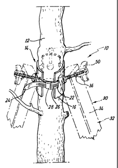
Fig. 1 is a diagrammatic perspective view of part of a first support apparatus
according
to the invention in use;
Figs. 2 and 3 are respectively diagrammatic front and rear perspective views
of part of
the apparatus of Fig. 1;

+ .. , ..r
CA 02343209 2006-05-05
2b
Fig. 4 is a diagrammatic perspective view of a further part of the apparatus
of Fig. l;
Fig. 5 is a diagrammatic perspective view of part of a second apparatus
according to the
invention; and


CA 02343209 2001-03-06
WO 00/13484 PCTlGB99/02928
3
Fig. 6 is a diagrammatic perspective view of part of a third apparatus
according to the invention.
Figs. 1 to 4 show support apparatus 10 suitable for supporting an
upstanding item such as a tree 12. The apparatus 10 comprises a mounting
part 14 in the form of three identical brackets 16. Each bracket 16 comprises
an arcuate section plate 18 from which a threaded projection 20 extends at an
upwards inclination in use. Holes 22 are provided on each side of the
projection 20.
The part 1-i also comprises three ties 2-i for connecting the brackets i6
together in a loop around the tree 12. The ties 2-1 are of the tyke with a
plurality of indents 26 in which a projection (not shown) located in a sleeve
28
automatically locates such that when the ties 2-1 are pulled tight they
automatically lock in position.
The apparatus 10 also comprises a supporting part 30 in the form of
three elongate members 3~?. The members 32 comprise a top bar 3-1 with an
opening 36 adjacent the top end thereof through which a one of the projections
20 can extend in use. The members 32 also comprise a square section tube 38
from which the bar 3-1 telescopically extends. A plurality of spaced holes -10
are
provided towards the lower end of the bar 3-1 and alibnable with a hole -I2
towards the top of the tube 38. A pin -1-1 is mounted near the top of the tube
38
by a cord -I6, and is locatable through the holes -I0, -I2 when aligned to
lock the
bar 3-i in position. A pointed foot -Iii is provided at the lower end of the
tube
30 to be ground engageable.
In use the tree 12 is supported by the three elongate members 32 as
shown, with the projections 20 extending through the openings 36, with the
projections 20 held in position by wing nuts SO threadedly engaging thereon.
The tubes 38 can readily be inserted into the ground at required positions
clear
from the tree 12, and the position of the bars 3~ adjusted telescopically.


CA 02343209 2001-03-06
WO 00/13484 PCT/GB99/02928
4
Fig. 5 shows a further similar apparatus 52. In this instance rather than
providing a projection on the mounting part, this part comprises brackets 54
each with a pair of spaced lugs 56 with holes 58 towards the end thereof. The
elongate members 60 can be mounted on the brackets 54 by hammering nails
through the respective holes 58 to engage thereinto. Alternatively, if a
transverse hole is provided through the top of the members 60 a pin or other
member can be located extending therethrough.
Fig. 6 shows an alternative similar apparatus 7U. In this embodiment
each mounting member comprises a bracket 7-1 which comprises a substantially
square housing 78 with an opening facing the ground. The housing i 8 slides
over the upper end of the elongate member 72. The bracket is further provided
with openings 76 one on each side of the housing 78 to locate the ties or for
straps to extend through to connect the brackets together in a loop around a
tree. The bracket 7-1 and the housing i 8 are integrally formed.
There is thus described support apparatus for trees, other plants or other
upstanding items. The apparatus is of relatively straightfonvard construction
and can thus be inexpensively and robustly manufactured. .~s the elongate
members are inclined relative to the upstanding item it is much easier for
them
to be inserted in the ground. The telescopic nature of the elongate members
allows the mounting part to bf~ provided ar an appropriate place on the
article.
The third apparatus comprising the housing has the advantage that it
covers the bare end of the elongate member and prevents rain from penetrating
the wood. This apparatus is particularly suited for mass production as it
could
be moulded out of the same material.
Various modifications may be made without departing from the scope of
the invention. For example, the mounting brackets may be differently formed
and could be held on the upstanding item other than by the ties. For instance,
straps could be used. The elongate members could be mounted on the brackets
by a different means. The elongate members could comprise more than two


CA 02343209 2001-03-06
WO 00/13484 PCT/GB99/02928
S
components and a different telescopic arrangement may be provided such as
one which provides for infinite adjustment with for instance a locking screw.
A
different number of elongate members could be provided.
Whilst endeavouring in the foregoing specification to draw attention to
those features of the invention believed to be of particular importance it
should
be understood that the Applicant claims protection in respect of any
patentable
feature or combination of features hereinbefore referred to and/or shown in
the
drawings whether or not particular emphasis has been placed thereon.

Representative Drawing
A single figure which represents the drawing illustrating the invention.
Administrative Status

For a clearer understanding of the status of the application/patent presented on this page, the site Disclaimer , as well as the definitions for Patent , Administrative Status , Maintenance Fee  and Payment History  should be consulted.

Administrative Status

Title Date
Forecasted Issue Date 2007-03-13
(86) PCT Filing Date 1999-09-03
(87) PCT Publication Date 2000-03-16
(85) National Entry 2001-03-06
Examination Requested 2003-11-26
(45) Issued 2007-03-13
Deemed Expired 2008-09-03

Abandonment History

There is no abandonment history.

Payment History

Fee Type Anniversary Year Due Date Amount Paid Paid Date
Application Fee $150.00 2001-03-06
Maintenance Fee - Application - New Act 2 2001-09-04 $50.00 2001-03-06
Maintenance Fee - Application - New Act 3 2002-09-03 $50.00 2002-07-23
Maintenance Fee - Application - New Act 4 2003-09-03 $50.00 2003-08-28
Request for Examination $200.00 2003-11-26
Maintenance Fee - Application - New Act 5 2004-09-03 $100.00 2004-07-28
Maintenance Fee - Application - New Act 6 2005-09-05 $100.00 2005-06-06
Maintenance Fee - Application - New Act 7 2006-09-04 $100.00 2006-07-11
Final Fee $150.00 2006-12-12
Owners on Record

Note: Records showing the ownership history in alphabetical order.

Current Owners on Record
STEADMAN, WILLIAM DAVID
Past Owners on Record
None
Past Owners that do not appear in the "Owners on Record" listing will appear in other documentation within the application.
Documents

To view selected files, please enter reCAPTCHA code :


To view images, click a link in the Document Description column. To download the documents, select one or more checkboxes in the first column and then click the "Download Selected in PDF format (Zip Archive)" or the "Download Selected as Single PDF" button.

List of published and non-published patent-specific documents on the CPD .

If you have any difficulty accessing content, you can call the Client Service Centre at 1-866-997-1936 or send them an e-mail at CIPO Client Service Centre.


Document
Description 
Date
(yyyy-mm-dd) 
Number of pages   Size of Image (KB) 
Representative Drawing 2001-05-29 1 8
Abstract 2001-03-06 1 49
Description 2001-03-06 5 195
Claims 2001-03-06 3 141
Drawings 2001-03-06 3 58
Cover Page 2001-05-29 1 25
Description 2006-05-05 7 250
Claims 2006-05-05 4 125
Representative Drawing 2007-02-13 1 10
Cover Page 2007-02-13 1 35
Assignment 2001-03-06 3 119
PCT 2001-03-06 15 524
Fees 2003-08-28 1 39
Prosecution-Amendment 2003-11-26 1 34
Fees 2002-07-23 1 44
Fees 2004-07-28 1 36
Fees 2005-06-06 1 39
Prosecution-Amendment 2005-11-07 2 69
Prosecution-Amendment 2006-05-05 11 337
Fees 2006-07-11 1 46
Correspondence 2006-12-12 1 42