Note: Descriptions are shown in the official language in which they were submitted.
CA 02343215 2001-03-08
M,
Method and device for regenerating an electroless metal
deposition bath by electrodialysis
Specification:
The invention relates to a method and a device for
regenerating by electrodialysis an electroless metal
deposition bath, especially an electroless nickel
deposition bath.
The electroless metal-plating of workpieces has been
known for a long time. For exarnple, sanitary fittings
made of plastics material are provided with metal
layers in order to obtain a specific aesthetic
appearance, or specific workpieces consisting of metal,
in order to improve their serviceability, for example
the wear-resistance or corrosiorl behaviour. Thus, in
machine-building, parts which are mechanically heavily
loaded receive resistant coatinqs comprising a largely
amorphous nickel/phosphorus alloy layer in order to
increase the resistance to abrasion, for example of
bearing shells on moveable parts. In oil production,
metal parts used in the off-shore domain are coated
with a nickel/phosphorus layer of: this type in order to
improve the material resistance to chemical influences.
Electroless plating with metals is based on an
autocatalytic process in which dissolved metal ions are
reduced to metal by means of a reducing agent located
in the deposition solution, and deposited on the
workpiece to be coated. In this case, additional
components are often incorporated. into the metal layer,
for example phosphorus. As well as nickel, copper can
also be deposited by this method.
CA 02343215 2001-03-08
2
For the deposition of nic:kel/phosphorus layers,
electrolytic and electroless methods can basically be
used. Electrolytic methods are admittedly easier to
handle; however they have the disadvantage that layers
of uniform thickness can only be obtained if the parts
to be coated have a simple geometry. The electrolytic
metallisation of workpieces vvhich have a complex
geometry, for example curvatures, holes or undercuts,
leads to an uneven layer thickness and thus in many
cases to intolerable local fluctuations in the plating
result. Moreover, the metal layers deposited in an
electroless manner often have more advantageous
mechanical properties than metal layers deposited by
electrolytic means. For this reason, electroless
methods are very frequently used for plating.
Electroless metal deposition is, represented below in
the example of electroless nickel deposition with
simultaneous incorporation of phosphorus into the
layer. In this process, a deposition solution is used,
for example, which contains sodium hypophosphite as the
reducing agent for nickel ions, as well as nickel ions,
for example as nickel sulphate. The deposition
reaction takes place accordiizg to the following
reaction equation:
Ni S04 + 6 NaH2PO2 Ni + 2 H2 + 2 P+ 4 NaH2PO3 + Na2SO4
Thus in this reaction, dissolved nickel and
hypophosphite ions are constantly consumed, whilst the
concentration of orthophosphite (H3PO3-) increases as an
oxidation product. Moreover the counterions of the
nickel cations and hypophosphite anions accumulate in
the form of Na2SO4.
CA 02343215 2001-03-08
3
Thus, methods of this type have the disadvantage that
the process management is complicated in many cases and
a large number of monitoring operations has to be
carried out in order to achieve constant deposition
conditions. In addition to this, the service life of
the electroless deposition baths is limited. In metal
deposition, the reducing agent and the metal ions are
used up which have to be continually added as the
method is carried out, in order to make available an
approximately constant content of available reducing
agent and available metal ions within a narrow band
width. Since the reducing agent and the salts
containing the metal ions leave behind, during the
deposition reaction, products which accumulate in the
deposition bath, the service life of the bath is
inevitably limited. For example, the metal ions are
added to the bath in the form of salts, such that
disturbing anions, such as sulphate ions accumulate in
the bath. The same is true for orthophosphite ions
(H2P03-) which form in the bath through oxidation of
hypophosphite ions.
The age of a bath is generally quoted in metal turnover
(MTO). 1 MTO corresponds to the amount of deposited
metal from the bath which corresponds to the initially
used concentration of the metal ions in the bath,
respectively in relation to the total volume of the
bath. Generally, the degradation products in the bath
reach such a high concentration after 6 to 10 MTO that
the quality and deposition speed of the metal are no
longer within tolerable ranges. Therefore baths of
such an age are not used again. A new bath must be
started and the spent one must be thrown away. what is
disadvantageous is that the necessary disposal of the
baths and the required new charging of fresh baths lead
to high costs and considera.ble damage to the
CA 02343215 2001-07-19
4
environmen.t. For this reason, different methods have been
proposed by means of which the service life of baths of this
type can be extended.
In US-A-5,221, 328, a method for extending the service life
of electroless nickel baths is described, by means of which
method orthophosphite which has been produced in a
nickel/phosphorus deposition bath can be precipitated as a
metal salt and separated. Yttrium and lanthanides can be
considered as precipitants. However, the necessary
chemicals for thi:; are extremely expensive. Moreover, the
dissolved componerits of these additives, remaining in the
bath, can impair the quality of the metal coatings.
In "Plating arid Surface Finishing", September 1995, pages 77
to 82, it is proposed by C.D. Iacovangelo that the
disturbing precipit:.ation of nickel orthophoshite be
prevented through t:.he addition ofcomplexing agents. By
this means, the concentration of dissolved free nickel ions
is reduced.
In the ENVIRO CP-process* of the company Marietta, U.S.A.,
the disturbing components in the bath are separated by means
of adsorption on ion-exchange resins. For the complete
separatiori and regeneration of the deposition bath, a
complex process is carried out in which a plurality of
different ion-exchange columns and containers for diverse
process liquids are needed.
Y. Kuboi and R. Takeshita describe a method of separating
the undesired bath ccmponents by electrodialysis
(Electroless Nickel Conference 1989, Proceedings, Prod.
Finishing Magazine, 1989, pages 16-1 to 16-15). In this
method, ttie electroless nickel bath
* Trade-mark
CA 02343215 2006-06-22
is led as so-called diluate through an electrodialysis cell.
The diluate compartment in the electrodialysis cell is, for
this purpose, separated on the anode side by an anion-exchange
membrane from the anode compartment which is in contact with
5 the anode, and on the cathode side by a cation-exchange
membrane from the cathode compartment which is in contact with
the cathode. These two last-mentioned compartments are also
referred to as concentrate compartments. The undesired
sulphate and orthophosphite ions in the deposition bath are
transported into the anode compartment and the undesired
sodium ions, which come from the sodium hypophosphite used,
are transferred into the cathode compartment. In laboratory
tests, however, it has emerged that, in addition to the
undesired sulphate, orthophosphite and sodium ions, the bath
constituents important for the deposition process, namely the
nickel and hypophosphite ions and the organic complexing
agents (mostly carboxylic acids or anions thereof), are
transported into the concentrate compartments.
In German Patent No. DE 43 10 366 Cl, published October 13,
1994, a method of regenerating electroless nickel/phosphorus
baths by electrodialysis is described. The nickel/phosphorus
bath to be regenerated is to this end led through a
compartment in an electrodialysis cell which is separated
from the adjacent compartments both on the cathode side and
on the anode side by respectively one anion-exchange
membrane (diluate compartment). Through the application of
an electrical field, ortho- and hypophosphite ions are
transferred into the concentrate compartment lying on the
anode side of the diluate compartment. This solution is then
transported into the cathode compartment which is in contact
with the cathode. Hypophosphite can by transference pass from
_. -_.:..,.......__ .....:....... _ . .... .._:. ...... . . .. .... . ..
...... ... ._ ._.__.. ._... . .. .. _.. . _ _._....... . . . . _. .. ... ....
. . . . _ .. . . _ . . . .
CA 02343215 2001-03-08
6
there into the diluate compartment again, whilst
orthophosphite is reduced to hypophosphite at the
cathode and the hypophosphite produced is then also to
be transferred into the diluate compartment. However,
it has emerged in tests that this reduction reaction
does not in fact take place. Furthermore the parallel
connection of a large number of the quoted cells is
proposed. Even with this cell, the disadvantage is not
overcome which is inherent in the method described by
Y. Kuboi and R. Takeshita. Nioreover, sulphate and
sodium ions also accumulate in this solution.
In US-A-5,419,821, too, an electrodialytic method of
regenerating electroless metaLllisation baths is
described. In a similar manner to DE 43 10 366 Cl,
hypophosphite and orthophosphite are transferred via an
anion-exchange membrane into a c:oncentrate compartment
on the anode side and thus separated. In this case,
too, the concentrate solution on the anode side is
transferred into the cathode compartment, such that
hypophosphite can from there reach the diluate
compartment again. Orthophosphite is precipitated
through the addition of magnesium or calcium salts to
the solution which flows through this compartment, and
in this way removed from the overall process. What is
disadvantageous, however, is that. disturbing sodium and
sulphate ions cannot be removed from the nickel bath
solution.
In order to overcome the disadvantages of the methods
described above, a method for the electrodialytic
regeneration of electroless nicke:l/phosphorus baths was
proposed in EP 0 787 829 Al, in which the method is
used in two different variants. In each of the
variants, this method is operated discontinuously. The
one variant represents a two-staqe method in which the
.._.. _._.,.: . .:.:::........._. ...... . ._...... .. _ . . . .. . . . .. . .
. ii'
CA 02343215 2001-03-08
7
spent deposition solution is first led into the diluate
compartment of an electrodialysis cell, which is
delimited from two concentrate compartments by an
anion-exchange membrane on the side facing the anode
and by a monoselective cation-exc:hange membrane on the
side facing the cathode. Monoselective ion-exchange
membranes dif f er from normal ion-exchange membranes in
that they do not allow singly charged ions to pass, nor
even ions which are multiply charged. In the first
stage of the method, sociium, hypophosphite,
orthophosphite, sulphate and carboxylic acid ions are
transferred to the adjacent compartments, whilst nickel
ions remain in the diluate cornpartment. Then the
respective solutions are led into a second
electrodialysis cell in which the concentrate
compartment is disposed between two diluate
compartments and separated from the latter on the anode
side by a monoselective anion-exchange membrane and on
the cathode side by a cation-ex.change membrane. In
this case, the hypophosphite and carboxylic acid anions
and the sodium cations are transferred into the diluate
compartment again, but not the orthophosphite and
sulphate ions. From the balance, therefore, the
orthophosphite and sulphate ions are removed but not
the sodium ions. Since the charge balance is
guaranteed in each individual method step, the total
amount of the orthophosphite and sulphate ions cannot
be removed since the proportion of anionic counterions
corresponding to the sodium ions remaining in the
diluate compartment must also remain in the diluate
compartment. Thus the efficacy of the separation is
considerably impaired.
In the second variant, which is designed as a single-
stage method, the bath solution is placed in the
cathode compartment of an electrodialysis cell
CA 02343215 2006-06-22
8
comprising three electrolyte compartments, the central
compartment being separated from the other compartments on the
anode side by a monoselective anion-exchange membrane and on
the cathode side by a monoselective cation-exchange membrane.
The solution contained in the anode compartment is led into
the cathode compartment. The bath solution is first led into
the cathode compartment. Hypophosphite and orthophosphite ions
are supposed to be transferred into the central compartment.
However, this appears impossible since a cation-exchange
membrane is disposed between the two compartments. For this
reason, it is not clear how the method can be realised.
The main problem of the known devices and methods accordingly
consists in guaranteeing as effective and complete removal as
possible of disturbing ions from the nickel/phosphorus
deposition solution. These substances are in particular
sodium, orthophosphite and sulphate ions. Moreover the method
should be able to be carried out as continuously as possible
during the operation of the bath and only require one method
step, in order to minimise the outlay. The problem underlying
the present invention is, therefore, to avoid these
disadvantages.
In another aspect, the present invention provides a method for
regenerating by electrodialysis an electroless metal
deposition bath, containing hypophosphite ions as a reducing
agent, in which the liquid of the bath is led through diluate
compartments in a first electrodialysis unit having at least
one cathode and at least one anode, which compartments are
separated from concentrate compartments in the electrodialysis
unit on the cathode side by monoselective cation-exchange
membranes and on the anode side by anion-exchange membranes,
the diluate compartments and the concentrate compartments
being disposed alternately to one another, characterized in
CA 02343215 2006-06-22
8a
that the bath solution is led simultaneously through diluate
compartments in a second electrodialysis unit having at least
one cathode and at least one anode, which compartments are
separated from concentrate compartments in the second
electrodialysis unit on the cathode side by monoselective
anion-exchange membranes and on the anode side by
anion-exchange membranes, the diluate compartments and the
concentrate compartments in the second electrodialysis unit
being disposed alternately to one another.
In another aspect, the present invention provides a device for
regenerating by electrodialysis an electroless metal
deposition bath containing hypophosphite ions as a reducing
agent, the device containing (a) a first electrodialysis unit
containing two concentrate compartments and a diluate
compartment, disposed between same, as electrolyte
compartments, the diluate compartment being separated on the
cathode side from the one concentrate compartment by a
monoselective cation-exchange membrane and being separated on
the anode side from the other concentrate compartment by an
anion-exchange membrane, (b) in the first electrodialysis unit
at least one cathode and at least one anode and (c) a power
supply for the cathodes and the anodes, characterised by (d) a
second electrodialysis unit containing two diluate
compartments and a concentrate compartment, disposed between
same, as electrolyte compartments, the concentrate compartment
being separated on the cathode side from the one diluate
compartment by an anion-exchange membrane and being separated
on the anode side from the other diluate compartment by a
mononselective anion-exchange membrane, as well as at least
one cathode and at least one anode and a power supply for
cathodes and the anodes.
CA 02343215 2006-06-22
8b
Accordingly, the invention relates to a method and a
device for regenerating by electrodialysis electroless
metal deposition baths containing hypophosphite ions as
the reducing agent, especially baths for depositing
nickel/phosphorus layers, and proceeds from the fact
CA 02343215 2001-03-08
9
that the bath solution is led through diluate
compartments in a first electrodialysis unit having
cathodes and anodes, which compartments are separated
from concentrate compartments in the electrodialysis
unit on the cathode side by monoselective cation-
exchange membranes and on the anode side by anion-
exchange membranes. The bath solution is also led
simultaneously through diluate cornpartments in a second
electrodialysis unit, connected hydraulically in
parallel to the first unit and having cathodes and
anodes, which compartments are separated from
concentrate compartments in the second electrodialysis
unit on the cathode side by monoselective anion-
exchange membranes and on the anode side by anion-
exchange membranes. In both the electrodialysis units,
the diluate compartments and the concentrate
compartments are disposed respectively alternately to
one another.
In the simplest embodiment of the invention, the device
has the following equipment features:
a. a first electrodialysis unit, containing two
concentrate compartments and a diluate compartment
disposed between same as electrolyte compartments,
the diluate compartment being separated on the
cathode side from the one concentrate compartment
by a monoselective cation-exchange membrane and on
the anode side from the; other concentrate
compartment by an anion-excharige membrane,
b. a second electrodialysis unit, containing two
diluate compartments and a concentrate compartment
disposed between same as electrolyte compartments,
the concentrate compartment being separated on the
cathode side from the one diluate compartment by an
anion-exchange membrane and on the anode side from
CA 02343215 2001-03-08
the other diluate compartment by a monoselective
anion-exchange membrane, furthermore
c. in each electrodialysis unit at least one
cathode and at least one anode and
5 d. a power supply for the cathodes and the
anodes.
The spent bath solution, which as well as the valuable
substances in the bath, i.e. hypophosphite, carboxylic
10 acid and nickel ions, also contains disturbing
accompanying substances, narnely, for example,
orthophosphite, sulphate and sodium ions, is led
simultaneously into all the diluate compartments of the
two electrodialysis units. Through transference, in
the first electrodialysis unit all the anions are
transferred from the diluate compartment into the
concentrate compartments disposed on the anode side of
same, and the sodium ions into the concentrate
compartments disposed on the cathode side of same,
whilst nickel ions remain in the diluate compartment.
In the second electrodialysis unlt, only the monovalent
anions, namely hypophosphite and carboxylic acid ions,
are transferred from the concentrate compartments into
the diluate compartments on the anode side, whilst in
this case the cations contained in the concentrate
compartment and the divalent anions, namely
orthophosphite and sulphate ions, remain in this
compartment.
Since in the first electrodialysis unit a monoselective
cation-exchange membrane is used in the diluate
compartment on the cathode side, sodium ions are
transferred selectively from the diluate compartment
into the concentrate compartment. Nickel ions cannot
escape from the diluate compartment because of the
special arrangement of the membranes. Moreover,
CA 02343215 2001-03-08
.. t
11
through an anion-exchange membrane being used in both
electrodialysis units in the diluate compartment on the
anode side, hypophosphite is admittedly transferred
from the diluate compartment into the concentrate
compartment, but also orthophosphite and sulphate. The
loss of hypophosphite and carboxylic acid ions from the
diluate compartment is selectively compensated for
again, by a monoselective anion-exchange membrane being
disposed in the second electrodialysis unit in the
concentrate compartment on the anode side, such that
these ions are selectively transferred from the
concentrate compartment to the diluate compartment.
Thus, in the balance, during cor.Ltinuous circulation of
the solution through the two electrodialysis units,
only the sodium, orthophosphite and sulphate ions are
removed from the spent solution, whilst the valuable
substances remain in the solution. With the method
according to the invention and the device, the optimal
efficiency of the separation of disturbing bath
constituents and thus the solution of the problem
underlying the invention is consequently achieved.
By both electrodialysis units being operated
hydraulically in parallel and not in a sequential
method, electroneutrality must be guaranteed in respect
of the ion transport only within the total arrangement.
This means that only in respect of the total
arrangement must the amount of anionic substances,
which pass the membranes in the anodic direction, be
equal to the amount of cationic substances which pass
the membranes in the cathodic direction. The bath
solution circulates continuously again and again
through both electrodialysis units, such that the
disturbing substances, which are at first only
partially separated, are qradually completely
CA 02343215 2001-03-08
12
separated. For this reason, disadvantageous effects
such as those connected with the two-stage method of EP
0 787 829 Al are not observed.
In order to achieve, in particular, continuous
operation of the electrodialytic method, a concentrate
solution is led simultaneously through the concentrate
compartments. This concentrate solution contains the
disturbing substances removed substantially through
enrichment from the spent bath solution. So that the
concentration of these disturbinq substances does not
rise above a critical value, the concentrate solution
is diluted continuously or at least from time to time
(intermittently). Moreover, sodium hydroxide can be
added to this solution. This addition renders possible
an effective separation of the orthophosphite ions from
the hypophosphite ions, by an optimal pH value of the
concentrate solution being set above roughly 8.5
( f orming HP032 - f rom H2P03 -).
What is guaranteed in this way is that the disturbing
bath constituents can be continuously removed from the
spent solution. Otherwise, these substances would
accumulate in the concentrate solution above a critical
value and lead to a reduction in the separation effect,
since the disturbing substances could in these
circumstances only be inadequately transferred into the
concentrate solution.
In order to exploit the advantages of the
electrodialytic method, preferably in the first
electrodialysis unit respectively at least two diluate
compartments and at least three concentrate
compartments are disposed alternately to one another,
and in the second electrodialysis unit respectively at
least two concentrate compartments and at least three
CA 02343215 2001-03-08
13
diluate compartments. In this way, with predetermined
dimensions of the ion-exchange membranes, a
sufficiently large exchange area for the spent bath
solution is made available in the membranes. The
larger this exchange surface is, the faster and more
effectively the regeneration of the bath can progress
also. Therefore, in an optimal configuration for the
regeneration arrangement, a large number of diluate
compartments and concentrate compartments in the first
electrodialysis unit and a lar=ge number of diluate
compartments and concentrate compartments in the second
electrodialysis unit are disposed in respectively
alternating sequences to one another. In this way, two
stacks of electrolytic cells are created through which
the diluate solution is led through the diluate
compartments and the concentrate solution through the
concentrate compartments. Basically, the two
electrodialysis stacks do not have to have the same
number of electrolyte compartments. For example, it
can be advantageous to provide a larger number of
diluate compartments and concentrate compartments in
the first electrodialysis unit than in the second
electrodialysis unit.
The special arrangement of the ion-exchange membranes
results in the concentrate compartments in the first
electrodialysis unit being delimited on the cathode
side by anion-exchange membranes and on the anode side
by monoselective cation-exchange membranes. The anode
and the cathode are disposed on the end faces of the
electrodialysis stack. The electrolyte compartments in
contact with the cathode and the anode are, differently
from the given sequence of membranes which separate the
respective compartments from one another, are separated
from the adjacent electrolyte compartments by cation-
exchange membranes. In these outer electrolyte
CA 02343215 2001-03-08
14
compartments is to be found an electrochemically inert
conducting salt solution, for example a sodium sulphate
solution. This guarantees that no undesired electrode
reactions take place in these compartments, which would
lead to destruction of the electrodes or to the
formation of undesired reaction products on the
electrodes.
In the same manner, the concentrate compartments in the
second electrodialysis unit are delimited on the
cathode side by anion-exchange membranes and on the
anode side by monoselective anion-exchange membranes.
In this case too, an anode or respectively a cathode is
disposed on the end faces; of this second
electrodialysis stack. The electrolyte compartments in
contact with the cathode and the anode, differently
from the given sequence of membranes which demarcate
the diluate and concentrate compartments from one
another, are separated from the adjacent electrolyte
compartments by cation-exchange membranes. In this
second case, too, correspondingly inert solutions are
to be found in the cathode compartment and the anode
compartment, such that no undesired electrode reactions
can take place.
The surface ratio of the normal anion-exchange
membranes to the monoselective anion-exchange membranes
in both electrodialysis stacks and the pH value of the
solution led through the concentrate compartments
(preferably at least 8.5) determine the degree of loss
of anionic valuable substances, i.e. of hypophosphite
and carboxylic acid anions.
In a preferred embodiment, the first electrodialysis
unit and the second electrodialysis unit are combined
in a common electrodialysis stack and disposed in such
CA 02343215 2001-03-08
a manner that a cathode is disposed on only one end
face of the common electrodialysis stack, and an anode
on the other. To this end, the respective stacks are
not electrically insulated from one another. Rather,
5 for this purpose, an anion-exchange membrane is
arranged on the boundary surfaces between the stacks to
delimit the end concentrate compartment on the cathode
side of the first electrodialysis unit from the end
diluate compartment on the anode side of the second
10 electrodialysis unit. In this case, the corresponding
cathode compartment provided on the end electrolyte
compartments is dispensed with, as are the
corresponding anode compartrnent and the associated
electrodes. In this case, therefore, only one cathode
15 compartment and one anode compa:rtment are provided on
the end faces of the stack, as well as one cathode and
one anode there.
In a further preferred alternative embodiment of the
invention, the first electrodialysis unit and the
second electrodialysis unit are again combined in a
common electrodialysis stack; in this case, however,
the sequence of the individual electrolyte compartments
is so selected that the electrolyte compartments of the
one electrodialysis unit, which are aligned towards the
cathode, are aligned towards the respectively other
electrodialysis stack. Between the two electrodialysis
units are disposed a common cathode, and respectively
one anode on the two end faces of the common
electrodialysis stack. This combination has the
advantage that only one stack has to be manufactured.
In this case, two power supplies are provided, namely a
power supply for the cathode and the one anode and a
further power supply for the cathode and the other
anode. The electric circuits of the two
electrodialysis units can, of course, also be connected
CA 02343215 2001-03-08
16
in parallel, such that again one power supply is
sufficient.
In an alternative embodiment to the above, the reverse
sequence of the individual electrolyte compartments is
chosen. In this case, the electrolyte compartments of
the one electrodialysis unit, which are aligned towards
the anode, are aligned towards the respectively other
stack of electrolytic cells. Between the two
electrodialysis units is disposed a common anode and on
the two end faces of the common electrodialysis stack
respectively one cathode.
In a further preferred embodiment according to the
invention, the bath solution of the deposition bath is
led in a first circuit via a diluate container. For
this purpose, solution guiding means (pipelines, hoses)
are provided between the container in which the
deposition bath is located and the diluate container.
For example, the deposition solution is circulated by
suitable pumps continuously from the bath container
into the diluate container, and from there back into
the bath container. The solution contained in the
diluate container is led in a second circuit through
the diluate compartments in the first and the second
electrodialysis unit, and from there back again. The
solution is therefore transported via the diluate
container into the diluate compartments of the
electrodialysis units and not directly from the bath
container into the electrodialysis units. By this
means, greater flexibility of the plant is achieved,
since the volume flow (circulating volume of liquid per
time unit) can be adjusted in the two circuits
independently of one another.
CA 02343215 2001-03-08
17
In a particularly preferred embodiment, the volume flow
in the second circuit is set higher than the volume
flow in the first circuit by at least one order of
magnitude. The volume flow in the first circuit is
preferably even at the most 1% of the volume flow in
the second circuit. What is thereby achieved is that
only a small volume flow of the bath solution which is
regularly heated up to a high temperature has to be
cooled, so that the heat-sensitive ion-exchange
membranes and installation parts in the electrodialysis
units are not destroyed, and subsequently heated up
again. In this way, low heat losses are achieved such
that a heat exchanger can possibly be dispensed with.
For continuous removal of disturbing substances from
the deposition solution, a relatively large liquid
volume flow is continually led through the diluate
compartments. The liquid is cooled during transfer
into the diluate container. Special heat-exchangers
are not required for this. Since only a small volume
flow is conveyed into the diluate container, only a
little heat has to be taken from the bath solution and
added again during the return. Thus, the heat loss is
low.
The diluate container can, moreover, be used to track
the bath components used up during the metal
deposition, namely nickel and hypophosphite ions.
Through metering corresponding substances, for example,
nickel sulphate and sodium hypophosphite, into the
diluate container, these substances can be completely
mixed with the deposition solut:ion flowing through,
before the solution enriched with these substances
enters the bath container again. If these substances
are added directly to the bath container, there is the
danger that nickel is deposited in metallic form on
container fittings or walls, since with the addition of
CA 02343215 2001-03-08
18
the salts, locally increased concentrations of these
substances are formed.
In addition, a concentrate container can be provided
from which the concentrate solution is led into the
concentrate compartments in the electrodialysis stack
and from there back again to the concentrate container.
In order to maintain a suitablEa concentration of the
constituents of the concentrat.e solution, there is
preferably disposed in the concentrate container a
water supply, with which dilution of. the solution is
possible. Through the passage of the disturbing
substances out of the diluate into the concentrate,
these substances accumulate continuously in the
concentrate, such that dilution becomes necessary. The
supply of water is controlled, for example, by the
electrical conductivity of the concentrate solution.
The NaOH solution is also metered into this container.
The monoselective ion-exchange membranes mentioned here
are those ion-exchange membranes which only allow ions
with a single charge to pass, monoselective cation-
exchange membranes, i.e. sodium and hydronium (H30*)
ions, and monoselective anion-exchange membranes, for
example hypophosphite, hydroxide and carboxylic acid
anions, whilst these membranes are substantially
impermeable to multiply charged ions, i.e. nickel,
sulphate and orthophosphite ions. If reference is only
made to anion- or cation-exchange membranes, without
referring to monoselective properties, these are those
ion-exchange membranes which have no selectivity in
respect of the number of charges of the ions passing.
The invention is explained in greater detail below with
the aid of figures. These show in detail:
CA 02343215 2001-03-08
19
Fig. 1: a schematic representation of
the partial processes in the first and
in the second electrodialysis unit;
Fig. 2: a schematic representation of
a first embodirnent of the device
according to the invention;
Fig. 3: a schematic representation of
a second embodiment of the device
according to the invention.
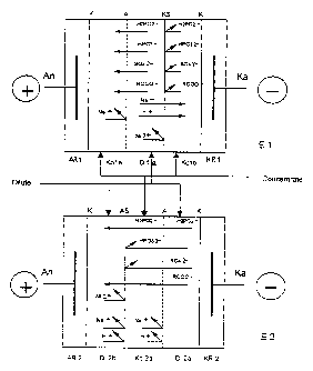
In Fig. 1, the basic structure of the electrodialysis
units in the simplest embodiment is represented
schematically. In both cases, anodes An and cathodes
Ka are contained in the corresponding anode
compartments AR1, AR2 or respectively the corresponding
cathode compartments KR1, KR2. In these compartments
is located exchangeable electrolyte solution,
preferably a sodium sulphate solution.
The anode or cathode compartments are separated from
the adjacent electrolyte compartments by cation-
exchange membranes K. Membranes of this type, just as
the remaining ion-exchange membranes used, are freely
available, for example from the company DuPont de
Nemours, U.S.A.
The diluate solution flows through all the diluate
compartments Di and the concentrate solution through
all the concentrate compartments Ko. This is indicated
schematically by the arrows.
In the electrodialysis unit El, which is represented
schematically in the upper portion of Fig. 1, a first
concentrate compartment Kola communicates with the
anode compartment AR1. The two compartments are
CA 02343215 2006-06-22
separated from one another by a cation-exchange membrane K.
Through the concentrate compartment Kola flows the concentrate
solution, preferably a slightly alkaline solution which,
during operation, contains the substances which are taken up
5 from the diluate solution (for example orthophosphite,
sulphate, or sodium ions) . This first concentrate compartment
is delimited on the cathode side by an anion-exchange membrane
A. Towards the cathode, the concentrate compartment Kola
communicates with a diluate compartment Dila, through which
10 the diluate solution flows. On the cathode side, a
concentrate compartment Kolb, through which the concentrate
solution flows, communicates in turn with the diluate
compartment. Compartments Dila and Kolb are separated from one
another by a monoselective cation-exchange membrane KS. The
15 concentrate compartment Kolb is divided from the adjacent
cathode compartment KR1 by a cation-exchange membrane K.
Sodium ions contained in the concentrate compartment Kola
are not transferred into the diluate compartment Dila. In
20 the diluate solution are found, in the case of a typical
nickel/phosphorus deposition bath, nickel, sodium,
hypophosphite (H2PO2-), orthophosphate (HP032-), sulphate and
carboxylic acid (RCOO-) ions. Of the types of ions located
in the diluate compartment Dila, all the anions, i.e.
hypophosphite, orthophosphite, sulphate and carboxylic
acid anions are transferred through the anion-exchange
membrane A in to the concentrate compartment Kola, and of
the cations, the singly charged sodium and hydronium ions
are transferred through the monoselective cation-exchange
membrane KS into the concentrate compartment Kolb. On the
other hand the double-charged nickel ions are not
transferred into the concentrate compartment Kolb but
CA 02343215 2001-03-08
21
remain in the diluate compartrnent. Hydroxide ions,
possibly contained in the concentrate compartment Ko1b
in a low concentration, cannot pass into the diluate
compartment. The same is also true for the
hypophosphite, orthophosphite, sulphate and carboxylic
acid ions.
In the overall balance of the electrodialysis unit El,
therefore, all the anions are transferred into the
concentrate compartment, whilst of the cations only the
sodium ions and the hydronium ions, pass into the
concentrate compartment, but not the nickel ions.
in the electrodialysis unit E2, which is represented
schematically in the lower portion of Fig. 1, a first
diluate compartment Di2b commur.iicates with the anode
compartment AR2. The anode compartment is delimited on
the cathode side by a cation-exchange membrane K. The
diluate solution flows through this diluate
compartment. The diluate compartment is delimited on
the cathode side by a monoselective anion-exchange
membrane AS. On the cathode side, there adjoins a
concentrate compartment Ko2a, through which the
concentrate solution flows. This compartment is
divided by an anion-exchange membrane A from an
adjacent second diluate compartment Di2a, through which
the diluate solution flows. This second diluate
compartment Di2a is divided on the cathode side from
the adjoining cathode compartment KR2 by means of a
cation-exchange membrane K.
Cations cannot pass from the first diluate compartment
Di2b into the adjoining concentrate compartment Ko2a,
since the two compartments are separated from one
another by a monoselective anion-exchange membrane AS.
CA 02343215 2001-03-08
22
Equally, sodium ions contained in the concentrate
compartment cannot pass into the second diluate
compartment Di2a, since in this case the transfer of
sodium ions is opposed by an anion-exchange membrane.
Anions contained in the second diluate compartment
Di2a, namely hypophosphite, ort.hophosphite, sulphate,
carboxylic acid and hydroxide ions, are transferred
into the central concentrate compartment Ko2a. Of the
anions which have reached the concentrate compartment,
only the singly charged anions can pass through the
monoselective anion-exchange membrane AS into the
diluate compartment Di2b, namely hypophosphite,
carboxylic acid and hydroxide ions.
In the overall balance of the partial processes running
in this electrodialysis unit, the disturbing bath
constituents are thus selectively transferred into the
concentrate compartment, whilst t:he valuable substances
are returned again to the diluate solution after
passing the concentrate compartment.
The electrodialysis unit according to the invention
comprises two electrodialysis stacks El and E2, as
shown in Fig. 2. These are shown in the detail in the
lower portion of Fig. 2, separately enlarged as a basic
unit. The two stacks are combined into a common stack.
The electrodes are attached to the end faces of the
common stack, in Fig. 2 on the left-hand side an anode
An and on the right-hand side the cathode Ka. As the
anode is used, for example, a stainless steel plate or
titanium coated with noble metal mixed oxides or
platinum-plated. A plate of the same material can be
used for the cathode. The individual electrodialysis
cells within the stack comprise respectively specially
shaped frames which leave the diluate compartments Di
or concentrate compartments Ko free and have ducts in
CA 02343215 2001-03-08
23
order to permit a guided flow of the diluate solution,
on the one hand, and of the concentrate solution on the
other hand, through the individual compartments. The
ducts are here so formed that the liquid coming from
the diluate container VD can enter simultaneously all
the diluate compartments Di. and =the liquid coming from
the concentrate container VK car.L enter simultaneously
all the concentrate compartments Ko.
Furthermore, seals are contained in the stack in order
to prevent any escape of liquid from the stack or
passing of liquid from one compartment to an adjacent
compartment. On the end surfaces are provided force-
absorbing plates, made of steel for example. The whole
stack is screwed by means of bolts, which extend
through the entire stack, or tens_Loned hydraulically.
The whole stack has, moreover, the ion-exchange
membranes which are required for separating the types
of ion and which separate the individual compartments
from one another. The electrodialysis unit El
comprises diluate compartments lDi1a, Dilb, Dilc, .,
Dilx, and concentrate compartments Kola, Koib, Ko1c,
..., Koix, disposed alternating with one another.
Towards the cathode side, the di=Luate compartments are
separated from the concentrate compartments by
monoselective cation-exchange membranes KS and towards
the anode side by anion-exchange membranes A. The
anode An is in direct contact with the outer
compartment of the electrodialysis unit El on the anode
side. This is the anode compartment here. The anode
compartment is separated from the adjacent concentrate
compartment Kola by a cation-excY:Lange membrane K.
CA 02343215 2001-03-08
24
At the outer concentrate compartment Kolx on the
cathode side, electrodialysis unit El is connected
with electrodialysis unit E2. T:he connection point is
provided by an anion-exchange membrane A. On the
cathode side is located, adjacent to this anion-
exchange membrane, a diluate contpartment Di2x of unit
E2. In this electrodialysis unit E2, the diluate
compartments Di2x, ..., Di2c, Di2b, Di2a and the
concentrate compartments Ko2x, ..., Ko2c, Ko2b, Ko2a
alternate with one another. For example, two diluate
compartments Da.i and three co:ncentrate compartments
Kol can be combined in electrodialysis unit El and
three diluate compartments Di2 and two concentrate
compartments Ko2 can be combined in electrodialysis
unit E2.
Each diluate compartment Di2 is. separated from the
adjacent concentrate compartmen-ts Ko2 by an anion-
exchange membrane A towards the anode side and by a
monoselective anion-exchange membrane AS towards the
cathode side.
The cathode Ka is in direct contact with the outer
compartment on the cathode side of electrodialysis unit
E2. This is the cathode compartment. The cathode
compartment is separated from the adjacent diluate
compartment Di2a by a cation-exchange membrane.
The anode An and the cathode Ka are connected with a
rectifying power supply S.
The bath solution is pumped, coming from the bath
container B, via a pipeline R1, into the diluate
container VD, for example with a volume flow of 20 1/h.
The solution in the container VD is led via a further
CA 02343215 2001-03-08
pipeline R2 back into the container B. In the diluate
container VD, the nickel/phosphorus deposition solution,
entering at a temperature of, for example, 90 C, cools
down to a temperature of 40 C, for example.
5
From the diluate container, the deposition solution is
conveyed by means of a pump PD via a pipeline R3 into
all the diluate compartments Di1 and Di2 of the
electrodialysis units El and E2. The volume flow is
10 for example 7 m3/h. After the solution has passed
through the diluate compartments, it returns via
pipeline R4 to the diluate container.
A concentrate solution flows through the concentrate
15 compartments Kol and Ro2 of the two electrodialysis
units. The concentrate solution is located in the
concentrate container VR. The solution is conveyed by
means of a pump PR via pipeline R5 simultaneously into
all the concentrate compartments. After the solution
20 has passed through these compartments, it returns to
the concentrate container via pipeline R6. Since the
disturbing substances located in the deposition
solution, such as orthophosphite, sulphate and sodium
ions, constantly accumulate in the concentrate
25 solution, the latter must be continuously diluted in
order to prevent any inhibition of the transfer of
these types of ion through the ion-exchange membranes.
To this end, water is added to the concentrate
container continuously or intermittently.
In order, furthermore, to set ar.L optimal pH value for
the selective transfer of orthophosphite ions in the
concentrate solution, the pH value of the concentrate
solution is set at values above 8.5 by adding sodium
hydroxide to the solution. This hydroxide must be
continuously added since hydroxide ions are used up by
~ __ _ ----- ,-~-;,, -,-----
CA 02343215 2001-03-08
26
conversion of HP032' into H2PO3' and are thus lost from
the concentrate solution.
In a further embodiment (Fig. 3) the electrodialysis
units El and E2, shown as per Fig. 2, are used. The
two units are also combined in a common stack, however
in the manner that the cathode sides of the two units
adjoin one another and a cathode Ka is disposed between
the two individual stacks. In this case, the sequence
of the anion-exchange membranes in electrodialysis unit
E2 is reversed.
In this case, too, cation-exchange membranes are
provided between the cathode compartments and the
adjoining electrolyte compartments on the one hand, and
between the anode compartments and the adjoining
electrolyte compartments on the other hand.
To supply power, again a rectifier is used which
supplies both electrodialysis stacks simultaneously, by
the two stacks being electrically connected to one
another in parallel. The electrical circuit through the
cathode Ka and the anode Anl is connected in parallel
with the electrical circuit through the cathode Ka and
the anode An2.
The remaining elements of the device are identical with
those of the first embodiment.
An example is quoted below to further clarify the
invention:
Nickel/phosphorus alloy layers were deposited from a
suitable bath onto steel plates. The nickel/phosphorus
bath initially had the following composition:
CA 02343215 2001-03-08
27
Na+ (f rom NaH2 POZ ) 6.5 g/ 1
Ni2+ (from NiSO4) 7.0 g/l
HP032- (formed by oxidation from
hypophosphite) 0 g/l
H2P02 (from NaH2PO2) 18 g/l
S042- (from NiSO4) 12 g/1
Lactic acid 30 g/l
Propionic acid 5 g/l
Pb2+ from Pb ( N03 ) 2 2 mg/ 1
With the following characteristics:.
pH value 4.6
Temperature 85 C
Deposition speed 12 to 14 m/h
After ageing of the bath to 1_i.6 MTO, the bath was
exhausted and had the following concentrations or
parameters:
Na+ 46 g/l
Ni2+ 6 g/l
HPO32- 134 g/l
HzP02- 18 g/l
SO42- 66 g/l
pH value 5.0
Temperature 90 C
Deposition speed 5 m/h
After the ageing of the bath,, the quality of the
nickel/phosphorus coating had sunk to a limit which was
no longer acceptable. The bath therefore had to be
thrown away.
In a second test, a bath was operated with the above-
quoted initial composition and continuously regenerated
CA 02343215 2001-03-08
28
using the device represented in Fig. 2. The conditions
are quoted below:
Bath container volume 1 m3
Bath load (metal surface to be coated
per bath volume) 10 m2/m3
Volume flow from bath to diluate
container 30 1/h
Volume flow from diluate container
to electrodialysis unit 6000 1/h
Heat losses 0.8 kW
Electrical power consumption 4.2 kW
Through the comparatively low vo:Lume flow from the bath
to the diluate container, expensiive and high-loss heat
exchange for cooling the bath and later re-heating of
the returned solution was avoided. It was only
necessary to lead away the electrical power used for
the electrodialysis in order not to exceed the maximum
admissible temperature in the electrodialysis stack.
For this cooling, rinsing water of a hot water rinse
was used which was needed in the treatment of metal
surfaces to be nickel-plated and had to be heated up
anyway.
The concentrations of the individual bath constituents
and the bath parameters could here be kept constantly
at the following values:
Na+ 24g/1
Ni2+ 7.0 g/l
HP032 60 g/1
H2PO2' 18 g/1
S042- 36 g/l
pH value 4.7
Temperature 88 C
CA 02343215 2001-03-08
29
Deposition speed 12 m/h
The composition of the bath obtained corresponded,
proceeding from the newly started bath, to a deposition
bath with an age of roughly 2 to 3 MTO.