Note: Descriptions are shown in the official language in which they were submitted.
CA 02343329 2001-03-09
WO 01/03874 PCT/EP00/06536
1
GENERATOR FOR ARC WELDING MACHINES
Technical Field
The present invention relates to a generator for arc welding machines
which has an input rectifier stage capable of absorbing a practically
sinusoidal current from the AC mains power supply.
Back ound art
The generator according to the invention is of the electronic type.
According to the state of the art, a classic layout for a generator for arc-
welding machines is the one shown in Figure 1, which provides for the
lo presence of a rectifier stage 1 followed by a block 2 with clamping
capacitors to which an inverter block with high-frequency electronic
switches 3 is connected; the inverter block drives a transformer 4 whose
secondary winding supplies a rectifier stage 5 which, by means of an
inductor 6 for clamping the output current, supplies a welding arc 7.
-ls A generator of this type absorbs from the mains, during operation, a
current whose waveform has a high harmonic content, such as the one
shown in Figure 2.
With a waveform of this type a low power factor is obtained, i.e., if a
high useful power level in output is required, it is necessary to absorb a
high
2o RMS current from the mains.
This entail considerable problems on the mains power supply, since the
high harmonic content in the absorbed current limits the power that can be
delivered by the generator, and this is a severe shortcoming particularly
during use at sites with low available power, such as those served by
25 domestic services.
This arises from the fact that the high intensity of RMS current absorbed
by the generator causes the activation of the thermal protection of the
system even though the useful power in output is lower than that of an
equivalent resistive load.
30 In order to obviate these problems, welding generators have been devised
CA 02343329 2008-10-23
2
which have auxiliary electronic stages which allow sinusoidal absorption of
current on the mains side, so as to render the generator equivalent to a
resistive
load.
In this manner it is possible to absorb all the available active power.
A typical diagram of a generator according to this configuration is shown in
Figure 3, which shows, with respect to the diagram of Figure 1, the addition
of a
stage, designated by the reference numeral 7, which is interposed between the
rectifier block and the clamping block.
This stage, known as BOOST-type PFC, comprises an inductor 71, an
io electronic switch 72 and a diode 73 arranged as shown.
The switch 72 is controlled by means of an appropriate block 74 which allows
to render the absorption of the generator sinusoidal, as plotted in Figure 4.
Evidently, however, the introduction of this block entails a considerable
increase in the components, and therefore in the costs, of the generator.
Additionally, the increase in components causes a reduction in efficiency due
to the increased losses in the semiconductor devices.
Disclosure of the Invention
It would be desirable to provide a generator for arc-welding machines
which overcomes the above-cited problems, particularly as regards the
optimization of operation and efficiency.
It would be further desirable to provide a circuit for the generator which
reduces the number of electronic components, in order to reduce costs and
improve efficiency.
In one aspect of the present invention, there is provided a generator for arc
welding machines comprising a current transformer with a primary winding and a
secondary winding, which supplies, at the secondary winding, a welding arc, a
primary winding of said transformer being supplied by an inverter block with
high-frequency electronic switches preceded by a block of clamping capacitors,
said capacitors being supplied
CA 02343329 2001-03-09
WO 01/03874 PCT/EP00/06536
3
by an input rectifier stage, characterized in that said input rectifier stage
has
a unit power factor and is composed of at least one inductor, on a mains
side, and of at least two diodes and at least two electronic switches, one for
each diode, said switches being driven by a driver which renders the
s absorption of the input rectifier stage practically sinusoidal.
Brief description of the drawings
Further characteristics and advantages of the present invention will
become better apparent from the following detailed description of a
preferred embodiment thereof, illustrated only by way of non-limitative
io example in the accompanying drawings, wherein:
Figure 1 is a typical block diagram of a generator for welding machines,
with mains-side absorption characterized by the presence of strong
harmonics;
Figure 2 plots the current absorbed by the generator of Figure 1;
is Figure 3 is a typical block diagram of a generator according to the state
of the art, with a control stage for absorbing, on the mains side, current
with
a sinusoidal waveform;
Figure 4 plots the current absorbed by the generator of Figure 3;
Figure 5 is a block diagram of the generator according to the present
20 invention;
Figure 6 is a simplified diagram of the input rectifier stage of the
generator of Figure 5, in the case of single-phase power supply;
Figure 7 is a simplified diagram of the input rectifier stage of the
generator of the kind shown in Figure 5, in the case of three-phase power
25 supply;
Figure 8 is a detailed diagram of the stage of Figure 6, illustrating the
path of the current;
Figure 9 is a detailed diagram of the rectifier stage and of the control
stage of a conventional generator, of the type shown in Figure 3, illustrating
30 the path of the current, for comparison with what is shown in Figure 8.
CA 02343329 2008-10-23
4
Ways of carrying out the invention
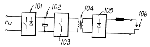
With reference to the accompanying drawings, an exemplary generator
according to the present invention is shown in Figures 5 to 8.
The generator is composed of a set of blocks which in Figure 5 are designated
as input rectifier stage 101, capacitor clamping stage 102, inverter stage
with fast
electronic switches 103, current transformer 104, and power supply stage 105
for
the welding arc 106.
The part that characterizes the generator lies in the input rectifier stage
101,
which is shown in detail in Figures 6, 7 and 8.
In Figure 6, the input stage 101 is shown in a first detail and relates to a
generator with single-phase power supply.
In this circuit configuration there is provided an inductor 107 which is
directly
connected to the mains input 108.
The inductor 107 is followed by two diodes 109 and 110 which are
interconnected in opposition, each diode being served by an electronic switch,
respectively designated by the reference numerals 111 and 112.
The outputs 113 and 114 supply the clamping capacitor stage 102.
In the case of a three-phase power supply, as shown in Figure 7, there are
three
inductors, one for each phase, which are designated by the reference numeral
115,
116 and 117 and are directly connected to the mains 118.
Each one of the inductors is followed by a respective diode 119, 120 and 121,
each of which is served by an electronic switch, designated by the reference
numerals 122, 123 and 124 respectively.
Figure 8 shows in greater detail the structure of the input rectifier stage,
further
illustrating the driver 125 which acts on the switches 111 and 112.
As shown by the path traced in dashed lines, the current (in one of the
operating steps) flows across the inductor 107, the diode 109, the capacitors
102
and the switch 112, which is closed.
CA 02343329 2008-10-23
A similar path occurs when the switch 111 is closed and the diode 110
conducts.
Figure 9 shows the circuit that corresponds to the generator of Figure 3,
5 which comprises a rectifier bridge with four diodes 201, 202, 203 and 204,
an
inductor 205 located downstream of the bridge with respect to the mains input
206,
a further diode 207, a clamping capacitor 208 and a switch 209 controlled by a
driver 210.
In the illustrated conduction step, the current flows across the diode 201,
the
diode 207, the capacitors 208 and the diode 204.
As clearly shown by comparing the path of the current in the two circuits, in
the circuit according to the invention the current passes through only two
semiconductor devices, against the three of the circuit executed according to
the
prior art.
In terms of components, although an extra fast switch is added, the diodes are
reduced to two, against the five provided in the circuit executed according to
the
prior art.
The reduction in the number of semiconductor devices on the one hand reduces
the cost of the generator and on the other hand increases the efficiency
thereof,
since there are lower losses on the semiconductors because of their smaller
number.
From the above description and the drawings, it is evident that a generator
for
welding has been provided which has sinusoidal absorption on the mains side
and
offers improved efficiency and a low cost.
The materials and the components may of course be any according to the size
of the generator.
The disclosures in Italian Patent Application No. PD99A000159 from which
this application claims priority are incorporated herein by reference.