Note: Descriptions are shown in the official language in which they were submitted.
CA 02343605 2004-O1-15
ECP MANIFOLD VENT VALVE INSERT
FIELD OF THE INVENTION
The invention generally relates to valve
assemblies (also referred to as "valve inserts") of the type
deployed within a manifold to control the flow of fluids)
within a system in which the manifold is incorporated. More
particularly, the invention pertains to a vent valve insert
designed to be deployed within a manifold of a freight
railcar equipped with electrically controlled pneumatic
(ECP) brake equipment.
BACKGROUND OF THE INVENTION
The following background information is provided
i
to assist the reader to understand just one of the many
environments in which the invention could be used. 'fhe
terms used herein are not intended to be limited to any
1
CA 02343605 2001-04-04
particular narrow interpretation unless expressly stated
otherwise in this document.
A freight train typically includes one or more
locomotives, a plurality of railcars and several tramlines.
For a freight train headed by a locomotive equipped with an
ECP brake control system, the tramlines include both
pneumatic and electr:i~~al lines some of which run from the
lead locomotive all t:he way to the last rail vehicle in the
train. A pneumatic trainline known as the brake pipe is one
such tramline. It extends the length of the freight train,
as does a two-wire electrical tramline known as the ECP
tramline. Each lc~~omotive also features a multi-wire
electrical tramline known as the multiple unit (MU) line
cable. The MU line cable consists of 27 different
electrical lines. As is well known in the railroad
industry, the MU line cable contains 74V do power and return
lines on which battery power from the locomotive is supplied
to the various power consuming devices on the train.
The brake pipe consists of a series of pipe
lengths, with one pipe length secured to the underside of
each railcar. Each pipe length has, at each of its ends, a
flexible hose with a coupler commonly referred to as a glad
hand. As the locornotive(s) and other rail vehicles are
2
CA 02343605 2001-04-04
coupled in sequence t:o form the freight train, the brake
pipe is formed by connecting the glad hand at the end of
each pipe length to the glad hand of another such pipe
length on an adjacent railcar. Similar to the brake pipe,
the conduit in which the ECP tramline is housed actually
constitutes a series of individual conduits. One such
conduit secured to the underside of each vehicle
interconnects to another such conduit via a connector
between each rail vehicle. Supplied from the 74V do power
line of the MU line cable in the locomotive, the ECP
tramline typically operates at a nominal 230V do t.o power
the ECP brake equipment on each railcar of the freight
train.
The ECP brake control system in the locomotive
includes a cab station unit and a master controller from
which the brakes on the train are ultimately controlled.
The cab station unit. features one or two handles) and/or
push buttons that the train operator uses to direct control
of the brakes. One such handle, known as the automatic
brake handle, can be moved to and between the following
positions: release,, minimum service, full service,
suppression, continuous service, and emergency. Between the
minimum and full sE:rvice positions lies the service zone
3
CA 02343605 2004-O1-15
wherein each incremental movement of the handle toward the
full service position causes an even stronger service
application of the brakes. The force with which the service
brakes will apply depends on how far towards the full
service position the automatic brake handle is moved.
Inputs from the handles) and/or push buttons are
processed by the cab station unit and then passed to the
master controller. Operating according to instructions
contained within its programming code, and in response to
the inputs from the handles) and other sources, the master
controller formulates a brake command appropriate to current
conditions and transmits it along the ECP tramline to each
railcar in the freight train. As specified by the American
Association of Railroads (AAR), the brake commands and other
ECP messages are transmitted from the locomotive using a
powerline communications system such as the Echelon LonWorks
System. Along the ECP trainline, the brake commands) are
then conveyed to the ECP brake equipment on each railcar via
branch wiring. Similarly, in a manner known in the railroad
industry, the brake pipe connects to the ECP brake equipment
on each railcar via a branch pipe.
The master controller can thus order, through the
brake command, any action from a release of brakes to an
4
CA 02343605 2001-04-04
emergency application of brakes or any degree of brake
application in between those two extremes. The brake
equipment may also bE: designed to provide graduated release
of the brakes. The degree of brake application ordered by
the master controll.e:r is typically conveyed in terms of a
percentage of the pressure required for full service brake
application. For example, zero percent (0%) is typically
designated for a release of brakes, 15% for a minimum
service brake application, 100% for a full service brake
application and 120% for an emergency brake application.
The ECP brake equipment on each rail vehicle
typically includes a car control unit (CCU), several
pressure transducE:r_s, various pneumatic and/or
electropneumatic va:Lves, an auxiliary reservoir, an
emergency reservoir, and at least one brake cylinder. Used
to monitor the prest;ures in the brake pipe, the brake
cylinders) and the 'two reservoirs, the transducers convey
electrical signals indicative of those pressures to the CCU.
Each CCIJ :includes a transceiver and a
microprocessor. Controlled by the microprocessor, the
transceiver is conneca:ed via the branch wiring to the ECP
tramline from which :it receives the brake commands issued
by the master controller. The transceiver converts the
CA 02343605 2001-04-04
electrical brake commands into a form usable by the
microprocessor. Operating according to its programming code
and to the dictates of the brake commands and other
electrical signals it has received, the microprocessor
controls the aforementioned electropneumatic valves in a
manner well known in the brake control art. It is through
these electropneumat:i~o valves that air can be maintained
within, exhausted from, or directed from the reservoi.r(s) to
the brake cylinder(s). By moving the automatic brake handle
into service zone, for example, the train operator in the
locomotive will cause: the ECP brake control system to issue
a service brake command along the ECP tramline. In
response to the service brake command, the microprocessor on
each railcar will then route the appropriate amount of air
from the auxiliary reservoir, or, alternatively, the
emergency reservoirs through the appropriate
electropneumatic valves) to the brake cylinder(s).
In addition, as a safety measure, emergency brake
commands are conveyed to the railcars not only electrically
along the ECP trainl:ine but also pneumatically along the
brake pipe. By moving the handle into the emergency
position, the train operator in the locomotive causes the
pressure in the brake pipe to drop at an emergency rate.
6
CA 02343605 2001-04-04
This drop in pressure then quickly propagates along the
brake pipe to each railcar in the train. Should the ECP
equipment lose power or otherwise fail electrically, it will
still respond pneumatically to the telltale reduction in
pressure that occurs in the brake pipe during an emergency.
The ECP brake equipment is designed to respond to the
emergency pressure drop by supplying pressurized air from
both the auxiliary and emergency reservoirs to the brake
cylinders) and thereby cause an emergency application of
the brakes. Absent a command to apply the brakes and under
conditions known in t:he brake control art, the railcar brake
equipment through one of its pneumatic valves charges these
two reservoirs with pressurized air obtained from the brake
pipe.
However prE:ssurized, the brake cylinders) convert
the pressurized air that they receive to mechanical force.
This mechanical force. is transmitted by mechanical linkage
to the brake shoes. Forced against the wheels andJor disc
brakes, the brake shoes are used to slow or stop the
rotation of the wheels. The magnitude of the braking force
applied to the wheels is directly proportional to the
pressure built up in i=he brake cylinder(s).
7
CA 02343605 2001-04-04
As is well known in the railroad industry, an ECP
brake control system is typically employed on a freight
train only as an overlay for or an adjunct of the
conventional pneumatic or electropneumatic (EP) brake
control system. Un_L.ike the ECP brake control system, the
conventional EP brake control system in the locomotive uses
the brake pipe to convey pneumatically to every railcar in
the train all of the brake commands, not just the emergency
commands.
In addition to the cab station unit, the
conventional EP brake control system includes a brake
control computer (BCC) and a pneumatic operating unit (POU).
The BCC responds to th.e signals output by the cab station
unit, i.e., by the handles) and/or push buttons. Based on
these and other signals and on the software that dictates
its operation, the BCC controls the operation of various
pneumatically and electropneumatically operated devices that
comprise the POU. Comprised mainly of pneumatic logic
circuitry and solenoid operated valves, these devices are
commonly referred to as operating portions. It is through
these operating portions that the BCC actually controls the
pressure in the brake pipe (and in various other pneumatic
tramlines and reservoirs).
8
CA 02343605 2001-04-04
The convent::ional pneumatic brake equipment on each
railcar includes a pneumatic brake control valve such as an
ABD, ABDX or ABDW type valve made by the Westinghouse Air
Brake Technologies Corporation (WABTEC). The brake control
valve (BCV) has a service portion and an emergency portion,
both mounted to a pipe bracket. The pipe bracket features a
number of internal passages and several ports. Each port
connects to one of the interconnecting pipes from the
railcar such as those leading to the brake pipe, the brake
cylinders) and the t:wo reservoirs. It i.s through the ports
and internal passages of the pipe bracket that the service
and emergency portions of the BCV communicate fluidly with
the pneumatic piping on the rai:l.car.
By moving the automatic brake handle, the train
operator in the locomotive can control the pressure level in
the brake pipe and thereby direct whether, and to what
extent, the brakes a.re applied. By changing its pressure
level using the automatic brake handle, the brake pipe is
used to convey relea~;e, service and emergency brake commands
to the pneumatic brake equipment on every railcar. In
response to a release brake command (i.e., when brake pipe
pressure is restored to its normal operating pressure), the
service portion of the BCV not only charges the two
9
CA 02343605 2001-04-04
reservoirs with the pressurized air it receives from the
brake pipe but also vents the brake cylinders) to
atmosphere thereby causing the brakes on the railcar to
release. In response to a service brake command (i.e., when
brake pipe pressure is reduced at a service rate), the
service portion supplies air from only the auxiliary
reservoir to the brals:e cylinders) to apply the brakes. How
much the brake pipe pressure is reduced, and thus the
magnitude of the service brake application, depends on how
far the automatic brake handle is moved towards the full
service position. In response to an emergency brake command
(i.e., when the brak:e pipe is vented to atmosphere at an
emergency rate), the service and emergency portions of the
BCV supply air from both reservoirs to the brake cylinders)
to apply the brakes more quickly and forcefully.
Under the control of a conventional EP brake
control system, the brake pipe, or more accurately the
pressure level contained within it, determines whether a BCV
will charge its two reservoirs or deliver pressurized air
previously stored in one or both of its reservoirs to the
brake cylinder(s).
On a freight train equipped with both types of
brake control systems, the train operator in the locomotive
1. 0
CA 02343605 2001-04-04
can thus select whether the conventional EP brake control
system or the ECP brake control system will be used to
operate the brakes. When the conventional braking mode is
selected, the brake pipe is used to convey the brake
commands pneumatically to the pneumatic brake equipment on
each railcar. When the ECP braking mode is selected, the
ECP tramline conveys the brake commands electrically to the
ECP brake equipment on the railcars, with the brake pipe
also being used to convey emergency brake commands as a
safety measure.
Mounted t:o the pipe bracket of the BCV on each
railcar is the ECP manifold assembly, generally designated 1
in Figure 1. Shown only in part, the ECP manifold
assembly 1 includes a manifold 150 and a cover plate 200.
It is within the ECP manifold 150 that at least some of the
aforementioned valves are contained. The ECP manifold 150
contains four boreholes: the cut-out borehole 10, the vent
borehole 30, the auxiliary borehole 50 and the emergency
borehole 70. Boreholes 50 and 70 are often called fill
boreholes. Each of these boreholes has multiple bores, each
of which being of progressively narrower diameter, as viewed
in succession from top to bottom, to accommodate the contour
of the particular valve assembly housed within it.
11
CA 02343605 2001-04-04
The ECP manifold 150 also defines several internal
passages. The emergency passage 2 interconnects the bottom
portion 71 of emergency borehole 70 with the emergency
reservoir on the rai.Lcar. Likewise, the auxiliary passage 3
pneumatically links the bottom portion 51 of auxiliary
borehole 50 to the auxiliary reservoir. Branching off the
auxiliary passage ? is the pilot airway 4. The vent
passage 5 interconnects the middle portion 33 of vent
borehole 30 to atmosphere. The inlet passage 6
interconnects the middle portion 13 of cut-out borehole 10
with the service portion of the BCV. In an ABDX brake
control valve, for example, inlet passage 6 is preferably
connected to the cl., passage in the service portion.
Communicating with. the lower portions 12, 32, 52 and 72 of
boreholes 10, 30, 50 and 70, respectively, is the common
passage 7. The common passage 7 interconnects these lower
portions to the brake cylinder(s).
The ECP manifold 150 houses several valve
assemblies (i.e., ~~valve inserts"). Borehole 10 is used to
house the cut-out valve insert 100. Borehole 30 is used to
house the vent valve insert 300. Borehole 50 is used to
house the auxiliary valve insert 500, and borehole 70 the
emergency insert 700. Valve inserts 500 and 700 are often
12
CA 02343605 2001-04-04
called fill inserts. The inserts shown in Figure 1 emp7,oy a
design that is well known in the art.
The valve inserts are contained within
manifold 150 by cover plate 200. Although only one is
shown, four pilot passages 8 are defined in cover plate 200,
one atop each borehole. Above cut-out insert 100, for
example, pilot pa~;sage 8 communicates with the top
portion 17 of borehole 10. Above valve inserts 300, 500
and 700, the other pilot passages communicate with the top
portions 37, 57 and 77 of boreholes 30, 50 and 70,
respectively.
As best shown in Figures 2 and 3, each valve
insert includes a primary bushing 800 and a piston
assembly 900. The bushing 800 defines a central bore
comprised of upper, middle, and lower cavities 801, 802
and 803. Upper cavity 801 has a larger diameter than middle
cavity 802. ConsequE~ntly, there is an annular ledge at the
bottom of upper cavity 801 where the central bore narrows to
the middle cavity 80<'? . Likewise, there is an annular ledge
at the top of .Lower cavity 803. The primary
bushing 800 also feat:u res two annular valve seats within the
central bore. The first valve seat 810 is formed on the
annular ledge at the bottom of upper cavity 801, and the
13
CA 02343605 2001-04-04
second valve seat 830 is formed on the annular ledge at the
top of lower cavity 803. Each valve seat is flat and formed
at an angle with respect to the longitudinal axis of the
central bore. If viewed 3-dimensionally, each valve seat
would appear as a conic ring-shaped surface.
The primary bushing 800 also has three annular
flanges formed around its periphery. Annular flange 811 is
situated around the top of bushing 800. Annular flanges 812
and 813 are situated around the middle and bottom,
respectively, of bushing 800. The outside diameter of each
flange is identical,. and each flange defines a groove in
which an o-ring is secured. Equipped with its o-rings, the
primary bushing 800 is designed to fit snugly within any of
the boreholes in the ECP manifold 150. The o-rings prevent
leakage between the various portions of the borehole in
which a valve insert :is housed.
The piston assembly 900 is designed to fit within
the central bore of the primary bushing 800. The piston
assembly 900 includes an insert piston 910 and sealing
elements 920 and 9?,Cf. From the head 911 of the piston
extends a shaft 912. The head 911 has an annular collar 913
formed around its periphery. This collar defines a groove
in which an o-ring 9:14 is secured. This o-ring 914 prevents
14
CA 02343605 2001-04-04
air from leaking around the head 911. The head 911 at its
top also has a knob 915.
The shaft 912 has three rims formed around its
periphery. Sealing element 920 is secured around shaft 912
between rim 921 and the underside of head 911, and sealing
element 930 is affixed about shaft 912 between rims 922
and 923. The bottom outside edge of sealing element 920 is
designed to seal f=lush against. first valve seat 810.
Likewise; the top outside edge of sealing element 930 is
designed to seal flush against second valve seat 830.
Sealing element 920 and first valve seat 810 together serve
as an upper valve, and sealing element 930 and second valve
seat 830 together serve as a lower valve.
As best shown in Figure 3, a spring 940 is
disposed around insert: piston 910 in compression between the
underside of collar 97..3 and the ledge at the bottom of upper
cavity 801. This spring biases the insert piston 91U upward
so that. the lower valve is normally closed and the upper
valve is normally open.
The valve inserts shown in Figure 1 are
essentially identica~_, except that valve insert 300 is not
equipped with a secondary insert often referred to as a
booster. Figure 2 shows a valve insert with a booster, and
CA 02343605 2001-04-04
Figure 3 shows one without. The booster, generally
designated 950, has a secondary piston 960 housed within a
secondary bushing 970. At its top, bushing 970 has an
annular lip 971 that limits upward movement of piston 960.
The secondary piston 960 has an annular flange 961
formed around its periphery. This flange defines a groove
in which an o-ring 9E~2 is secured. This o-ring prevents air
from leaking around piston 960. The underside of piston 960
contains a hollow shaft 964. This hollow shaft is designed
to cooperate with the knob 915 of insert piston 910, as
shown in Figure 2.
Mounted to the top of cover plate 200 are four
solenoids, only soler~aid 110 of which is shown in Figure 1.
Above each valve insE:rt, one solenoid communicates with the
pilot airway 4 and the pilot passage 8 for its corresponding
borehole. Each solenoid has an armature stem around which
lies an energi.zable coil. At its head end, the armature
stem has a seal. When the coil is deenergized, the armature
stem has its head end biased against the top of cover
plate 200 above the valve insert. This seals off the pilot
passage 8 from the pilot airway 4 and the auxiliary
reservoir connected. thereto, and thereby prevents
16
CA 02343605 2001-04-04
pressurized air from acting against the top of the valve
insert.
In selecting which brake control system will
direct control of t:he brakes, the train operator in the
locomotive ultimately determines the state of the cut-out
valve insert 100 in ECP manifold 150. When the conventional
EP braking mode is selected, the CCU on each railcar is not
commanded via the ECP tramline to energize the solenoid 110
for cut-out valve insert 100. This leaves cut-out valve
insert 100 in its cut-out state, i.e., its lower valve
closed and its uppE=r valve open. (As is clear from
Figure 1, the lower valve is not used.) Consequently,
whenever the conventional brake control system conveys a
brake application command along the brake pipe, the cut-out
valve insert 100 will. al:Low pressurized air to flow through
its upper valve and into the brake cylinder(s).
Specifically, air from the cl passage in the service portion
of the BCV wil:L be a7_lowed to flow into inlet passage 6 and
through the middle and lower portions 13 and 12 of
borehole 10. The pressurized air will then flow past valve
seat 810 and through common passage 7 into the brake
cylinder(s), and thereby cause the brakes on the railcar to
apply.
17
CA 02343605 2001-04-04
When the EC:P braking mode is selected, the CCU on
each railcar receives a signal via the ECP tra mline to
energize the solenoid 110. When energized, solenoid 110
electromagnetically ~~ompels its armature stem upward, and
thereby interconnect=s the pilot passage 8 of valve
insert 100 to the pilot airway 4. Pilot air from the
auxiliary reservoir then acts against the top of secondary
piston 960. As tree pilot pressure builds, the hollow
shaft 964 encompasses the knob 915 and soon pushes insert
piston 910 downward against the bias of spring 940. This
forces cut-out valve insert 100 into its cut-in state, i.e.,
its upper valve clo~,es. In this state, the cut-out valve
insert 100 cuts off inlet passage 6 from common passage 7,
and thereby disconnects the brake cylinders) from the C1
passage in the service portion of the BCV.
Furthermore, in the ECP braking mode, the brakes
are released or applied only by exhausting or pressurizing
the brake cylinders) through the vent, auxiliary and
emergency valve inserts 300, 500 and 700. The CCU on each
railcar receives the brake release and application commands
via the ECP tramline and energizes the solenoids) above
the appropriate valvE: insert(s).
18
CA 02343605 2001-04-04
Whenever the ECP brake control system conveys a
brake application command along the ECP tramline, for
example, the CCU will energize the solenoid above either
auxiliary valve insert 500 or emergency valve insert 700 or
both. (In practice, it is the emergency valve insert that
is typically activated in response to a service brake
command.) Pilot ai_r from the auxiliary reservoir then acts
against the top of secondary piston 960. As the pilot
pressure builds, the hollow shaft 964 encompasses the
knob 915 and soon pushes insert piston 910 downward against
the bias of spring 940. This forces the emergency valve
insert 700 into its energized state, i.e., its upper valve
closed and its lower valve opened. (As is clear from
Figure 1, the upper valve is not used.) In this state, the
emergency insert 700 <311ows pressurized air to flow from the
emergency reservoir through its lower valve and into the
brake cylinder(s). Specifically, air flows from the
emergency passage 2. into the bottom portion 71 of
borehole '70. The pressurized air then flows past valve
seat 830 through common passage 7 and into the brake
cylinder(s), and thereby causes the brakes to apply.
Whenever the ECP brake control system conveys a
brake release command along the ECP tramline, the CCU will
19
CA 02343605 2001-04-04
energize the solenoid above vent valve insert 300. Pilot
air from the auxiliary reservoir then acts against the top
of insert piston 910. As the pilot pressure builds, the
insert piston 910 moves downward against the bias of
spring 940. This forces the vent valve insert 300 into its
energized state, i.e., its upper valve closed and its lower
valve opened. (As is clear from Figure 1, the upper valve
is not used.) In ths.s state, the vent insert 300 allows the
pressurized air previously developed within the brake
cylinders) to flow through its lower valve to atmosphere.
Specifically, air flows from the brake cylinders(s) through
common passage 7 into the bottom portion 31 of
borehole 30. The pressurized air then flows past valve
seat 830 through vent passage 5 to atmosphere, and thereby
causes the brakes to release.
The cut-out and fill valve inserts 100, 500
and 700 were initial:Ly designed without boosters 950. This
led to problems with the operation of the ECP manifold
assembly 1. For example, when a fill valve 500 or 700 was
returned to its deenergized state (i.e., lower valve closed)
after the brake cylinder was charged, pressurized air from
the brake cylinder was free to flow through common passage 7
past the opened upper valve and work against
CA 02343605 2001-04-04
seal 914 surrounding the underside of head 911.
Unfortunately, the build up of pressure under the head 911
served to resist downward movement of the insert piston 910.
Consequently, to moves the fill valve insert to its energized
state (i.e., lower valve opened), this meant that more pilot
pressure was needed to move the piston insert 911 downward
against the combined forces of spring 940 and the brake
cylinder pressure act.i_ng an the underside of head 911.
It was soon learned, however, that pressure in the
auxiliary reservoir can, under certain conditions, be too
low rel.ati.ve to the brake cylinder pressure to operate the
fill valve properly. Under those conditions, the pilot
pressure (from the reservoir via passage 3, pilot airway 4
and pilot passage 8) acting on the top of head 911 was
insufficient to move the piston assembly 900 downward to the
open position. This meant that no more pressurized air
could be delivered to the brake cylinder when the brakes
were being operated in the ECP braking mode. for this
reason, a booster was added to both the fill and cut-out
valves.
The booster 950 allowed better operation of the
piston assemblies 900 during those times when pressure in
the auxiliary reservoir fell low relative to the brake
21
CA 02343605 2001-04-04
cylinder pressure. ;specifically, as best shown in Figure 2,
the seal 962 around piston 960 of the booster has a larger
surface area than the seal 914 around the head 911 of insert
piston 910. The pi_Lot pressure acting against the larger
effective area atop the secondary piston 960 allows more
downward force to be generated against the piston
assembly 900. (Mult~_plying the effective area of a side of
a piston by the pressure impinging on it gives the force
acting on that side of the pist.on.) This enabled the pilot
pressure to more easily overcome the opposing force caused
by the build up of pressure on the underside of the head 911
of insert piston 910.
Despite the improvement in performance it offered,
the booster did not address all of the problems associated
with the prior art valve inserts. One problem lies with the
pressure imbalance inherent to the design of the cut-out and
fill valve inserts 1.00, S00 and 700. The o-ring seal 914
around the head 911 of insert piston 910 has a relatively
large effective area. It is larger than that of the sealing
element 930 used with the second valve seat 830 to form the
lower valve. This difference in effective area has the
effect of making the piston assembly 900 self-energizing
towards the closed position. As the brake cylinder pressure
22
CA 02343605 2001-04-04
increases, the force on underside of piston
head 911 increases accordingly, and tends to force the lower
valve towards the closed position. Consequently, to
increase the brake cylinder pressure as is needed to apply
the brakes more forcefully, pilot pressure of greater
intensity must be applied atop the secondary piston 960 to
open the valve insert.
Another problem lies with the unguided movement of
the insert piston 910 within the primary bushing 800 for all
of the prior art valve inserts. Rims 921 and 922 each have
a surface angled to comport with its associated seat 810
and 830, respectively, to help guide the movement of insert
piston 910 within the central bore of bushing 800. These
rims, however, do little to prevent the lower end of the
shaft 912 from moving to and fro or left or right, as best
viewed in Figure 2. This is often referred to as the bell
clapper effect. Consequently, when pilot pressure is
removed, rims 921 anct 922 may not always be aligned with the
longitudinal axis of t:he central bore as spring 940 retracts
the insert piston 910 upward. The piston assembly 900 can
then get stuck in the: open position.
23
CA 02343605 2001-04-04
OBJEOTIVES OF THE INVENTION
It is, therefore, an objective of the invention to
provide a vent valve: insert whose design prevents non-
longitudinal movement: of the piston assembly as it is moved
longitudinally within the bushing assembly and thereby
prevents the bell clapper effect suffered by the prior art
vent valve inserts.
A further objective is to provide a vent valve
insert that exhibits a spring load and a valve seat design
that together prov_ic:e a much more reliable seal than the
prior art vent valve inserts, especially at low pressures
and low temperatures.
In additic>rl to the objectives and advantages
listed above, various other objectives and advantages of the
invention will became more readily apparent to persons
skilled in the relevant art from a reading of the detailed
description section of this document. The other objectives
and advantages will become particularly apparent when the
detailed description is considered along with the drawings
and claims presented herein.
SUN~ARY OF THE INVENTION
The foregoing objectives and advantages are
attained by an innovative vent valve insert. In its various
24
CA 02343605 2001-04-04
embodiments, the vent valve insert comprises a bushing
assembly, a piston assembly and a spring. Formed araund the
bushing assembly is a plurality of annular flanges. Each
annular flange defines a groove in which an o-ring is
secured. The o-rings allow the bushing assembly to fit
snugly and sealingly within a suitable borehole, such as the
vent borehole of an ECP manifold assembly. The bushing
assembly defines a longitudinal bore having an upper cavity,
i an intermediate cavit.~r and a lower cavity. It also defines
a first port hole connected to the lower cavity. The
bushing assembly also has a lower spring seat formed
circumferentially at a bottom of the upper cavity. It also
has an annular valve seat formed about the longitudinal
bore. This valve seat faces downward to a bottom area
subjacent to the lower cavity. The annular valve seat
features a raised inner portion tapering off at a
predetermined anglE: to a sloped outer portion.
Reciprocatable within the longitudinal bore between open and
closed positions, the piston assembly comprises an insert
piston and an annular sealing member. The insert piston has
its head disposed in the upper cavity, with its stem
extending downwardly therefrom through the lower cavity.
The head has an annular collar. This collar defines a
CA 02343605 2001-04-04
groove in which a fil°st annular seal is disposed to prevent
leakage around the head. The stem has a bottom portion to
which the annular sealing member is secured. The annular
sealing member has a flat upper surface for sealingly
engaging the raised inner portion of the annular valve seat
when the piston assembly occupies the closed position. The
vent valve insert also features a means for preventing non-
longitudinal movement of the piston assembly as it is moved
longitudinally within the longitudinal bore. Disposed
around the insert piston, the spring lies in compression
between an underside of the annular collar and the lower
spring seat. The spring biases the piston assembly in the
longitudinal bore to the closed position. In the open
position, the piston assembly has pilot pressure acting on a
control surface atop i.ts head. The pilot pressure overcomes
the spring to force 'the annular sealing member downward off
of the annular valsve seat and thereby establish
communication between the lower cavity and the bottom area.
In the absence of pilot pressure, the piston assembly is
returned upward to the closed position by the spring. The
expansion of the sprang pulls the annular sealing member up
against the annular valve seat and thereby cuts off
communication between. the lower cavity and the bottom area.
26
CA 02343605 2001-04-04
BRIEF DESCRIPTION OF THE DRAWINGS
Figure 1 is a cross-sectional view of an ECP
manifold assembly containing four prior art valve inserts,
deployed from left i.o right as a cut-out valve insert, a
vent valve insert and two fill valve inserts.
Figure 2 is an enlarged, cross-sectional view of
the prior art valve insert of Figure I equipped with a
booster.
Figure 3 is an enlarged, cross-sectional view of
the prior art valve insert of Figure 1 not equipped with a
booster.
Figure 4 is a cross-sectional view of a vent valve
insert according to one embodiment of the invention.
Figure 5 is a cross-sectional. view of an ECP
manifold assembly showing, second from left, the vent valve
insert of Figure 4.
Figure 6 i:~ a cross-sectional view of a vent valve
insert according to another embodiment of the invention.
DETAILED DESCRIPTION OF THE INVENTION
Before describing the invention in detail, the
reader is advised that identical components having identical
27
CA 02343605 2001-04-04
functions have been marked, where possible, with the same
reference numerals in each of the accompanying Figures.
This has been done j=or the sake of clarity and to improve
understanding of the ~_nvention.
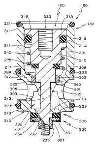
Figures 4 and 5 illustrate one embodiment of the
invention, namely, a vent valve insert, generally
designated 80. ThE: invention is described below as if
intended for the e:zvironment set out in the background
section of this document. Despite being described in the
context of an ECP manifold assembly, it should be apparent
from a reading of this document that the invention may be
implemented in a var_Lety of fluid control systems, even ones
unrelated to the railroad industry. The invention is
presented in this context not to limit the scope of the
claims set forth below but merely to simplify the
description, and thus the understanding, of the invention.
The innovative vent valve insert 80 comprises a
bushing assembly, a piston assembly, a guide ring and a
spring, as best shown in Figure 4. Formed around the
bushing assembly, gE:nerally designated 130, is a plurality
of annular flanges 311, 312 and 313. The flanges are
situated near the top, middle and bottom, respectively, of
bushing assembly 130. Each flange defines a groove around
28
CA 02343605 2001-04-04
its periphery in which an o-ring is secured. The flanges
and o-rings allow the: bushing assembly 130 to fit snugly and
sealingly within a suitable borehole, such as vent
borehole 30 of the E:CP manifold 150 depicted in Figure 5.
The o-rings 321, 32<? and 323 prevent leakage between the
various portions of_ :.he borehole in which the vent valve
insert 80 is to be housed. The top o-ring 321, for example,
provides the seal between the bushing assembly 130 and the
cover plate 200 that covers it.
The bushing assembly 130 defines a longitudinal
bore, generally designated 310, within which to house the
piston assembly. The longitudinal bore 310 has an upper
cavity 301, an intermediate cavity 302 and a lower
cavity 303. Bushing assembly 130 also defines one or more
first port holes) 305 in direct communication with the
lower cavity 303.
Bushing assembly 130 also has a lower spring
seat 306 formed circumferentially at a bottom of upper
cavity 301. It also features an annular valve seat,
generally designated 330, formed circumferentially about the
lower cavity 303. The valve seat 330 faces downward to a
bottom area 30'7 subjacent to the lower
cavity 303. Annular valve seat 330 features a raised inner
29
CA 02343605 2001-04-04
portion 331 tapering off at a predetermined angle to a
sloped outer portion 332. Generally, the predetermined
angle can be in the: range of 25 to 35 degrees. It is
preferably 30 degrees, although it can be adjusted according
to various constraint=s such as the environment in which the
vent valve insert 8U i.s to be used.
'The piston assembly, generally designated 160, is
designed to fit, and be reciprocated longitudinally, within
the longitudinal bore 310 of bushing assembly 130. Piston
assembly 160 includes an insert piston 210 and an annular
sealing member, generally designated 230. Insert piston 210
has its head 211 disposed in upper cavity 301, with its
stem 212 extending downwardly therefrom through lower
cavity 303. The head 211 has an annular collar 213 around
its periphery and defines a chamber 223 within its top. A
groove 215 defined around the annular collar 213
accommodates a first: annular seal 214 to prevent leakage
around the head 211 of insert piston 210.
The guide ring 260 is secured to an interior
cylindrical wall 3:?4 of bushing assembly 130. This
cylindrical wall 324 defines intermediate cavity 302. The
guide ring 260 lies upon an annular ledge 325 at the base of
the cylindrical wall. 324. Figure 4 illustrates a middle
CA 02343605 2001-04-04
portion of stem 212 extending through a throughhole or
aperture 261 defined in guide ring 260. The guide ring 260
prevents non-longitudinal movement of the piston
assembly 160 as i.t is moved longitudinally within
longitudinal bore 310.
The middle portion of stem 212 is dimensioned to
fit and slide smoothly within the aperture of guide
ring 260. Due to it:s precise fit within the aperture 261,
the middle portion of stem 212 prevents the bottom end of
the stem 212 from jostling to and fro or left or right, as
viewed in Figure 4. This design not only guides the
movement of the insert piston 210 within bushing
assembly 130 but a:Lso prevents the bell clapper effect
suffered by the prior art vent valve inserts.
Taken together, the interior cylindrical wall 324
and the guide ring 260 secured therein may essentially be
considered as a means for preventing non-longitudinal
movement of the p:ist.on assembly 160 as it is moved
longitudinally within longitudinal bore 310. It should be
understood that this means could also be implemented using
various other compone:nt.ry and arrangements.
Secured to a bottom portion of stem 212, the
annular sealing member 230 comprises an annular disk 231.
31
CA 02343605 2001-04-04
The annular disk 231 defines a throughhole 232 through which
the bottom portion of stem 212 extends. Comprised of a
resilient material, the disk 231 has a flat surface 233 for
sealingly engaging ;.he raised inner portion 331 of valve
seat 330 when pi.st:on assembly 160 occupies the closed
position within the .Longitudinal bore 310.
Disposed around insert piston 210, the spring 240
lies in compression between an underside of the annular
collar 213 and the lower spring seat 306. It preferably
conveys a load of :3 :Lb., as compared to the 2 lb. load
offered by the springs used with the prior art vent valve
inserts. Spring 240 biases the piston assembly 160 in the
longitudinal bore 310 to the closed position. In the closed
position, piston assembly 160 cuts off lower
cavity 303 from the bottom area 307 subjacent to the lower
cavity. In the open position, the piston assembly allows
communication between the bottom area 307 and the lower
cavity 303.
Referring again to the bushing assembly 130, the
first port holes) 305 are designed to align with the vent
passage 5 in ECP manifold 150. This is best illustrated in
Figure 5, at second from left.. Vent valve insert 80 is
shown housed within the vent borehole 30, with its first
32
CA 02343605 2001-04-04
port holes) 305 in ~~ommunicati.on with the middle portion 33
of vent borehole 30 and therethrough with vent passage 5.
In addition, the bot~~om area 307 is manifested as the bottom
portion 31 of vent borehole 30. The bottom area 307 thus
communicates with the common passage 7 and therethrough with
the brake cylinder ( s ) of the railcar on which the invention
is installed. At the top of head 211 of insert piston 2I0,
the chamber 223 is aligned with the pilot airway 4 in cover
plate 200.
Absent pi:Lot pressure acting against the top
surface 216 of insert piston 210, the spring 240 acts to
force the piston assembly upward within the longitudinal
bore 310. Secured to the bottom portion of stem 212, the
annular sealing member 230 is thus moved upward by
spring 240 so that its flat surface 233 sealingly seats
against the raised inner portion 331 of annular valve
seat 330. The vent valve insert 80 is thus normally biased
to the closed position wherein the lower cavity 303 and the
first port holes) 305 therewith are cut off from bottom
area 307.
When pilot: pressure from pilot airway 4 acts
against the top surface 216 of insert piston 210 and into
chamber 223 defined therein, the piston assembly 160 is
33
CA 02343605 2001-04-04
forced downward aga~_nst the opposing force of spring 240.
The downward movement of insert piston 210 causes the flat
surface 233 of annular sealing member 230 to unseat from the
raised inner portion 331 of annular valve seat 330. Moved
to the open position by the pilot pressure, the piston
assembly 160 allows the lower cavity 303 and the first port
hole ( s ) 305 in communication therewith to communicate with
the bottom area 30'l. When installed within the vent
borehol.e 30 of ECP manifold 150, the vent valve insert 80
when so opened would allow the pressurized air previously
developed within the brake cyl_inder(s) to escape to
atmosphere. Specifically, the air would flow from the brake
cylinders(s) through common passage 7 into the bottom
portion 31 of bor.ehole 30. The pressurized air would
continue to flow pa~;t valve seat 330 into lower cavity 303
and through first port holes) 305 and vent passage 5 to
atmosphere, and thereby cause the brakes of the railcar to
release.
Figure 4 illustrates a backup annular cushion 275.
It also shows an annular recess 217 defined around stem 212
at the base of the head 211 of insert piston 210. Secured
within this recess ;?'17 is the inner portion of the backup
annular cushion 275. When the piston assembly 160 .is moved
34
CA 02343605 2001-04-04
to the open position by the pilot pressure built within
chamber 223, the boi:tom surface of cushion 275 engages the
top surface of guide ring 260.
At the bottom of stem 212, the annular sealing
member 230 has an :internal washer 234 around which the
annular resilient disk 231 is formed. The stem 212 also has
a rim 218 formed around its periphery near the bottom
portion of insert piston 21Ø With the bottom of stem 212
inserted through its throughhole 232, the sealing member 230
is secured by a nut or_ like means 235 to the underside of
this rim 218. The outer surface of rim 218 is angled
downward. This ~eurther aids in guiding the piston
assembly 160 as it. is moved longitudinally within the
longitudinal bore 310.
Figure 6 shows the preferred embodiment of the
invention. In this embodiment, the vent valve insert 81
comprises a bushing assembly 131, a piston assembly 161 and
a spring 240, but not the guide ring. The spring 240 is
unchanged from that used in the previous embodiment. The
bushing and piston assemblies 131 and 161, however, each
have certain features that are different than those of the
earlier described bushing and piston assemblies 130 and 160,
respectively.
CA 02343605 2001-04-04
Regarding the bushing assembly 131, the upper and
lower cavities 301 and 303 are essentially unchanged from
the bushing assembly 130 of Figure 4. The intermediate
cavity 320, however, has a different configuration, as the
guide ring 260 oi= the previous embodiment has been
eliminated. More ;specifically, the interior cylindrical
wall 342 that defines the intermediate cavity 320 is
designed to accommodate a stem 221 of a different design.
Regarding 1=he piston assembly 161, it is designed
to fit, and be reciprocated longitudinally, within the
longitudinal bore 310 of bushing assembly 131. Piston
assembly 161 includes an insert piston 201 and the annular
sealing member 230. The insert piston 201, however, has a
design that differs From the insert piston 210 of Figure 4.
Its head 211 lies within upper cavity 301, and its stem 221
extends downwardly therefrom through lower cavity 303. The
middle portion 251 o:f stem 221, however, defines an annular
groove 253 within which is secured an o-ring 254. The
middle portion 251 is dimensioned to fit and slide smoothly
within the interior cylindrical wall 342 of bushing
assembly 131. Due to its fit within the intermediate
cavity 320, the middle portion 251 of stem 221 prevents the
bottom end of stem 221 from j ostling to and fro or left or
36
CA 02343605 2001-04-04
right, as viewed from the perspective of Figure 6. This
design not only guides the movement of insert piston 201
within bushing assembly 131 but also prevents the bell
clapper effect suffered by the prior art vent valve inserts.
In this preferred embodiment, the o-ring 254 and
the middle portion 251 of stem 221 together serve as a means
of preventing non-longitudinal movement of the piston
assembly 161 as it i.s moved longitudinally within
longitudinal bore 31Ø Along with the cylindrical wall 342
within which they are moved, the o-ring 254 and the middle
portion 251 thus per:~orm the same function as guide ring 260
does for the other embodiment of the invention (i.e., vent
valve insert 80). A vent valve insert that features the
former design is, however, less costly to make and easier to
manufacture than one that features the guide ring design.
The pre:~ently preferred and alternative
embodiments for carrying out the invention have been set
forth in detail according to the Patent Act. Persons of
ordinary skill in the art to which this invention pertains
may nevertheless recognize various alternative ways of
practicing the invention without departing from the spirit
and scope of the following claims. Persons who possess such
skill will also recognize that the foregoing description is
37
CA 02343605 2001-04-04
merely illustrative and not intended to limit any of the
ensuing claims to any particular narrow interpretation.
Accordingly, to promote the progress of science
and the useful arts, I secure for myself by Letters Patent
exclusive rights to all subject matter embraced by the
following claims for the time prescribed by the Patent Act.
38