Note: Descriptions are shown in the official language in which they were submitted.
CA 02343873 2001-04-12
TITLE OF THE INVENTION
ELECTRODE FOR DIELECTROPHORETIC APPARATUS, DIELECTROPHORETIC
APPARATUS, METHOD FOR MANUFACTURING THE SAME, AND METHOD FOR
SEPARATING SUBSTANCES USING THE ELECTRODE OR DIELECTROPHORETIC
APPARATUS
BACKGROUND OF THE INVENTION
This invention relates to an electrode for a
dielectophoretic apparatus , in which a background can be reduced
to enhance an S/N (Signal/Noise) ratio in detecting a substance
to be measured (molecules to be measured) by a fluorescent
strength or the like, a method for manufacturing the same, an
electrode constitution provided with the electrode, and a method
for separating substances using the electrode.
This invention further relates to an dielectrophoretic
apparatus having an enhanced collecting ability, a method for
manufacturing the same, and a method for separating substances
using the apparatus.
Processing technology of materials at scales of nanometer
to micrometer by means of micromachining technology such as
photolithography has recently been established by development
of semiconductor technologies and it has still continued its
progress at present.
In the fields of chemistry and biochemistry, new
CA 02343873 2001-04-12
technology called a Micro Total Analysis System (~.-TAS),
Laboratory on a chip is growing, in which such micromachining
technology is employed to carry out a whole series of
chemical/biochemical analytical steps of extraction of
components) to be analyzed from biological samples (extraction
step), analysis of the components) with chemical/biochemical
reactions) (analysis step), and subsequent separation
(separation step) and detection (detection step) using a highly
small analytical device integrated on a chip having each side
of a few centimeters to a few ten centimeters in length.
Procedures of the p,-TAS are expected to make a large
contribution to saving the analyzing time, reducing the amounts
of samples to be used and reagents for chemical/biochemical
reactions, and reducing the size of analytical instruments and
the space for analysis in the course of all the
chemical/biochemical analytical steps.
For the separation step in ~,-TAS, in particular, there have
been developed capillary electrophoretic methods in which a
capillary (fine tube) with an inner diameter of less than 1 mm
which is made of Teflon, silica, or the like as material is used
as the separating column to achieve separation with charge
differences of substances under a high electric field, and
capillary column chromatographic methods in which a similar
.,
CA 02343873 2001-04-12
capillary is used to achieve separation utilizing the difference
of the interaction between carrier in the column medium and
substances.
However, capillary electrophoretic methods need a high
voltage for separation and have a problem of a low sensitivity
of detection due to a limited capillary volume in the detection
area and also these is found such a problem that they are not
suitable for separation of high molecular weight substances,
though suitable for separation of low molecular weight
substances, since the length of capillary for separation is
limited on the capillary column on a chip and thus a capillary
can not be made into a length enough for separating high molecular
weight substances. In addition, in capillary column
chromatographic methods there is a limit in making the throughput
of separation processing higher and also there is such a problem
that reducing the processing time is difficult.
Thus, attention has recently been paid to a method for
solving the problems as described above, which comprises
utilizing such a phenomenon so-called dielectrophoretic force
that a positive and negative polarization occurs in substances
placed under a non-uniform electric field , thereby providing
a driving force of moving the substances [H. A. Pohl,
"Dielectrophoresis", Cambridge Univ. Press (178); T. B. Jones,
<>
.,
CA 02343873 2001-04-12
"Electromechanics of Particles", Cambridge Univ. Press (1995),
and the like].
These separation methods are presently believed to be the
suitable separation method in ~,-TAS from the following points:
( 1 ) a rapid separation can be expected at a low appl ied voltage
without requiring a high voltage as in capillary electrophoresis,
since an electric field and its gradient can be increased to an
extreme extend if micromachined electrodes are employed, because
the degree of dielectrophoretic forces depends on the size and
dielectric properties of substances (particles) and is
proportional to the electric field gradient; (2) an increase in
temperature due to applying the electric field can be minimized,
since a strong electric field area is localized at a
significantly small region, and a high electric field can be
formed; (3) as the dielectrophoretic force is a force
proportional to the electric field gradient, the force is
understood as independent on the polarity of the applied voltage,
and thus works under an AC electric field in a similar way to
a D.C. electric field, and therefore if a high frequency A.C is
employed, an electrode reaction (electrolyti.c reaction) in an
aqueous solution can be suppressed, so that the electrodes
themselves can be integrated in the channel (sample flow path);
(4) improvement in a detection sensitivity can be expected, since
there is no restriction to a chamber volume of the detection
CA 02343873 2001-04-12
component unlike the capillary electrophoresis, and the like.
The dielectrophoresis termed herein is a phenomenon in
which neutral particles move within non-uniform electric field,
and the force exerting on molecules is called a dielectrophoretic
force. The dielectrophoretic force is divided into two forces,
i.e., a positive dielectrophoretic force in which substances
move toward a high electric field, and a negative
dielectrophoretic force in which substances move toward a low
electric field.
(General Equation of Dielectrophoretic Forces)
The equivalent dipole moment method is a procedure of
analyzing dielectrophoretic forces by substituting induced
charges for an equivalent electric dipole. According to this
method, the dielectrophoretic force F,1 acted upon a spherical
particle with a radius of a which is placed in an electric field
E is given by:
F,~ = 2~a~smRe[K*(co)]v(Ez) (1)
wherein K*(co) means by using an angular frequency of the applied
voltage co and the imaginary unit j as follows:
K* ( c~> ) _~:~,*-~m *~~ E, *+2 ~-m* ( 2 )
CA 02343873 2001-04-12
sP* =sp- j a~,/co, s,~ * _~.~ - j a~/co { 3 )
wherein s~, s,~, aP, and a,~ are permittivity and conductivity of
the particle and the solution, and complex quantities are
designated by *.
Equation ( 1 ) indicates that in a case of Re[K*(co) ] > 0,
the force works in such a way as attracting the particle toward
a strong electric field side (positive dielectrophoretic,
positive DEP), and in a case of Re[K*(cu)] < 0, the force works
in such a way as pushing the particle toward a weak electric field
side (negative dielectrophoretic, negative DEP).
As will be apparent; from the above-described Equations,
whether the positive electrophoresis occurs in a certain
substance or the negative electrophoresis occurs therein is
decided by the interaction of three parameters, i.e., 1)
frequency of an electric field applied, 2) conductivity and
permittivity (dielectric constant) of medium, and 3)
conductivity and permittivity (dielectric constant) of
substance.
When these parameters are changed, even the same substance
shows a positive dielectrophoresis or a negative
CA 02343873 2001-04-12
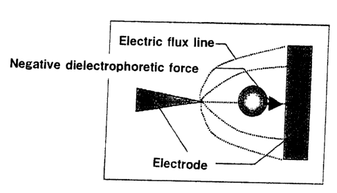
dielectrophoresis. The negative dielectrophoresis is a
phenomenon in which the substance moves toward a low electric
field which is weak in density of electric flux line while the
positive dielectrophoresis moves toward a high electric field
which is high in density of electric flux line . FIG. 1 is a view
for explaining the negative dielectrophoresis. The negative
dielectrophoretic force is a force for carrying substances to
such a field as to be lowered where the density of electric flux
line received by the substance.
Sometimes, the substances are measured by concentrating
them in an area where an electric field on an electrode is weak
by using the negative dielectrophoresis as described and
thereafter measuring them by fluorescent strength or the like .
The detection of the fluorescent strength is carried out by
irradiating an excitation light on the substance to be measured
to observe fluorescent light from the upper surface of the
electrode.
At that time, where a conventional electrode is used, there
poses a problem that the excitation light is reflected even on
the electrode which is present under the substance to be measured,
and thus reflected light is detected as a great background. This
leads to a problem of reducing the measurement sensitivity.
Besides, where a conventional electrode is used, since 1 fight does
not permeate through the electrode, the substances concentrated
(gathered ) on the electrode cannot be detected by absorbance.
CA 02343873 2001-04-12
Further, the dielectrophoresis is contemplated to be a
separation method suitable for,u-'rAS. However, In consideration
of a case of application of the di a 1 ec trophores i s to ,u -TAS, it is
extremely important to enhance the collecting ability. In this
respect, the conventional dielectrophoretic apparatus should not
yet be satisfied.
That is, if the collecting ability of substances is enhanced,
separation becomes enabled in the electrode region, and the
substances are held efficiently, whereby separation with high S/N
(Signal/Noise) ratio is realized. Further, for example, particularly,
in the Field-Flow fractionation for carrying out separation by the
interaction of the dielectrophoretic force and the fluid drag
exerting on the substances, separation in a short electrode region
can be made even at the same flow velocity.
SUMMARY OF THE INVENTION
[INVENTION 1]
It is an object of the present invention to provide an
electrode for a dielectrophoretic apparatus which reduces a
background in which an excitation light is reflected on an
electrode which is present under a substance (a molecule) and
detected to enhance an S/N ratio.
It is a further object of the present invention to provide an
electrode for a dielectrophoretic apparatus, which can be detected
even by absorbance.
CA 02343873 2001-04-12
It is another object of the present invention to provide a
method for separating substances and a detection method using
the above electrode.
For achieving the aforementioned objects, the present
inventors have studied earnestly, as a result of which the
inventors have thought out that an electrode in an area where
substances to be measured are concentrated (gathered) is removed
to thereby enable reduction in background caused by reflection of
an excitation light from the electrode.
In the past, there are many patents and articles in
connection with apparatus and method in a dielectrophoretic
chromatography apparatus (Field-Flow fractionation), but a
dielectrophoretic apparatus and method which reduces a
background by removing an electrode including an area where
substances to be measured are concentrated to enhance an S/N
ratio are not known at all, and such an idea is not known at all.
The present invention is characterized in that by forming a
vacant space in an electrode, substances subjecaed to influence by
a negative dielectrophoretic force generated by application of
voltage to the electrode are concentrated in the vacant space of the
electrode, or above or below position of the space.
The vacant space is formed from a hollow space or formed of
a material which does not substantially reflect excitation light or
permeates light to such an extent as capable of measuring the
absorbance. However, the vacant space is preferably a hollow
0
CA 02343873 2001-04-12
space.
The space where substances subjected to influence by the
negative dielectrophoretic force are concentrated is a space in
which the density of electric flux line is low for the substances.
Further, through all the substances subjected to influence
by the negative dielectrophoretic force are preferably concentrated
in the vacant space, concentrated substances in the vacant space
may be a part of all the substances.
The electrode constitution of the present invention is
characterized by comprising an electrode, and a lid provided
thereabove so as to form a gap between the lid and said electrode
surface, the electrode being formed as in the electrode of the
present invention provided with the vacant space.
The electrode constitution of the present invention includes
an electrode of the present invention, a substrate (an electrode
base plate) and a lid. In the dielectrophoretic apparatus, a device
for applying a voltage to an electrode and a detection section are
added to the electrode or the electrode constitution.
A method for manufacturing an electrode according to the
present invention characterized in that said vacant space is
formed by physical or chemical means.
The separation method and detection method according to
the present invention are characterized in that using the
electrode of the present invention provided with the vacant space,
a liquid including substances subjected to influence by the
CA 02343873 2001-04-12
negative dielectrophoretic force generated by application of
voltage to the electrode is positioned in the electrode or the
vacant space or in the vicinity thereof, or causes to flow
thereabove or therebelow, whereby substances subjected to
influence by the negative dielectrophoretic force are
concentrated(gathered) in the vacant space, or above or below
position of the space.
The separation method of the present invention can be used
for liquids in which two kinds or more of substances are
dissolved or suspended, but preferably, the substances subjected
to influence by the negative dielectrophoresis force
concentrated in the vacant space or in a vertical direction
thereof are granular substances. Because, in the granular
substances, an area in which the density of electric flux line
is low and the granular substances are concentrated tends to be
the vacant space or in a vertical direction thereof.
The vacant space of the present invention, should be formed
in such a way that an area in which the density of a electric
flux line is low and the granular substances are concentrated
may be formed in the vacant space or in a vertical direction
thereof by changing the size of the substances subjected to
influence by the negative dielectrophoresis force, and the width
and depth of an electrode used (the height from the electrode
surface to the 1 id part and or the height from the vessel bottom
to the electrode surface) and frequently applied.
CA 02343873 2001-04-12
However, particularly, where the substances to be measured
are dissolved, for example, in liquid such as water, preferably,
the substances subjected to influence by the negative
dielectrophoresis force are bound to the substances to be
measured in a sample through "substances binding to the
substances to be measured" to form a complex, and a reaction
substance including the complex is applied to the
dielectrophoresis.
It is noted that the substances to be measured used in the
present invention means substances (molecules) to be
concentrated in the area in which the density of electric flux
line is low, and need not always be an object for measurement.
[INVENTION 2]
It is a further object of the present invention to provide,
in an apparatus for enhancing the collecting ability of
substances in which a liquid containing substances to be
separated is present within a non-uniform electric field formed
by a dielectrophoretic electrode to separate the substances by
the dielectrophoretic force exerting on the substrate,
For achieving the aforementioned objects, the present
inventors have studied earnestly, as a result of which the
inventors have thought out that a base plate (substrate) of among
electrodes are excavated to form a part lower than the electrode
level whereby the non-uniform electric field region is increased
and the drag of fluid is reduced to enhance the collecting ability.
CA 02343873 2001-04-12
In the past, there are many patents and articles in
connection with separation apparatus and method making use of
a dielectrophoretic force, particularly, apparatus and method in
Field-Flow fractionation, but an apparatus and method which
enhances the collecting ability by forming "a lower level place
than an electrode level"are not known at all, and such an idea is
not known at all.
Preferably, the present invention provides a
dielectrophoretic apparatus having an electrode provided on a
substrate, wherein means for realizing an increase of an non-
uniform electric field region is formed among the electrodes.
The means for realizing an increase of a non-uniform
electric field region is characterized in that a lower level places
than the electrode level is formed among the electrodes. The
" lower level place than the electrode level" is formed whereby
electric fields are formed not only above between the electrodes
but below thus increasing a non-uniform electric field region, and
further, where for example, Field Flow fractionation is used, since
the flow velocity of fluid in that places drops, the fluid drag is
reduced to enhance the collecting ability of substances.
For forming " lower level places than electrodes level", a
base plate (substrate) may be excavated between electrodes by
physical and / or chemical means to form the lower level place
than the electrode level among the electrodes. The physical means
termed herein is, for example, a method for excavation using a
~:3
CA 02343873 2001-04-12
suitable knife or the like, for example, an LIGA (Lithographile
Galvanoformung Abformung) method using synchrotron radiant
light. Further, the chemical means is etching for excavating a base
plate using an etching liquid for a base plate. Further, for example
a base plate can be excavated by etching using plasma of a
reaction gas [Reactive ion etching (RIE)) formed by a high
frequency power supply, in which a physical excavation and
chemical excavation are conducted at the same time. It is noted
that the means as described above may be suitably combined to
carry out excavation of a base plate.
Further, a separation method according to the present
invention is a separation method for substances in which a liquid
containing substances to be separated is present within a non-
uniform electric field formed by the dielectrophoretic electrode,
and separation is carried out due to a difference in a
dielectrophoretic force exerting on the substances characterized in
that an increase of a non-uniform electric field region is realized
by lower level places than electrode level formed between (or
among) electrodes, to thereby enhance the collecting ability.
Dielectrophoresis (DEP) termed herein is a phenomenon in
which a neutral particle moves within a non-uniform electric
field by interaction of conductivity and dielectric constant of
substances, conductivity and dielectric constant of media, and
frequency applied, and a force acting on the particle is called
a dielectropherotic force. The dielectrophoretic force is
CA 02343873 2001-04-12
divided into two kinds, i.e., a positive dielectrophoretic force
in which substances move toward a high electric field, and a
negative dielectrophoretic force in which substances move toward
a low electric field.
In the following. a. f'.~~P W~1PTP a nnei +; no
dielectrophoretic force exerts on a molecule will be described.
Namely, as shown in Figure 2, a neutral molecule placed
in an electric field has a positively induced polarization charge
+q downstream in the electric field and a negatively induced
polari nation charge -a upstre~.m i n t~lP P 1 Ar+ri ~ f; of ra
respectively, thus +q receives a force of +qE from the electric
field E and this portion is pulled upstream in the electric field.
If the molecule is neutral, +q and -q have an equal absolute value,
and if the electric field is uniform regardless of the positions,
both received forces are balanced, therefore the molecule does
not move. However, in the case where the electric field is
non-uniform , an attractive force toward a strong electric field
becomes larger, thus the molecule is driven toward the strong
side of the electric field.
As described above, the molecule in a solution variously
moves within an electric field according to the
dielectrophoretic force generated in the molecule. However, for
example, in the Field-Flow fractionation, the movement of
>>
CA 02343873 2001-04-12
molecules is governed by three factors: the dielectrophoretic
force F~, the force F~ generated by the drag due to the flow in
the f low path , and the force F,,,, due to the thermal movement .
O in the case of F~, » F~ + F,,~,, molecules are captured (trapped)
on the electrode, O in the case o=f F,, « F~ + Fr,,, molecules are
eluted out with flow in the flow path, regardless of the electric
field. O in the case of F,j . F~ + Ft,,, molecules are carried
downwards with repeating adsorption and desorption on the
electrode, so that the molecules arrive at the outlet with delay,
relative to the set flow in the flow path.
In the present invention, since a portion between
electrodes is excavated deeply whereby a non-uniform electric
field is formed below between the electrodes, the non-uniform
electric field region is increased and the flow of fluid in that
portion becomes slow to reduce the drag force Fv of fluid, whereby
Fd becomes further great under the condition 1~ as described
above and Fv becomes further small thus enhancing the collecting
rate. Further, the particles trapped in the electric field formed
below between electrodes are hard to flow out since the particles
are positioned at " lower level places than electrode level".
The above and other objects and advantages of the invention
will become more apparent from the following description.
BRIEF DESCRIPTION OF THE DRAWINGS
~ r;
CA 02343873 2001-04-12
FIG. 1 is an explanatory view of the negative
dielectrophoresis.
FIG. 2 is a view showing the principle of the positive
dielectrophoresis.
FIG. 3 is a plan view showing an embodiment of an electrode
of the present invention.
F I G. 4 i s a pl an vi ew showing a further embodiment of an
electrode of the present invention.
FIG. 5 is a plan view showing another embodiment of an
electrode of the present invention.
FIG. 6 is a plan view showing an example of a conventional
electrode.
FIG. 7 is a plan view showing a further example of a
conventional electrode.
FIG. 8 is a plan view showing another example of a
conventional electrode.
FIG. 9 is a plan view showing still another example of a
conventional electrode.
FIG. 10 is a plan view showing another example of a
conventional electrode.
FIG. 11 is a plan view showing still another example of
a conventional electrode.
FIG. 12 is an explanatory view in the case where
fluorescent measurement is made according to the method of the
l
CA 02343873 2001-04-12
present invention, (A) showing the case where a fluorescent
measuring unit is provided above, (B) showing the case where a
fluorescent measuring unit is provided below.
FIG. 13 is a plan view showing an electrode of the present
invention prepared in Example 1.
FIG. 14 are respectively, a plan view (A) and a sectional
view {B) showing a further embodiment of the present invention.
FIG. 15 is a sectional view showing an example of " lower
level places than electrode level" of the present invention
formed by isotropic etching (A), anisotropic etching (B), and
RIE or LIGA (C),
FIG. 16 is a plan view showing an electrode used in the
present invention.
FIG. 17 is a sectional view of a dielectrophoretic
chromatography apparatus.
FIG. 18 is a sectional view showing an example of forming
" lower level place than electrode level" on a base plate
(substrate) according to the method of the present invention.
FIG. 19 is a graph showing a relationship between etching
time and the depth of a groove measured in Example 3 .
FIG. 20 is a graph which measured the col letting rate with
respect to bovine-serum albumin (BSA) protein , using the
dielectrophoretic chromatography apparatus according to the
present invention and the conventional dielectrophoretic
chromatography apparatus.
CA 02343873 2001-04-12
F I G. 21 i s a graph whi ch measured the col 1 ec t ing rate wi th
respect to 500bp DNA, using the dielectrophoretic chromatography
apparatus according to the present invention and the
conventional dielectrophoretic chromatography apparatus.
DETAILED DESCRIPTION OF THE PREFERRED EMBODIMENTS
The preferred embodiments of the present invention will
be described hereinafter.
First, the invention 1 will be described in detail
here i naf ter.
FIG. 3 is a plan view showing an embodiment of an electrode
for the dielectrophoretic apparatus of the present invention,
showing an example in which a hollow space (a vacant space) 12
is formed in a part 13 on which are concentrated substances
(substances to be measured) subjected to influence by the
negative dielectrophoretic force generated by an electrode 11
having many hexagonal portions associated.
The hollow space 12 is formed so as to form an area which
is low in density of electric flux line in which the substances
to be measured may be concentrated in the hollow space 12 or in
a vertical direction thereof. The area which is low in density
of electric flux line is an area which is lower in density of
electric flux line than that of an electrode in the circumference,
and in general, an area which is lowest in density of electric
flux line . The size of the hollow space 12 is different depending
CA 02343873 2001-04-12
on the kind and size of substances to be measured, the distance
between an electrode base plate and a cover glass (depth) or the
like, but is generally formed to be larger than a space 13 on
which are concentrated the substances to be measured when the
hollow space is not formed. The hollow space 12 may be
communicated as shown in FIG. 3 or may be independent every
hexagonal portion as shown in FIG. 4.
In the hollow space 12, all the circumference may be
surrounded by the electrode or a break 14 may be present in
a part as shown in FIG. 3, but preferably, al l the circumference
may be surrounded by the electrode.
When all the circumference of the vacant space is
surrounded by the electrode, electric flux lines are generated
from the circumference of the vacant space, and therefore, the
vacant space i s to be surrounded by a high a 1 ectri c f i a 1 d regi on
so that the substances tend to be concentrated on a specific
portion and may be collected easily.
On the other hand, where a space of the vacant space is
not surrounded by the electrode, no line of electric force is
generated from that portion, and therefore, a portion which is
not a high electric field region is generated, and the substances
may be easily moved through that portion. Therefore, there is
a case where the intended substance is hard to be collected.
As the size of substances (particles, molecules) to be
concentrated on the hollow space is small, attention should be
CA 02343873 2001-04-12
paid to the width of an electrode. Because an area above the
electrode will be a portion which is low in density of electric
flux line for the substance than the hollow space. The reason
why is that since a electric flux line is also generated from
an edge of an electrode in contact with the hollow space, a degree
of influence caused by the electric flux Iine generated from an
edge of an electrode in contact with the hollow space is different
depending on the size of the substance. Where the substances to
be concentrated on the hollow space are small, this problem can
be solved by narrowing the width of an electrode having the hol low
space.
The shape of the electrode and the hollow space may be a
circle, oval or a polygon, the shape of which is not particularly
restricted. Also, the width of the electrode itself may be wider
or a thin like a wire. In short, the construction of an electrode
may be employed so that an electrode is not present in an area
in which detected objects subjected to the negative
dielectrophoretic force are concentrated, and in a vertical
direction thereof.
Since even the same electrode construction, there appears
a difference in a region where the measured objects are
concentrated due to the change of the frequency of the electric
field applied, and conductivity and dielectric constant of the
measured object and the medium, the electrode construction may
be decided according to the frequency of the electric field
CA 02343873 2001-04-12
applied according to the using object. Conversely speaking, the
substances to be measured can be concentrated at the desired
position by varying the frequency or the like adjusting to the
electrode construction.
Preferably, the hollow space 12 may be formed in the
electrode, for example, by physical means such as a cutting
method using, for example, a suitable knife or the like and
embossing method, chemical means such as etching for removing
an electrode, for example, using an etching liquid, or for
example, by physical and chemical means such as Reactive Ion
Etching (RIE) using a reactive gas formed into plasma by a high
frequency power supply, and so on.
The electrode formed with the vacant space 12 of the
present invention is preferably prepared, for example, by the
fine processing technique (Biochim. Bophys. Acta. 964,231 - 230
and so on) as described below:
(A) For example, a resist is coated on a base plate having
copper, gold, aluminum or the like laminated thereon, and an
electrode photomask is laminated on the resist. Then, light
is irradiated to expose and develop the resist to dissolve
a resist corresponding to a vacant space and a portion other
than the electrode, which is then dipped into an etching
liquid to apply etching to the electrode surface (aluminum
surface), and the remaining resist on the electrode surface
is removed. It is noted that the resist may be a positive
.,.,
CA 02343873 2001-04-12
resist for removing a portion exposed to light or a negative
resist for removing a portion not exposed.
(B) Lift off method
After a resist is coated on a base plate, an electrode
photomask is laminated on the resist, to which is applied
exposure. Then development is carried out to remove a
resist corresponding to an electrode portion, and an
electrode material is laminated on the whole upper surface
by vapor deposition or sputtering. Then, a resist
corresponding to a portion other than the electrode and
a vacant space (an electrode is laminated on the upper
surface) is removed.
(C) Metal mask method
A metal mask with only the electrode portion applied with
hollowing is laminated on a base plate, on which upper
surface is coated with an electrode material by vapor
deposition or sputtering. Then, the metal mask (an
electrode material is laminated on the upper surface) is
removed.
In the present invention, an electrode is one made of
conductive materials such as, for example, aluminum, gold,
copper and the like. Its structure can be any structure capable
of causing dielectrophoretic forces, that is, forming a
horizontally and vertically non-uniform electric field,
z:~
CA 02343873 2001-04-12
including, for example, an interdigital shape [J. Phys. D: Appl.
Phys. 258, 81-89 (1992); Biochim. Biophys. Acta., 964, 221-230
(1988), and the like).
The electrode of the present invention is, preferably,
formed on the upper surface and /or the lower surface of the base
plate(substrate). Normally, since the liquid containing the
substance to be measured is caused to flow above the electrode,
an electrode formed on the upper surface of the base plate is
used. However, an electrode is placed in a state that floated
in hol low, and the 1 iquid containing the substance to be measured
can be flown below the electrode. In this case, an electrode
formed on the lower surface of a base plate or on both upper and
lower surface of a base plate is used.
The electrodes used in the present invention include, for
example, an electrode in the shape having many electrodes of the
same shape ( hexagon ) assoc i ated, as shown in F I GS . 3 and 4, and
an electrode formed such that a cathode and an anode are provided
internally and externally, respectively, and longitudinal and
lateral parts are made to the same or somewhat different, as shown
in FIG. 5.
Since in the electrode as shown in FIGS. 3 and 4, negative
dielectrophoretic regions can be formed in not only one place
but several places, several hollow spaces having an area which
is low in density of the same electric flux line can be prepared,
CA 02343873 2001-04-12
whereby the fluorescent strength of several places is measured
and averaged to thereby obtain data with reliability.
Further, in an electrode provided with a cathode and an
anode internally and externally, respectively, as shown in FIG.
5, there is one measuring place, but since a space require is
small, that can be contributed to integration of measurement of
many inspected objects.
Other concrete examples of electrodes as shown in FIGS.
3 and 4 include a shape in which many triangular outwardly
projecting parts are associated in a spaced relation opposite
to upper and lower portion of a linear web as shown in FIG. 6,
a shape in which many trapezoidal outwardly projecting parts are
associated in a spaced relation opposite to upper and lower
portion of a linear web as shown in FIG. 7, a shape in which many
hexagons are assoc i ated 1 i near 1 y as shown in F I G. 8, a shape in
which many square outwardly projecting parts are associated in
a spaced relation opposite to upper and lower portion of a linear
web as shown in FIG. 9, and a shape in which many semicircular
outwardly projecting parts are associated in a spaced relation
opposite to upper and lower portion of a linear web as shown in
FIG. 10. While in (A) and (B) in FIGS. 6 to 10, shapes of ends
are different, but either of them will suffice.
Further, other concrete examples of electrodes as shown
in FIG. 5 include, for example, as shown in FIGS. 11 (A) to (G),
electrodes in which an external anode is formed to be polygon
CA 02343873 2001-04-12
such as square and octagon, circle, semi-circle, and oval; and
as an internal cathode, a cathode head located in a central part
of the cathode is formed to be polygon such as square and octagon,
circle and the like. In the present invention, any electrode can
be used as long as the electrode itself can be used for
dielectrophoresis for forming a hollow space, and the kind of
electrodes is not restricted.
A base plate (substrate) used when an electrode is prepared
is not particularly restricted if it can be used in this field,
and a base plate formed of a non-conductive material, for example,
such as glass, plastics, quartz, silicon or the like is
preferred.
The base plate may be formed of a transparent material,
but a material need not always be a transparent material if
excitation light is not substantially reflected, or light is
permeated to such an extent as capable of measuring absorbance.
The electrode may be similar to prior art except formation
of a vacant space, and an organic layer may be formed on the
electrode to prevent adsorption of various materials on the
electrode.
For manufacturing the electrophoretic apparatus of the
present invention using the electrode of the present invention
formed with the vacant space as described above, those other than
the electrode may be formed in a manner similar to prior art.
For embodying the separation method of the present
CA 02343873 2001-04-12
invention using the electrode and the dielectrophoretic
apparatus of the present invention formed with the vacant space
as described above, the separation method itself may be carried
out in a manner similar to prior art.
Namely, a liquid containing substances to be separated,
a liquid in which for example, two or more kinds of substances
(molecules or particles) are dissolved or suspended is placed
in presence within a non-uniform electric field formed using the
electrode as described above, and separation may be accomplished
due to a difference in the dielectrophoretic force exerting on
the substances. It is noted that an electric field applied in the
present invention may be either DC electric field or AC electric
field, but AC electric field is preferred.
In the separation method of the present invention,
granular substances of 100 nm to 100,um are easily concentrated
on an area which is lower in density of electric flux line.
Because the granular substances having the size to some extent
may easily concentrated on an electrode having an area which is
low in density of electric flux line in which substances to be
measured are concentrated in the vacant space and above or below
position of the space. However, it is possible, even when
substances to be separated or measured are small particles or
molecules, to constitute an electrode capable of forming an area
which is low in density of electric flux line :in upper and lower
directions of the vacant space by narrowing the width of an
w
CA 02343873 2001-04-12
electrode or deepening the depth (the distance between the
electrode base plate and the cover glass and / or the distance
from the vessel bottom to the electrode). In short, since the
influence of electric flux line received by particles is
different according to the size of particles, when the particle
having the size to some extent is applied to the separation method
of the present invention, an electrode in which the particles
are concentrated in the vacant space or in upper and lower
directions thereof can be easily formed.
Accordingly, for separating molecules or small particles,
which are measured materials, in a solution of molecules or a
suspension of small particles, a complex in which substances to
be measured (through "substances binding to substances to be
measured" , if necessary) are bound to substances subjected to
influence by the negative dielectrophoretic force, preferably,
granular substances having the size of 100 nm to 100,u m is
subjected to the separation method using a dielectrophoresis.
This is, because of the fact that if the size of particles is
too small, the width of the electrode need be extremely narrowed.
The granular substances are bound as described above
whereby the substances are enlarged, and so, separation of the
substances to be measured is facilitated. Accordingly, the
granular substances function as substances for enhancing
separation.
The granular substance used in the present invention
vs
CA 02343873 2001-04-12
includes inorganic metal oxides such as silica and alumina;
metals such as gold, titanium, iron, and nickel; inorganic metal
oxides and the 1 ike having functional groups introduced by si lane
coupling process and the like; living things such as various
microorganisms and eukaryotic cells; polysaccharides such as
agarose, cellulose, insoluble dextran; synthetic macromolecular
compounds such as polystyrene latex, styrene-butadiene
copolymer, styrene-methacrylate copolymer, acrolein-ethylene
glycol dimethacrylate copolymer, styrene-styrenesufonate latex,
polyacrylamide, polyglycidyl methacrylate, polyacrolein-coated
particles, crosslinked polyacrylonitrile, acrylic or acrylic
ester copolymer, acrylonitrile-butadiene, vinyl chloride-
acrylic ester and polyvinyl acetate-acrylate; relatively large
biological molecules such as erythrocyte, sugars, nucleic acids,
proteins and lipids, and the like.
The "granular substance" are normally bound to "substance
binding to substance to be measured" for use. By doing so, it
can be bound to "substance to be measured" in a sample. However,
the granular substance may be bound directly to the substance
to be measured by a chemical binding method, for example, such
as a method for introducing a functional group into the surface
of the granular substance and afterwards binding through the
functional group, or a binding method the granular substance to
the substance to be measured through a linker.
CA 02343873 2001-04-12
Further, for binding the granular substance to the
"substance binding to the substance to be measured", a method
similar to a method for labeling the measured substance by a
labeling substance described later may be employed.
Where a substance having properties capable of
specifically binding to the substance to be measured directly
is used as the granular substance, the operation as described
above is unnecessary. The granular material as described
includes, for example, neucleic acid, protein, 1 ipid and so on.
The "substance binding to the substance to be measured"
used in the present invention is bound to the granular substance
for use to form a complex of the substance to be measured , the
"substance binding to the substance to be measured", and the
granular substance from the substance to be measured in a sample,
and a complex of a molecule other than the substance to be
measured, the "substance binding to the substance to be measured"
and the granular substance may be not formed substantial ly, which
is not particularly restricted. In short, even if being bound
to the substances other than the substance to be measured, it
will suffice if that may not form the aforesaid three complex
substance. However, it is actually preferred that the "substance
specifically binding to the substance to be measured is used.
A "substance binding to the substance to be measured"
refers to a substance binding to the " substance to be measured
~o
CA 02343873 2001-04-12
" by interactions such as an "antigen"-"antibody" reaction, a
"sugar chain"-"lectin" reaction, an "enzyme"-"inhibitor"
reaction , a "protein"-"peptide chain" reaction, and a
"chromosome or nucleotide chain"-"nucleotide chain" reaction.
If one partner is the substance to be measured in each combination
described above, the other is a "substance binding to the
substance to be measured" as described above.
For forming a complex of binding the substance to be
measured in a sample with the granular substance directly or
through the "substance binding to the substance to be measured",
a sample containing the substance to be measured, the granular
substance and, if necessary the "substance binding to the
substance to be measured" are, for example respectively
dissolved, dispersed or suspended in water or a buffer liquid,
for example, such as tris (hydroxymethyl amino methane)
buffers , a Good' s buffer, a phosphate buffer, borate buffer into
a liquid material, and these liquid material may be mixed and
contacted with each another.
The separation method of the present invention is roughly
divided into two methods as follows:
[Separation method 1]
First, where the substance to be measured, or the complex
of the substance subjected to influence of the negative
dielectrophoretic force (substance for enhancing separation)
CA 02343873 2001-04-12
and the substance to be measured(through "substance binding to
the substance to be measured", if necessary) exhibits the same
negative dielectrophoretic force as that of the substance other
than the substance to be measured, in case of the substance to
be measured or the complex showing the greater dielectrophoretic
force than that of the substance other than the substance to be
measured, only substantially the substance to be measured, or
substance for enhancing separation and the complex of substance
for enhancing separation and the substance to be measured
receive the great dielectrophoretic force and are separated.
Namely, for example, by suitably setting the electric
field strength and the medium conditions in such a way that the
substance to be measured or the complex substance of the
substance subjected to influence of the negative
dielectropherotic force and the substance to be measured(through
"substance binding to the substance to be measured, if necessary)
is concentrated in the vacant space above the dielectropherotic
electrode or in the upper and lower directions thereof, but that
the substances other than the substance to be measured are not
concentrated , these substance to be measured and the substance
other than the substance to be measured can be separated.
The method of the present invention is suited for
separation in the state free from flow. However, the so-called
dielectrophoretic chromatography apparatus (Field Flow
Fractionation apparatus) which carries out separation by the
CA 02343873 2001-04-12
interaction of the dielectrophoretic force generated in
molecules by the electric field and the movement of molecules,
may be used to carry out separation. In this case, by suitably
setting the flow velocity (speed is made slow) in such a way that
only substance to be measured or the complex of the substance
subjected to influence of the negative dielectrophoretic force
and the substance to be measured ( through "substance binding to
the substance to be measured, if necessary) is collected in the
vacant space of the electrode or in the upper and lower directions
by the dielectrophoretic force , these substance to be measured
and the substances other than the substance to be measured can
be separated. In the condi tion that the substance trapped in the
hollow space of the electrode or in the upper and lower directions
thereof is not moved by the flow, many samples can be applied
to the hollow space of the electrode by the measurement in the
flow, thus enhancing the measurement sensitivity.
[Separation method 2]
Second, where the substance to be measured or the complex
of the substance subjected to influence by the negative
dielectropherotic force and the substance to be measured
(through "substance binding to the substance to be measured",
if necessary) is one subjected to influence by the negative
dielectropherotic force different from substances other than the
substance to be measured, namely where the substance to be
measured or the complex of the substance for enhancing separation
:3;
CA 02343873 2001-04-12
(substance subjected to influence by the negative
dielectropherotic force) and the substance to be measured
exhibits the negative dielectropherotic force and the substances
other than the substance to be measured exhibits the positive
dielectropherotic force, either of 1~ the substance to be
measured or the complex of the substance to be measured and the
substance subjected to influence by the negative
dielectropherotic force and ~ the substances other than the
substance to be measured moves to the hollow space or in the
upper and lower directions thereof while the other moves to a
different electrode region whereby the substance to be measured
can be separated from the substances other than the substance
to be measured.
When the substance to be measured separated by the
separation method according to the present invention can be
detected by a method according to properties own by the substance,
the presence or absence of the substance to be measured contained
in a sample can be measured (detected).
Namely, using the dielectrode according to the present
invention, the dielectrode constitution and the
dielectrophororetic apparatus, a liquid material(sample)
containing the substance subjected to influence by the negative
dielectropherotic force generated by application of voltage to
the electrode [or substance to be measured or the complex of the
substance for enhancing separation and substance to measured
CA 02343873 2001-04-12
( through "substance binding to the substance to be measured, if
necessary') ] is located at the electrode according to the
present invention, or the vacant space or in the vicinity thereof,
or is caused to flow above or below thereof, whereby the
substances subjected to influence by the negative
dielectrophoretic force are concentrated on the vacant space,
above or below thereof, and afterwards, the substance to be
measured in a sample can be detected by optically detecting the
substance.
The substance to be measured in the above-described method
is that can be measured by any optical method, or that can be
labeled by an optically detectable labeling substance, or bound
to the "substance binding to the substance to be measured" that
can be measured (detected), or that can be labeled by an optically
detectable labeling substance.
In the present invention, the substance to be measured or
the "substance binding to the substance to be measured" may be
labeled by the optically detectable labeling substance, and
labeling itself may be carried out by a well-known labeling
method generally carried out in a conventional method generally
used in the field of, for example, well-known EIA, RIA, FIA or
a hybridization method.
The optically detectable labeling substances which can be
used in the present invention are any substances usually used
:;
CA 02343873 2001-04-12
in the art of enzyme immunoassay (EIA), fluoroimmunoassay(FIA),
hybridization method, and the like, and are not particularly
limited. However, the labeling substance capable of being
detected by the fluorescent strength, the light emission
strength or the absorbance is particularly preferred.
In the above-described method, as the "substance binding
to the substance to be measured", the "substance binding to the
substance to be measured" that can be measured (detected) by any
optically detectable method or that can be labeled by an
optically detectable labeling substance is generally used.
More concretely, the detection method according to the
present invention may be carried out in a manner as described
below.
The substance to be measured or the complex of the
substance to be measured and the separation enhancing substance
(if necessary, through the substance binding to the substance
to be measured and/or the substance binding to the substance to
be measured labeled by the optically detectable labeling
substance) obtained by reacting the substance to be measured
and the separation enhancing substance (if necessary, and the
substance binding to the substance to be measured and/or the
substance binding to the measured substance labeled by the
optically detectable labeling substance) and the substances
other than the substance to be measured (for example, the free
substance binding to the substance to be measured or the free
CA 02343873 2001-04-12
labeled substance to binding the substance to be measured ) are
separated according to the separation method of the present
invention as mentioned above. Next, the separated substance to
be measured or the separated complex is optically detected on
the basis of properties of the substance to be measured or the
substance binding to the substance to be measured (or the
labeling substance binding to the substance binding to the
substance to be measured in the complex) in the complex to measure
the presence or absence of the substance to be measured in the
sample.
Further, according to the present invention, not only the
presence of the substance to be measured in the sample can be
detected, but also the amount of the substance to be measured
in the sample can be measured quantitatively. The quantitative
measurement of the substance to be measured may be done similarly
to prior art where the complex is not formed, and in case where
the complex substance is formed, the following method may be
employed.
That is, the substance to be measured or the complex of
the substance to be measured and the separation enhancing
substance (if necessary, through the substance binding to the
substance to be measured and/or the labeled substance binding
to the measured substance) and the substances other than the
substance to be measured [for example, the free substance binding
to the substance to be measured (or the free labeled substance
:;;
CA 02343873 2001-04-12
binding to the substance to be measured )] are separated
according to the separation method of the present invention as
described above. Next, the amount of the separated substance to
be measured or the substance binding to the substance to be
measured in the complex (or the optically detectable labeling
substance binding to the substance binding to the substance to
be measured in the complex ), or the amount of the free substance
binding to the substance to be measured (or the optically
detectable labeling substance binding to the free labeled
substance binding to the substance to be measured) are obtained
by the optical measurement method according to these properties,
and the amount of the substance to be measured in the sample can
be obtained on the basis of the obtained amount.
In the above-described method, in order to obtain the
amount of the substance to be measured in the sample on the basis
of obtained amounts of the substance to be measured, the
substance binding to the substance to be measured or the labeling
substance, for example, the quantity of specific molecules in
the sample may be calculated, by using a calibration curve
showing a relationship between the amount of the substance to
be measured, and the amount of the substance binding to the
substance to be measured in the complex (or the labeled substance
binding to the substance to be measured) or the amount of the
free substance binding to the substance to be measured (or the
optically detectable labeling substance in the labeled substance
CA 02343873 2001-04-12
binding to the substance to be measured ), obtained by carrying
out the same measuring method mentioned above except for using
a sample whose concentration of the substance to be measured is
known.
According to the present invention, the substance to be
measured ( molecules to be measured) can be concentrated in the
hol low space of the electrode or in the upper and lower directions
thereof. When the excitation light is irradiated on the
concentrated measured molecules, since the electrode is not
present under the molecules, the background caused by being
reflected even on the electrode is not detected, as compared with
the case using the conventional electrode, as shown in FIG. 12(A).
As a result, the S/N ratio is enhanced, as compared with prior
art and the measuring sensitivity is enhanced.
Further, if the electrode of the present invention is used,
since the electrode is not present under the substances to be
measured , a fluorescent detector can be provided on the opposite
side as shown in FIG. 12 (B). Further where it is provided on
the opposite side, the S/N ratio is enhanced (slit effect) since
the parts other than the region where the substances to be
measured are concentrated are covered with the electrode,
whereby in said parts the excitation light irradiated from the
upper surface does not reach the lower surface, and therefore,
the background can be reduced.
Further, according to the present invention, since the
3
CA 02343873 2001-04-12
measurement can be done from the lower surface, the absorbance
of the substances to be measured is measured, which has been
heretofore impossible, to enable qaualitative (detection) and
quantitative measurement of the substances to be measured.
In this case, the S/N ratio is further enhanced (slit
effect) since the parts other than the region where the
substances to be measured are concentrated are covered with the
electrode, whereby in said parts light does not permeate through
the electrode from the upper surface to the lower surface, and
therefore, the background can be further reduced.
In the following, the invention 2 will be described in
detail.
FIG. 14 shows an embodiment of the present invention,
showing an example in which an electrode 3 is supported in a
lengthwise spaced relation by a convex member 2 (a support
column) on a substrate(a glass substrate) 1.
A " lower level place than electrode level" (a
communication groove) 4 which is semicircular in section is
formed between the electrodes 3, 3 , as shown in FIG. 14 (B),
and communication grooves 4, 4 adjacent to each other are
communicated at parts other than the convex member 2, as shown
in FIG. 14 (A). However, alternatively, the electrode 3 is
supported by a wall (a convex member) 2', and grooves 4', 4'
adjacent to each other are isolated by the wall 2' so as not to
be communicated, as shown in FIG. 15 (B).
~o
CA 02343873 2001-04-12
In the embodiments shown in FIGS. 14 and 15, portions other
than the convex members 2 and 2' are formed on the " lower level
place than electrode 3 level" (4 and 4').
However, a concave portion (hole) may be singly or in
plural in a spaced relation provided in a part between the
electrodes 3, 3, but preferably, the whole or a major portion
between or among electrodes is formed in a lower level place than
the a 1 ec trode ( 4 or 4' ) 1 eve 1 as shown i n F I GS . 14 and 15 to
enhance
the collecting ability.
Where the concave portion (hole) is formed in a part
between the electrodes 3, 3, preferably, it may be formed in a
minimum gap 5 between the electrodes. Since this portion is high
in electric field strength, if the concave portion (whole) is
formed in this portion, the collecting ability is further
enhanced. However, if that is formed in the whole including this
portion, further the collecting ability can be enhanced, because
a portion for trapping molecules increases.
The width of the groove 4 (the same as the distance between
the electrodes 3, 3 in the case shown in FIGS. 14 and 15) is
suitably decided according to the size of substances as separated
substances by the dielectrophoresis and is said absolutely
though giving great effect to the electric field strength. In
the substance of the size which is micrometer, the width is
preferably, 1 time to 100 times of the diameter of the substance,
more preferably, 1 time to 10 times. Further, in case of a bio-
m
CA 02343873 2001-04-12
molecule such as a protein, a gene or the like, for example, such
as a peptide, a protein or the like, normally, the width is lnm
to 10 ,um, preferably lnm to 5,um. In case of nucleotide chain
(polynucleotide, oligonucleotide), normally, the width is 1 nm
to 100,um, preferably 1 nm to 50,um.
Generally, if the depth is deeper, a portion for trapping
a molecule increases. Further, particularly, in case of
Field-Flow fractionation, the flow velocity at the groove
portion is suppressed to enhance the collecting ability
(collecting rate). However, if being too deep, where it is
necessary to measure a molecule trapped on the electrode by the
dielectrophororesis, the molecule trapped is sometimes hard to
be released from the groove portion or not released. Accordingly,
the depth of the groove is, preferably, 1/ 1000 times to 10 times
of the width of the groove, more preferably, 1/ 1000 times to
1 time.
With respect to the depth of the groove, if isotropic
etching is used for formation as shown in FIGS. 14 and 15, when
the groove is made more than the width of the electrode, the
convex member which holds the electrode is totally dug away
whereby the electrode 3 is peeled off. Accordingly, when the
groove i s formed by thi s method, the depth of the groove i s set
to 1/2 or less of the maximum electrode width.
Where anisotropic etching of a silicon wafer is used for
formation, as shown in FIG. 15 (B), etching progresses only in
,,.
CA 02343873 2001-04-12
a direction of depth at an angle of about 55 degrees. Accordingly,
where etching is made by this method, the maximum distance
depthwise (the distance between electrodes= 2) x 1.42 (tan 55
degrees) results.
As shown in FIG. 15 (C), where formation is made by RIE
or LIGA, etching progresses substantially vertically.
Accordingly, where etching is made by these methods, the depth
of the groove is in the range described above, namely, preferably,
1/1000 times to 10 times, more preferably 1/1000 times to 1 time.
The spac i ng of the groove ( = w i dth of the a 1 ec trode i tse 1 f )
is not affected by the separated object if limiting to separation
by the positive dielectrophororesis. It is normally from the
processing accuracy in the fine processing technique to lnm to
50,um, more preferably, lnm to l0,um.
The groove by the isotropic etching shown in FIG. 15 (A)
is formed by etching a glass base plate or a plastic base plate.
In the isotropic etching, various shapes are formed according
to the extent of etching such as the case where the electrode
3 is supported by the wall 2 on the base plate and the grooves
4, 4 adjacent to each other are formed so as to be isolated by
the wall 2, or the case where the electrode 3 is supported by
the convex member 2 on the base plate, and the grooves
(communication grooves) 4, 4 adjacent to each other are
communicated.
The groove by the anisotropic etching shown in FIG. 15 (B)
CA 02343873 2001-04-12
is formed by etching a silicon base plate. In this case, the
electrode 3 is supported on the wall 2' on the base plate, and
the grooves 4', 4' adjacent to each other are isolated by the wall
2'
The groove by RIE shown in FIG. 15 (C) is formed by etching
a silicon or SiOZ base plate, and the groove by LIGA is formed
by etching polymer, ceramic, plastic base plate etc. In these
cases, the electrode 3 is supported on the wall 2" on the base
plate, and the grooves 4", 4" adjacent to each other are isolated
by the wall 2".
In the isotropic etching shown in FIGS. 14 and 15(A),
generally, the groove or the communication groove 4 is formed
to have a shape whose section is semicircular, or semi-oval . When
a groove is formed by the anisotropic etching shown in 15 (B),
generally, the groove 4' is subjected to etching into a
substantially V-shape finally via a substantially trapezoid in
section. When a groove is formed by RIE or LIGA shown in FIG.
15 (C), generally, etching is made to a substantially square in
section. Accordingly, various sectional shapes are formed
according to the way of etching and the way of forming "a lower
level place than electrode level", but in the present invention,
the shape of "a lower level place than electrode level" (such
as a communication groove, a groove, a concave part, etc.) are
not particularly limited.
A wall or a convex member 2 in FIG. 15 (A) is formed into
~ -1
CA 02343873 2001-04-12
a shape in which a centrai part is bound; a wall 2' in FIG. 15
(B) is formed into a trapezoidal shape; and a wall 2" in FIG.
15 (C) is formed into a square shape, but the wall, the convex
member 2, the wall 2', and the wall 2" may be any shape as long
as they can support the electrode 3, and are not particularly
limited.
The electrode 3 used in the present invention is formed
of a conductive material, for example, such as aluminum, gold
or the like, and the construction thereof will suffice to be one
which produce the dielectrophoretic force, that is, a non-
uniform electric field in horizontal and vertical directions,
for example, an interdigital shape [J. Phys. D: Appl. Phys. 258,
81-88, (1992), Biochim. Biophys. Acta. 964, 221-230, (1988),
etc.] being listed.
More concretely, preferable are, as shown in FIG. 16, (A)
a shape in which many triangular outwardly projecting parts 7a
are formed in a spaced relation opposite to upper and lower parts
of a linear web-like part 6; (B) a shape in which many square
outwardly projecting parts 7b are formed in a spaced relation
opposite to upper and lower parts of a linear web-like part 6;
(C) a shape in which many trapezoidal outwardly projecting parts
7c are formed in a spaced relation opposite to upper and lower
parts of a linear web-like part 6; (D) being sine wave shape at
upper and lower portions, a shape in which many sine wave convex
parts 8 and concave parts 9 (concave part 9 and convex part 8)
n>
CA 02343873 2001-04-12
are formed linearly opposite to upper and lower portions; and
(E) being saw-tooth shape at upper and lower portions, a shape
in which many convex parts 8' of saw-tooth and concave parts 9'
(concave part 9' and convex part 8') are formed linearly opposite
to upper and lower portions. However, any shape can be used if
the electrode can be used for dielectrophoresis, and the shapes
are not particularly limited.
Such an electrode as described is normally prepared by
providing a pair or more electrodes having shapes as described
above on comb-tooth-wise on a base plate formed of a non-
conductive material, for example, such as glass, plastic, quartz,
silicon, etc. by using known fine processing technique [Bichim.
Bioophys. Acta., 964, 221-230, etc.]. Further, the distance
between the electrodes 3 opposite (adjacent) to each other is
not particularly limited as long as a non-uniform AC electric
field of strong electric field strength can be formed, and should
be suitably set according to the kind of molecules intended.
The thickness of the electrode 3 may be similar to prior
art, and concretely, the thickness is normally 0.5 nm or more,
preferably, 0.5 nm to 1000 nm, more preferably, 1 nm to 1000 nm.
The electrode 3 may be similar to prior art except the
thickness, and an organic layer may be formed on the electrode
in order to prevent adsorption of various materials on the
electrode.
The dielectrophoretic apparatus according to the present
a es
CA 02343873 2001-04-12
invention may be manufactured in a manner similar to prior art
except "a lower level place than electrode level" (such as a
communication groove 4, a groove 4', a concave portion etc. ) such
as a flow path and a dielectrophoretic electrode.
The " lower level place than electrode level" may be formed,
for example, by excavating a base plate between electrodes by
means of physical means such as an excavating method using a
suitable knife or the like , a LIGA (Lithographile Galvanoformung
Abformung) method using a synchrotron radiant light and an
embossing method using a suitable embossing die ; chemical means
for excavating a base plate, for example, using an etching liquid
for a base plate; or physical and chemical means such as etching
using reactive gases formed into plasma by a high frequency power
supply [Reactive Ion Etching (RIE)].
It is noted that the above-described means may be combined
suitably to carry out excavation of a substrate.
As an etching liquid, a known etching liquid may be
selected according to material of a substrate. Where a lower
level place than electrode level is formed in a part of a
substrate, etching may be accomplished with masking is suitably
applied to a portion which is not desired to be excavated.
For embodying the separation method of the present
invention using the dielectrophoretic apparatus according to the
present invention, the separation method itself is the same as
prior art.
1r
CA 02343873 2001-04-12
That is, a liquid containing a substance to be separated,
for example, a 1 iquid in which more than two kinds of substances
(molecules or particles) are dissolved or suspended is present
in a non-uniform electric field formed using the electrode
(electrode base plate) as described above whereby separation may
be accomplished by a difference of the dielectrophoretic force
exerting on the substances.
Generally, a non-uniform electric field is formed
horizontally and vertically within a flow path on the substrate
to cause to f low a 1 iquid containing a substance to be separated
from an inlet, and separation may be accomplished by a difference
of the dielectrophoretic force exerting on the substances.
However, of course, the substance may be separated into a
component held in a specific portion of an electrode and a
component not held for carrying out separation without
generating a flow.
For separating by a difference of the dielectrophoretic
force exerting on the substances (molecules, particles), the
substance may be separated into a molecule etc. held in a specific
portion of an electrode and a molecule etc. not held. Or, since
molecules subjected to a stronger dielectrophoretic force move
later than molecules subjected to a weak dielectrophoretic force,
separation may be accomplished making use of the fact that a
difference is produced in moving time.
As shown by an arrow in FIG. 17, when a liquid containing
CA 02343873 2001-04-12
a substance to be separated in a direction crossing the
lengthwise of an electrode is caused to flow into a flow path
of the apparatus according to the present invention, the flow
velocity in the communication passage (groove) 4 becomes slower
than that of the flow path portion so that the drag Fv of fluid
applied to the molecule entered the communication groove 4 can
be reduced. Further, by the provision of the communication groove
4 between the electrodes 3, 3, the range affected by the electric
field becomes widened, and the space where the trapped molecules
are stocked becomes widened whereby the collecting rate
(ability) is enhanced.
The measuring method of the present invention may be
carried out in conformation with the known method as described
above other than that using the separation method of the present
invention, and the reagents used may be suitably selected from
the well-known reagents.
While the present invention will be further described
hereinafter concretely with reference to examples and
reference examples, the present invention is not at all limited
thereto.
[EXAMPLES)
EXAMPLE 1: Preparation of an electrode of the present invention
formed with a vacant space by etching
The electrode according to the present invention was
prepared by coating a resist on a glass base plate applied with
CA 02343873 2001-04-12
aluminum vapor deposition, then exposing through laminating a
photomask having an electrode and vacant space pattern depicted
by an electron beam depicting device on the resist, and
developing the resist, dissolving a resist film corresponding
to the vacant space and portions other than the electrode, and
thereafter dipping it into an etching liquid to apply etching
to an aluminum surface, and removing the resist remained on the
aluminum surface to form an electrode having a vacant space shown
in FIG. 13.
The pattern of the vacant space was changed to prepare electrodes
1 to 4 different in length (,u m) of a) to e) in FIG. 13. Table
1 shows the length (,um) of a) to e) of electrodes 1 to 4 prepared.
Table1
Electrode 1 Electrode 2 Electrode 3 Electrode
4
(,um) (,um) (,um) (,um)
a 14 8 8 8
b 8 2 2 2
c 5 5 10 15
d 2 2 2 2
a 3.5 3.5 3.5 3.5
EXAMPLE 2: Dielectrophoretic test of beads on a hollow electrode
Where beads having a diameter of l,c.cm was subjected to
dielectrophoresis using a conventional electrode, beads are
concentrated (gathered ) at a position on the electrode whose
:,o
CA 02343873 2001-04-12
field strength is weak. In the design of the electrode prepared
in Example 1, the aluminum electrode portion in a region where
the beads are gathered are excluded.
A dielectrophoretic test was conducted under the electric
field that the beads show the negative dielectrophoresis on the
electrode (electrode 2 in Table 1 ) prepared in Example 1, using
beads having a diameter of 1 ,u m with the fluorescent-labeled
surface thereof.
A sample solution with the beads suspended was dropped
above the electrode substrate(hollow space), and afterward, a
cover glass was put, and observation was made by an optical
microscope.
As a result of observation of the dielectrophoretic test,
it has been confirmed that the beads were concentrated in the
hollow space (vacant space) of the electrode by the negative
dielectrophoretic force. The beads were concentrated while
floating in the solution above the hollow space (near the cover
glass).
Reference Example 1:
Manufacture of dielectrophoretic electrode substrate
A multi-electrode array having a minimum gap of 7,u m, an
electrode pitch of 20,u m, and the number of electrodes of 2016
(1008 pairs) was designed, and a photomask according to the
>>
CA 02343873 2001-04-12
design was made for manufacturing the electrode as .follows.
On a glass substrate on which aluminum was deposited and
to which a photoresist was applied, an electrode pattern as
designed was drawn on an electron beam drawing machine, and then
the photoresist was developed and the aluminum was etched to make
the photomask.
The electrode substrate was manufactured according to the
method described in T. Hashimoto, "Illustrative
Photofabrication", Sogo-denshi Publication (1985), as follows.
The photomask thus made was contacted tightly with the
aluminum-deposited glass substrate to which a photoresist was
applied, and then exposed to the electrode pattern with a mercury
lamp. The electrode substrate was manufactured by developing
the exposed glass substrate for the electrode and etching the
aluminum surface, followed by removing the photoresist remained
on the aluminum surface.
EXAMPLE 3: Formation of " lower level place than electrode level"
on a substrate by etching
As shown in FIG. 18, etching was applied to the glass
substrate 1 of the dielect.rophororetic electrode prepared in a
manner described in Reference Example 1 to form a communication
r~ .~
CA 02343873 2001-04-12
groove 4 in a portion among the electrodes 3 on the glass
substrate 1.
As an etching liquid, sodium fluoride sulfuric acid (NH~F
3%, H2S0~, H20) was used. Sodium fluoride sulfuric acid has
properties to dissolve both glass and aluminum, but since the
speed for etching glass is very quick as compared with that for
etching aluminum, a glass portion other than the aluminum
electrode can be subjected to etching with an aluminum electrode
as a mask.
It is observed that in case where the thickness of aluminum
of an electrode is 40nm, when etching to the depth of 3,u m or
more is done, an electrode is bent by a flow of water when the
etching liquid is washed with pure water. However, in case of
thickness of 250 nm, the phenomena that the electrode is bent
was not observed.
A relationship between an etching time (sec, ) and the depth
(,um) of a communication groove formed between electrodes, upon
etching, was measured. The result indicated that the etching time
and the depth of a groove to be formed are in a proportional
relation as shown in FIG.19. The depth of a groove was measured
by cutting an electrode with a glass cutter and observing its
section with a microscope.
Reference Example 2:
Manufacturing an electrode substrate having a flow path
,:3
CA 02343873 2001-04-12
In order to separate molecules by the movement of the
molecules under an non-uniform electric field, a flow path on
the electrode substrate manufactured in Example 3 was made using
silicone rubber.
The silicone-rubber flow path for sending a solution
containing dissolved molecule on the electrode had a depth of
25,um and a width of 400,um and was designed such that the flow
path runs through a region in which the electrode on the electrode
substrate was placed.
Its manufacturing was carried out according to the method
described in T. Hashimoto, "Illustrative Photofabrication",
Sogo-denshi Publication (1985). At first, a sheet-type
negative photoresist having a thickness of 25,ccm was applied onto
the glass substrate, exposed through a photomask designed for
making the flow path, and the negative photoresist was developed.
Uncured silicone rubber was cast using the negative-photoresist
substrate as a template, and then was cured to produce a silicon
rubber surface having the concave surface with a height of 25
,u m in the region where the electrode was placed.
The electrode substrate and the silicone-rubber flow path
were adhered with a two-fluid-type curing silicone rubber such
that the concave surf ace of the s i 1 i cone rubber was faced to the
r~,~
CA 02343873 2001-04-12
region where the electrode on the electrode substrate was placed.
A syringe for injecting a solution was placed upstream of the
flow path, and an apparatus allowing a solution in which the
molecules were dissolved to flow on the electrode was added to
the electrode substrate.
EXAMPLE 4: Measurement of collecting rate with respect to
bovine-serum albumin (BSA) protein
An electrode formed with a communication groove having the
depth of 2,u m or 4,u m was prepared as in Example 3, a flow path
was prepared as in Reference Example 2, a dielectrophoretic
chromatography device of the present invention was prepared, and
the collecting rate of the device was measured in the following
manner. For the purpose of comparison, with respect to the
dielectrophoretic chromatography device prepared similarly
except that a communication groove is not formed, the collecting
rate was also measured.
(Sample)
As a sample, a solution containing FITC labeled BSA
(molecular weight: approximately 65 kD) (60,u g/ml )was used.
(Operation)
For preventing adsorption of protein molecules to the
electrode substrate or flow path, a block A (manufactured by Snow
Brand Mi lk Products C0. , L td. ) was used to block the surface of
the flow path, after which FITC labeled BSA was applied to the
r~
CA 02343873 2001-04-12
dielectrophoretic chromatography device.
The average speed of the sample used was 556 ,um/sec., and
the electric field was applied for 30 to 120 seconds from a start
of measurement. The collecting rate was measured with respect
to the electric field strength applied at that time of 2.14Mv/m,
2.5Mv/m, and 2.86Mv/m.
The measurement of the collecting rate was obtained by the
following Equation.
Collecting rate (%) _ [( Io - Im;~) x 100] / ( Io - lha~k)
Wherein Iorepresents the fixed value of the fluorescent strength
before application of electric field, Im~~ represents the minimum
value of the fluorescent strength during application of electric
field, and Iha~k represents the background.
(Results)
F I G. 20 shows the resin ts. In F I G. 20, there i s shown the
results obtained by the use of the dielectrophoretic
chromatography device of -D- (depth 4,um), -~-(depth 2,um),
and -Q-(depth O,um).
As is clear from the results shown in FIG. 20, the deeper
the depth of groove, the collecting rate (%) enhances. In 2.86
Mv/m, the collecting rate of the apparatus of the present
invention having the communication groove of 4,ccm is 40% as
compared with the collecting rate 28% of the conventional
apparatus having no communication groove, and the collecting
rate was enhanced by about 43%, in other words, the collecting
CA 02343873 2001-04-12
ability of the substances intended is remarkably enhanced by the
use of the apparatus according to the present invention.
EXAMPLE 5: Measurement of collecting rate to 500bpDNA
500bpDNA labeled by intercalator fluorescent dye YOYO-
1 (Molecular Probe Ltd. ) was used as a sample. The collecting rate
(%) was measured by the dielectrophophoretic chromatography
device of the depth of groove, O,um, 2,um and 4,um. FIG. 21 shows
the results.
In FIG. 21, there is shown the results obtained by the use
of the dielectrophororetic chromatography device having the
communication groove of -~- (depth 4,um), -L~-(depth 2,um), and
-O-(depth O,um).
As is clear from the results shown in FIG. 21, Also in this
case, in the electric field strength of 1.5 Mv/m or more, the
collecting rate of the apparatus of the present invention having
the communication groove of depth 4,um was enhanced by about 20%
as compared with the conventional apparatus having no
communication groove.
ADVANTAGEOUS EFFECT OF THE INVENTION
According to the invention l, since the substances to be
measured can be concentrated (gathered ) in the hollow space of
the electrode or in the upper and lower directions thereof, the
electrode is not present under the substances to be measured,
and therefore, where the fluorescent strength is detected, the
reflection of the excitation light by the electrode under the
CA 02343873 2001-04-12
measured substances is avoided . As a result, the background is
reduced, the S/N ratio is enhanced, and the measurement
sensitivity is enhanced. Further, the measurement can be made
from the lower surface of the electrode. Further, according to
the present invention, since the measurement can be made from
the lower surface, it is possible to measure the substances to
be measured by the absorbance that has been impossible in prior
art.
When the measurement is made from the lower surface of
the electrode, since the parts other than the region where the
substances to be measured are concentrated are covered with the
electrode, whereby in said parts the excitation light irradiated
from the upper surface does not reach the lower surface, the
background is reduced, the S/N ratio is enhanced and the
measurement sensitivity is enhanced (slit effect).
This is an extremely great advantage.
According to the invention 2, the provision of lower level
places than electrode level between or among electrodes which
has not at all been done in prior art leads to the remarkable
enhancement of the collecting ability(rate) which has a very
important role for separation of substances by the
dielectrophoresis, which is an enormous effect. This is
therefore an extremely epoch-making invention.
~s