Some of the information on this Web page has been provided by external sources. The Government of Canada is not responsible for the accuracy, reliability or currency of the information supplied by external sources. Users wishing to rely upon this information should consult directly with the source of the information. Content provided by external sources is not subject to official languages, privacy and accessibility requirements.
Any discrepancies in the text and image of the Claims and Abstract are due to differing posting times. Text of the Claims and Abstract are posted:
| (12) Patent: | (11) CA 2343950 |
|---|---|
| (54) English Title: | PROTECTION FOR A FUEL VALVE |
| (54) French Title: | PROTECTION D'UNE VANNE DE CARBURANT |
| Status: | Term Expired - Post Grant Beyond Limit |
| (51) International Patent Classification (IPC): |
|
|---|---|
| (72) Inventors : |
|
| (73) Owners : |
|
| (71) Applicants : |
|
| (74) Agent: | GOWLING WLG (CANADA) LLP |
| (74) Associate agent: | |
| (45) Issued: | 2007-04-24 |
| (86) PCT Filing Date: | 1999-09-09 |
| (87) Open to Public Inspection: | 2000-03-23 |
| Examination requested: | 2003-12-17 |
| Availability of licence: | N/A |
| Dedicated to the Public: | N/A |
| (25) Language of filing: | English |
| Patent Cooperation Treaty (PCT): | Yes |
|---|---|
| (86) PCT Filing Number: | PCT/NL1999/000560 |
| (87) International Publication Number: | WO 2000015541 |
| (85) National Entry: | 2001-03-13 |
| (30) Application Priority Data: | ||||||
|---|---|---|---|---|---|---|
|
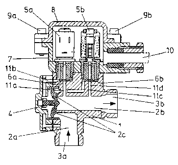
The invention relates to a protection for a fuel valve of a fuel delivery
column, which fuel valve, which can be mounted on said
protection, is built up of a valve housing provided with a bore and a valve
body which is movably accommodated in said bore, wherein the
position of said valve body and thus the fuel supply through said valve can be
adjusted by means of at least one electromagnetic solenoid
to be shielded from the valve, which solenoid extends through said protection
into an opening formed in said valve housing and being in
communication with said bore. The protection according to the invention is
characterized in that it is arranged for several fuel valves and
in that the required electromagnetic solenoids can be shielded by means of one
cover to be mounted on said protection.
L'invention concerne une protection d'une vanne de carburant d'une colonne d'alimentation en carburant, la vanne de carburant, qui peut être montée sur la protection, étant formée d'un logement de vanne doté d'un trou et d'un corps de vanne logé amovible dans ce trou. On peut régler la position du corps de vanne et donc l'alimentation en carburant par cette vanne au moyen d'au moins un solénoïde électromagnétique qui doit être protégé de la vanne, le solénoïde s'étendant à travers la protection dans une ouverture formée dans le logement de vanne pour être en communication avec le trou. La protection selon l'invention se caractérise par le fait qu'elle est destinée à plusieurs vannes de carburant et que les solénoïdes électromagnétiques nécessaires peuvent être protégés par un couvercle à monter sur la protection.
Note: Claims are shown in the official language in which they were submitted.
Note: Descriptions are shown in the official language in which they were submitted.
2024-08-01:As part of the Next Generation Patents (NGP) transition, the Canadian Patents Database (CPD) now contains a more detailed Event History, which replicates the Event Log of our new back-office solution.
Please note that "Inactive:" events refers to events no longer in use in our new back-office solution.
For a clearer understanding of the status of the application/patent presented on this page, the site Disclaimer , as well as the definitions for Patent , Event History , Maintenance Fee and Payment History should be consulted.
| Description | Date |
|---|---|
| Common Representative Appointed | 2019-10-30 |
| Common Representative Appointed | 2019-10-30 |
| Inactive: Expired (new Act pat) | 2019-09-09 |
| Change of Address or Method of Correspondence Request Received | 2018-06-11 |
| Inactive: Late MF processed | 2017-03-22 |
| Letter Sent | 2016-09-09 |
| Inactive: IPC deactivated | 2011-07-29 |
| Inactive: IPC deactivated | 2011-07-29 |
| Inactive: First IPC derived | 2010-02-01 |
| Inactive: IPC from MCD | 2010-02-01 |
| Inactive: IPC from MCD | 2010-02-01 |
| Inactive: IPC expired | 2010-01-01 |
| Inactive: IPC expired | 2010-01-01 |
| Grant by Issuance | 2007-04-24 |
| Inactive: Cover page published | 2007-04-23 |
| Pre-grant | 2007-02-07 |
| Inactive: Final fee received | 2007-02-07 |
| Notice of Allowance is Issued | 2007-01-02 |
| Notice of Allowance is Issued | 2007-01-02 |
| Letter Sent | 2007-01-02 |
| Inactive: Approved for allowance (AFA) | 2006-12-20 |
| Amendment Received - Voluntary Amendment | 2006-10-19 |
| Inactive: S.30(2) Rules - Examiner requisition | 2006-04-27 |
| Inactive: S.29 Rules - Examiner requisition | 2006-04-27 |
| Letter Sent | 2004-08-20 |
| Inactive: Single transfer | 2004-07-13 |
| Letter Sent | 2004-01-05 |
| All Requirements for Examination Determined Compliant | 2003-12-17 |
| Request for Examination Requirements Determined Compliant | 2003-12-17 |
| Request for Examination Received | 2003-12-17 |
| Letter Sent | 2001-08-02 |
| Inactive: Single transfer | 2001-06-22 |
| Inactive: Cover page published | 2001-06-07 |
| Inactive: First IPC assigned | 2001-05-31 |
| Inactive: Courtesy letter - Evidence | 2001-05-29 |
| Inactive: Notice - National entry - No RFE | 2001-05-24 |
| Application Received - PCT | 2001-05-15 |
| Application Published (Open to Public Inspection) | 2000-03-23 |
There is no abandonment history.
The last payment was received on 2006-06-27
Note : If the full payment has not been received on or before the date indicated, a further fee may be required which may be one of the following
Please refer to the CIPO Patent Fees web page to see all current fee amounts.
Note: Records showing the ownership history in alphabetical order.
| Current Owners on Record |
|---|
| TOKHEIM NETHERLANDS B.V. |
| Past Owners on Record |
|---|
| HENRICUS JOHANNES ARNOLDUS WILLEMSEN |
| MARCO VAN SCHAIK |

