Note: Descriptions are shown in the official language in which they were submitted.
CA 02344180 2006-11-22
CATALYTIC GROWTH OF SINGLE-WALL CARBON NANOTUBES
FROM METAL PARTICLES
This invention was made with United States Government support
under United States Grant No. 961240 and Grant No. DMR-9522251 awarded by the
National Aeronautical and Space Administration - Jet Propulsion Laboratory and
the
National Science Foundation, respectively. The United States Government may
have certain rights in the invention.
BACKGROUND OF THE INVENTION
1. Field of the Invention
This invention relates generally to methods of producing single-wall
carbon nanotubes, and to catalysts for use in such methods.
2. Description of Related Art
Fullerenes are closed-cage molecules composed entirely of sp2-
hybridized carbons, arranged in hexagons and pentagons. Fullerenes (e.g., C60)
were first identified as closed spheroidal cages produced by condensation from
vaporized carbon.
Fullerene tubes are produced in carbon deposits on the cathode in
carbon arc methods of producing spheroidal fullerenes from vaporized carbon.
Ebbesen et al. (Ebbesen I), "Large-Scale Synthesis Of Carbon Nanotubes,"
Nature,
Vol. 358, p. 220 (July 16, 1992) and Ebbesen et al., (Ebbesen II), "Carbon
Nanotubes," Annual Review of Materials Science, Vol. 24, p. 235 (1994). Such
tubes are referred to herein as carbon nanotubes. Many of the carbon nanotubes
made by these processes were multi-wall nanotubes, i.e., the carbon nanotubes
resembled concentric cylinders. Carbon nanotubes having multiple walls have
been
described in the prior art. Ebbesen II; Iijima et al., "Helical Microtubules
Of
Graphitic Carbon," Nature, Vol. 354, p. 56 (November 7, 1991).
Another known way to synthesize nanotubes is by catalytic
decomposition of a carbon-containing gas by nanometer-scale metal particles
supported on a substrate. The carbon feedstock molecules decompose on the
particle surface, and the resulting carbon atoms then diffuse through the
particle and
precipitate as part of nanotubes growing from one side of the particle. This
procedure typically produces imperfect multi-walled nanotubes in high yield.
See C.
E. Snyder et al., International Patent Application WO 89/07163 (1989). Its
advantage is that it is relatively simple and can be scaled to produce
nanotubes by the
kilogram.
CA 02344180 2006-11-22
2
Single-wall carbon nanotubes have been made in a DC arc discharge
apparatus of the type used in fullerene production by simultaneously
evaporating
carbon and a small percentage of Group VIII transition metal from the anode of
the
arc discharge apparatus. See lijima et al., "Single-Shell Carbon Nanotubes of
I nm
Diameter," Nature, Vol. 363, p. 603 (1993); Bethune et al., "Cobalt Catalyzed
Growth of Carbon Nanotubes with Single Atomic Layer Walls," Nature, Vol. 63,
p.
605 (1993); Ajayan et al., "Growth Morphologies During Cobalt Catalyzed Single-
Shell Carbon Nanotube Synthesis," Chem. Phys. Lett., Vol. 215, p. 509 (1993);
Zhou et al., "Single-Walled Carbon Nanotubes Growing Radially From YC2
Particles," Appl. Phys. Lett., Vol. 65, p. 1593 (1994); Seraphin et al.,
"Single-
Walled Tubes and Encapsulation of Nanocrystals Into Carbon Clusters,"
Electrochem. Soc., Vol. 142, p. 290 (1995); Saito et al., "Carbon Nanocapsules
Encaging Metals and Carbides," J. Phys. Chem. Solids, Vol. 54, p. 1849 (1993);
Saito et al., "Extrusion of Single-Wall Carbon Nanotubes Via Formation of
Small
Particles Condensed Near an Evaporation Source," Chem. Phys. Lett., Vol. 236,
p.
419 (1995). It is also known that the use of mixtures of such transition
metals can
significantly enhance the yield of single-wall carbon nanotubes in the arc
discharge
apparatus. . See Lambert et al., "Improving Conditions Toward Isolating Single-
Shell
Carbon Nanotubes," Chem. Phys. Lett., Vol. 226, p. 364 (1994). While this arc
discharge process can produce single-wall nanotubes, the yield of nanotubes is
low
and the tubes exhibit significant variations in structure and size between
individual
tubes in the mixture. Individual carbon nanotubes are difficult to separate
from the
other reaction products and purify.
High quality single-wall carbon nanotubes have also been generated
by arc evaporation of a graphite rod doped with Y and Ni. See C. Journet et
al.,
Nature 388 (1997) 756. These
techniques allow production of only gram quantities of single-wall carbon
nanotubes.
An improved method of producing single-wall nanotubes is described
in International Patent Application WO 97/09272, entitled "Ropes of Single-
Wall
Carbon Nanotubes". This method uses, inter alia, laser vaporization of a
graphite
substrate doped with transition metal atoms, preferably
CA 02344180 2006-11-22
3
nickel, cobalt, or a mixture thereof, to produce single-wall carbon nanotubes
in
yields of at least 50% of the condensed carbon. See A. Thess et al. (1996),
Science
273:483. i ne single-wall nanotubes produced by this method tend to be formed
in
clusters, termed "ropes," of 10 to 1000 single-wall carbon nanotubes in
parallel
alignment, held together by van der Waals forces in a closely packed
triangular
lattice. Nanotubes produced by this method vary in structure, although one
structure
tends to predominate. These high quality samples have for the first time
enabled
experimental confirmation of the structurally dependent properties predicted
for
carbon nanotubes. See J. W. G. Wildoer, L C. Venema, A. G. Rinzler, R. E.
Smalley, C Dekker (1998), Nature, 391:59; T. W. Odom, J. L. Huang, P. Kim, C.
M.
Lieber (1998), Nature, 391:62.
Although the laser vaporization process produces improved single-
wall nanotube preparations, the product is still heterogeneous, and the
nanotubes are
too tangled for many potential uses of these materials. In addition, the
vaporization
of carbon is a high-energy process and is inherently costly. Therefore, there
remains
a need for improved methods of producing single-wall nanotubes of greater
purity
and homogeneity. Furthermore, applications could make use of the properties of
single-wall carbon nanotubes if only they were available in a form where they
were
attached directly to the surface of a macroscopic object. However, such
components
have not been produced up to now.
A method of producing carbon fibers from single-wall carbon
nanotubes is described in International Patent Application WO 98/39250. The
single-wall nanotube molecules are produced in substantially two-dimensional
array
made up of single-walled nanotubes aggregating (e.g., by van der Waals forces)
in
substantially parrallel orientation to form a monolayer extending in
directions
substantially perpendicular to the orientation of the individual nanotubes.
Such
monolayer arrays can be formed by conventional techniques employing
"self-assembled monolayers" (SAM) or Langmiur-Blodgett films, see Hirch, pp.
75-76.
Typically, SAMs are created on a substrate which can be a metal
(such as gold, mercury or ITO (indium-tin-oxide)). The molecules of interest,
here
the single-wall nanotube molecules, are linked (usually covalently) to the
substrate
CA 02344180 2001-03-16
WO 00/17102 PCT/US99/21367
4
through a linker moiety such as -S-, -S-(CH2)õ-NH-, -Si03(CHZ)3NH- or the
like.
The linker moiety may be bound first to the substrate layer or first to the
single-wall
nanotube molecule (at an open or closed end) to provide for reactive self-
assembly.
Langmiur-Blodgett films are formed at the interface between two phases, e.g.,
a
hydrocarbon (e.g., benzene or toluene) and water. Orientation in the film is
achieved by employing molecules or linkers that have hydrophilic and
lipophilic
moieties at opposite ends.
The production of single-wall carbon nanotubes by metal-catalyzed
disproportionation of carbon monoxide has been reported. See Dai, et al.
(1996),
Chem. Phys. Lett., 260:471-475. Preformed catalyst particles were made from a
50:50 mixture of Ni/Co supported on fumed alumina nanoparticles using known
methods (See Int. Pat. WO 89/07163 (1989)). The diameter of the single- or
multi-
wall nanotube structure growing from a catalyst particle is related to the
dimensions
of the catalyst particle itself. Using the known methods of catalyst particle
preparation, it is not possible to provide nanoparticles with a uniform
optimum size
to produce only single-wall nanotubes, and the growth process of Dai, et al.,
does
not provide high yields of single-wall nanotubes because the larger particles
produce
multiwall nanotubes.
SUMMARY OF THE INVENTION
This invention provides a method for predominant production of
single-wall carbon nanotubes comprising: providing a supported transition
metal
catalyst supported on an inert surface contacted with a suitable feedstock gas
(e.g.
CO, or any of the known effective hydrocarbon gasses) at a temperature and
pressure at which single-wall carbon nanotube growth occurs. Enhanced rates of
production for single-wall nanotubes are provided by first placing catalyst
material
on an appropriate supporting substrate and treating the catalyst material so
that it
produces predominantly single-wall carbon nanotubes. At least initially, the
conditions ensure that the reaction to form nanotubes is limited by the supply
of
carbon to the catalytic site, rather than by the rate of diffusion of carbon
through the
catalytic particle. This may be achieved via a chemical process in which the
carbon
contained in a controlled amount of feedstock gas interacts with catalyst
particles.
Under the appropriate conditions carbon in the feedstock gas is formed into
single-
CA 02344180 2001-03-16
WO 00/17102 PCT/US99/21367
wall nanotubes on the catalyst particles of less than 2-nanometer diameter but
is
formed into graphitic layers that encapsulate the larger catalyst particles,
deactivating them as catalysts. Catalyst particles of greater than about 2
nanometers
in diameter are more likely to form multiwall nanotubes, and since they are
rendered
5 ineffective by the process, the only remaining active catalyst particles
support
growth of primarily single-wall nanotubes. In a preferred embodiment, the
method
of this invention provides for treatment of supported catalyst material to
deactivate
catalyst particles that do not support growth of the desired nanotube types,
with
subsequent change of the feedstock composition or density to accelerate growth
of
the desired form of single-wall nanotubes. The method of this invention is
capable
of producing material that is >50 % SWNT, more typically >90 % SWNT, or even
>99 % SWNT.
This invention also provides a catalyst/support system structured so
that access of the feedstock gas to the catalyst is enhanced by that
structure.
Preferably, the catalyst is deposited so that there is clear distance between
catalyst
locations by dispersion of small catalyst particles on the substrate surface
or other
methods of deposition known to those skilled in the art.
The production of high quality single-wall carbon nanotubes, in some
cases including double-wall carbon nanotubes, in yields much larger than
previously
achieved by catalytic decomposition of carbon-containing precursor gases is
disclosed. The nanotubes formed are connected to and grow away from the
catalyst
particles affixed to the catalyst support surface. If the growth time is
short, the tubes
can be only a fraction of one micron long, but if the growth time is
prolonged,
single-wall carbon nanotubes in this invention can grow continuously to
arbitrary
lengths. The present invention demonstrates a means for nucleating and growing
nanotubes only from the smallest of the supported catalyst particles, which
produce
single-wall carbon nanotubes, while deactivating the larger particles so that
no
multi-walled nanotubes are produced. This allows the growth exclusively of
single-
wall carbon nanotubes from catalyst systems previously thought to produce only
larger diameter multi-walled nanotubes.
According to one embodiment of the present invention, a process for
producing single wall carbon nanotubes is disclosed. The process comprises the
CA 02344180 2001-03-16
WO 00/17102 PCT/US99/21367
6
steps of: (1) providing a supported nanoscale particulate transition metal
catalyst in a
reaction zone; (2) supplying a gaseous carbon-containing compound to the
reaction
zone under conditions, at least initially, so that the compound inactivates
catalyst
particles that have a diameter large enough to catalyze the production of
multi-wall
carbon nanotubes; and (3) contacting the catalyst particles that have a
diameter small
enough to catalyze the production of primarily single-wall carbon nanotube
which
remain active under the conditions with the gaseous carbon-containing
compound.
The gaseous carbon-containing compound may be a hydrocarbon. In this case, the
gaseous hydrocarbon may be supplied to the reaction zone at a rate that is low
enough to cause the inactivation of larger diameter catalyst particles while
causing
the growth of single wall nanotubes from the smaller diameter catalyst
particles.
Under such conditions, it is believed the larger diameter catalyst particles
are
inactivated by encapsulation by graphitic layers before any multi-wall carbon
nanotubes can grow therefrom. The gaseous carbon-containing compound may also
be CO. In this case, the CO is contacted with the supported catalyst at a
temperature
and pressure that inactivates large diameter catalyst particles but produces
single-
wall carbon nanotubes in high yield. In either case, the conditions in the
reaction
zone may be changed, after the inactivation of the larger diameter catalyst
particles,
to conditions that favor the production of single-wall carbon nanotubes.
The catalyst may include nanoscale transition metal atom clusters
supported on a substantially planar support. The transition metal atom
clusters may
be substantially uniformly disposed on the planar surface in close proximities
to one
another so that individual single-wall carbon nanotubes, or that bundles or
ropes of
generally aligned single-wall carbon nanotubes, grow from the supported
catalyst
particles. Changing the temperature in the reaction zone may selectively
change the
yield of single-wall carbon nanotubes.
BRIEF DESCRIPTION OF THE DRAWINGS
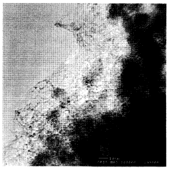
Fig. I is an image of an Individual single-wall nanotubes grown by
reacting 1200 sccm CO at 850 C over an alumina supported Mo particle system.
Fig. 2 is a graph of nanotube yield as a function of time for CO over
Mo particles and C2H4 over Fe:Mo particles. The fits give time dependencies of
t0-5
and t0.4 respectively.
CA 02344180 2001-03-16
WO 00/17102 PCT/US99/21367
7
Fig. 3 is a TEM image of single-wall carbon nanotube grown at
850 C by 1200 sccm CO over an alumina:Fe:Mo catalyst.
Fig. 4 is a SEM image of nanotube ropes grown at 800 C in 1000
sccm Ar, 0.66 sccm C2H4, 0.33 sccm H2.
Fig. 5 is a TEM of the same material that shows ropes that consist of
nanotubes of diameter 0.5nm - 3 nm and 1 or 2 walls, respectively.
Fig. 6 is a graph of the energies of capsules and single wall nanotubes
relative to an infinite graphene sheet.
DETAILED DESCRIPTION OF THE EMBODIMENTS
Carbon has, from its very essence, not only the propensity to self-
assemble from a high temperature vapor to form perfect spheroidal closed cages
(of
which C60 is prototypical), but also (with the aid of a transition metal
catalyst) to
assemble into perfect single-wall cylindrical tubes. These tubes, which may be
thought of as one-dimensional single crystals of carbon, are true fullerene
molecules.
Single-wall carbon nanotubes are much more likely to be free of
defects than multi-wall carbon nanotubes. Defects in single-wall carbon
nanotubes
are less likely than defects in multi-walled carbon nanotubes because the
latter have
neighboring walls that provide for easily-formed defect sites via bridges
between
unsaturated carbon valances in adjacent tube walls. Since single-wall carbon
nanotubes have fewer defects, they are stronger, more conductive, and
therefore
more useful than multi-wall carbon nanotubes of similar diameter.
Carbon nanotubes may have diameters ranging from about 0.6
nanometers (nm) for a single-wall carbon nanotube up to 3nm, 5nm, 10nm, 30nm,
60nm or l00nm for single-wall or multi-wall carbon nanotubes. The carbon
nanotubes may range in length from 5nm up to 1 millimeter (mm), 1 centimeter
(cm), 3cm, 5cm, or greater. The process described here enables one to produce
high
quality single-wall carbon nanotubes, and, in some cases double-wall carbon
nanotubes, in yields much larger than previously achieved in growth from
supported
catalysts. The yield of single-wall carbon nanotubes in the product made by
this
invention is unusually high. Yields of single-wall carbon nanotubes greater
than
90% are possible with this invention. This is achieved by nucleating and
growing
nanotubes from the smallest of the supported catalyst particles, which produce
CA 02344180 2001-03-16
WO 00/17102 PCT/US99/21367
8
single-wall carbon nanotubes, and deactivating the larger particles so that
few multi-
walled nanotubes are produced.
Catalyst Support
This invention deals with development of supported catalyst systems
that provide an effective means for production of single-wall nanotubes.
Single-
walled carbon nanotubes have been synthesized by the catalytic decomposition
of
both carbon monoxide and ethylene over a supported metal catalyst known to
produce larger multi-walled nanotubes. Under certain conditions, there is no
termination of nanotube growth, and production appears to be limited only by
the
diffusion of reactant gas through the product nanotube mat that covers the
catalyst.
Catalyst geometry may be selected to overcome the diffusion limitation.
Catalyst geometry which may be selected to overcome the negative
effects due to restricted gas phase diffusion includes distribution or
deposition of
catalyst material in specific, separated regions on a supporting structure.
Such
catalyst geometries will penmit growth of nanotubes in specific isolated
locations,
allowing good access of the feedstock to the catalyst. Structuring the support
substrate itself in a way that feedstock permeates the substrate before
reaching the
catalyst particles, further enhances access of the feedstock to the substrate.
Such
supported catalysts promote bulk catalytic production of single-wall
nanotubes. The
catalyst-substrate systems of this invention further promote the growth of
nanotubes
that are predominantly single-walled tubes in a specific size range, rather
than the
large irregular-sized multi-walled carbon fibrils that are known to grow from
supported catalysts. Catalyst geometry which overcomes the diffusion
limitation
allows bulk catalytic production of single-wall carbon nanotubes by supported
metal
catalysts.
The nanoscale particulate transition metal catalyst according to the
present invention may be provided on a chemically compatible, refractory
nanoseale
support particle. The support material must remain solid under reaction
conditions,
must not poison the catalyst, and must be easily separated from the product
after
formation. Alumina, carbon, quartz, silicates, and aluminum silicates, such as
mullite, are all suitable materials for the support. The support may take the
form of
spheres, irregularly shaped particles, flakes and the like. Preferred are
supports that
CA 02344180 2001-03-16
WO 00/17102 PCT/US99/21367
9
provide substantially planar surfaces, e.g., flakes. The support may range in
size
from about 10 nm to centimeters.
Transition Metal Catalyst
A variety of transition metal-containing clusters are suitable as
catalysts when used with an appropriate combination of reaction parameters.
The
transition metal catalyst can be any transition metal that will cause
conversion of the
carbon-containing feedstock described below into highly mobile carbon radicals
that
can rearrange at the growing edge to the favored hexagon structure. Suitable
materials include transition metals, and particularly the Group VIB chromium
(Cr),
molybdenum (Mo), tungsten (W) or Group VIIIB transition metals, e.g., iron
(Fe),
cobalt (Co), nickel (Ni), ruthenium (Ru), rhodium (Rh), palladium (Pd), osmium
(Os), iridium (Ir) and platinum (Pt) or mixtures thereof. Metals from the
lanthanide
and actinide series may also be used. Preferred are Fe, Ni, Co and mixtures
thereof,
such as a 50/50 mixture (by weight) of Ni and Co or a mixture of Fe/Ni. Any of
these transition metals individually or in combination with any of the other
transition
metals listed may be used in clusters to serve as a catalyst for single-walled
carbon
nanotube growth. Particularly preferred catalysts are mixtures of two or more
of the
listed metals.
The transition metal clusters may have a size from about 0.5 nm to
over 30 nm. Clusters in the range of 0.5 to 3 nm will produce single-wall
nanotubes,
while larger clusters tend to produce multiwall nanotubes with outer diameters
greater than about 3 nm. In a preferred mode, the larger clusters are
inactivated by
the process of this invention, with the result that catalytic production of
nanotubes
using this preferred catalyst will be predominately single-wall nanotubes. The
transition metal clusters may be substantially uniformly dispersed on the
support
surface in close proximity to one another so that the single-wall nanotubes
that grow
from the support form bundles or ropes of generally aligned single-wall carbon
nanotubes. Alternatively, transition metal clusters may be dispersed on the
support
surface so that there is clear separation between the clusters, so that the
single-wall
nanotubes that grow from the support are separate from one another.
Catalysts may be prepared using known methods, and can be (i)
prepared in advance in fully active form, (ii) prepared in precursor form
followed by
CA 02344180 2006-11-22
an activation step (e.g., treating in an appropriate atmosphere), or (iii)
fonned in situ
in the reaction zone. The catalyst precursors may be those that convert to
active
form under growth conditions such as oxides, other salts or iigand stabilized
metal
complexes. As an example, transition metal complexes with alkylamines
(primary,
5 secondary or tertiary) can be employed. Similar alkylamine complexes of
transition
metal oxides also can be employed. In situ formation, as described below, is
preferred.
One suitable catalyst preparation method is disclosed in U.S. Patent
No. 5,707,916, (1998), by C. E. Snyder et al.
10 According to this method, fumed alumina (Degussa) is stirred with
methanol, and to the resulting slurry is added a methanol solution of metal
salts
(ferric nitrate and/or bis(acetylacetonato)-dioxomolybdenum (VI). The combined
slurry is stirred for several hours, dried in a rotary evaporator, baked in
vacuum at
180 C for 12-15 hours, and ground into a fine powder.
Carbon Source
Suitable carbon-containing compounds include carbon monoxide and
hydrocarbons, including aromatic hydrocarbons, e.g., benzene, toluene, xylene,
cumene, ethylbenzene, naphthalene, phenanthrene, anthracene or mixtures
thereof,
non-aromic hydrocarbons, e.g., methane, ethane, propane, ethylene, propylene,
acetylene or mixtures thereof; and oxygen-containing hydrocarbons, e.g.,
formaldehyde, acetaldehyde, acetone, methanol, ethanol or mixtures thereof. In
a
preferred embodiment, the carbon-containing compound is carbon monoxide (CO)
or ethylene (C2H4).
Conditions Favoring Single-Wall Nanotubes
The reaction step(s) of the present invention that result in the
preferential formation of single-wall nanotubes involves contacting the
supported
metal catalysts with a suitable supply of gaseous carbon-containing compound,
initially under conditions that inactivate larger diameter catalyst.
Typically, such
conditions will force the rate of the catalytic process to be limited by the
supply of
carbon to the catalyst cluster itseIf rather than a process that is limited by
the rate of
diffusion of carbon through the catalyst to the precise location at which
carbon
atoms are bonding to one another. This can be achieved by lowering the carbon
CA 02344180 2001-03-16
WO 00/17102 PCT/US99/21367
11
supply to the catalyst, which reduces the carbon concentration in the catalyst
particles. A lower carbon concentration will allow the carbon structures to
form
more slowly, giving each carbon atom more time to anneal to its lowest
energetic
configuration. The lowest-energy bonded carbon structure on a catalyst
particle at
least 3 mn in diameter is an encapsulation of the catalyst particle with a
graphite-like
sheet, while for smaller diameter catalyst particles, the lowest-energy
structure is a
single-walled nanotube growing the particle.
Lower supply of carbon to the catalyst may be achieved in various
ways, depending on the source of gaseous carbon. In the reaction of CO to
produce
nanotubes, slow carbon supply rate arises because CO decomposition is a
bimolecular disproportionation that involves the breaking of two strong CO
triple
bonds: such a reaction is expected to proceed very slowly except at very high
temperatures and pressures much greater than reaction pressure of about 1
atmosphere. The catalytic decomposition of C2H4 proceeds quickly at about I
atm.;
however, the reaction can be slowed down by limiting the partial pressure of
C2H4 to
0.5 Torr.
Reducing the amount of carbon supplied to the catalytic particle may
be accomplished by lowering the gas pressure in the reactor, typically by
reducing
the feed rate into the reactor. Alternatively, the amount of feedstock added
to the
gas flow may be reduced to reduce the partial pressure of the feedstock gas in
the
reactor. Generally, the pressure in the reaction zone should be selected, at
least
initially, to inactive the larger diameter catalyst particles, while favoring
the growth
of single-wall nanotubes from the smaller diameter catalyst particles. As
described
above, the partial pressure at which the carbon supply to the catalytic
particles is rate
limiting will depend on the reaction mechanism. For example, the partial
pressure
for CO that meets this condition will be much higher than the partial pressure
for
ethylene. The initial CO pressure may be from about 0.1 Torr to 10
Atmospheres.
Preferably, the initial pressure in the reaction zone is 1.2 Atmospheres.
Evidence that there has been a successful change of the rate-limiting
step from carbon diffusion through the catalytic particle to carbon supply to
the
catalytic particle can be found in three aspects of the catalytic system of
this
invention. First, the product mass increase rate varies linearly with the
hydrocarbon
CA 02344180 2001-03-16
WO 00/17102 PCT/US99/21367
12
feedstock partial pressure. Second, ignoring termination, the mass growth rate
is
independent of the reaction temperature from 700 C to 850 C. If the reaction
were
limited by diffusion of carbon through the metal, the rate would double from
700 C
to 850 C, assuming an Arrhenius temperature dependence and the activation
energy
of carbon diffusion through iron. Admittedly, the current experiments only
measure
a bulk growth rate as opposed to the microscopic growth rate of an individual
nanotube. However, assuming that the same number of nanotubes nucleate per
unit
mass of catalyst, the two rates are proportional. Finally, the bulk growth
rate of
carbon on the catalyst equals 5% of the mass of carbon in ethylene that flows
over
the catalyst. Although this is not 100% as would be expected of a supply
limited
reaction, a simple model assuming laminar flow suggests that only 5% of the
ethylene molecules strike the catalyst bed. As will be apparent to the skilled
artisan,
the carbon feedstock may be recycled through the catalytic reactor to increase
utilization of the carbon feedstock. Observing any one of these
characteristics, or
even all three, for any feedstock will permit the skilled artisan to adjust
reaction
conditions so that the reaction is limited by the supply of carbon to the
catalyst, not
the diffusion of carbon through the catalytic particle.
The initial temperature in the reaction vessel may be from about
700 C to about 1200 C. Preferably, the temperature in the reaction zone is
initially
850 C.
After selective inactivation of the larger catalyst particles, the process
for forming substantially single-wall nanotubes may either continue with
growth of
SWNT under the same conditions, or reaction conditions may be changed to
enhance production of SWNT by the selective catalyst. In the first step, the
reaction
zone may be supplied with a precursor under conditions, at least initially,
that
inactivate catalyst particles that have a diameter large enough to catalyze
the
production of multi-wall carbon nanotubes. These conditions include exposure
of
the catalyst particles to CO gas at 1.2 atmospheres. Further, the precursor
may be
supplied to the reaction zone at a rate that is low enough to cause the
inactivation of
larger diameter catalyst particles, e.g., particles larger than 3 nm. A
typical low flow
rate for the precursor may be from about 500 to about 200 sccm in a 1-inch
diameter
CA 02344180 2001-03-16
WO 00/17102 PCT/US99/21367
13
tube furnace. A preferred CO flow rate is about 1200 sccm in a one-inch
diameter
tube furnace.
Once the larger diameter catalyst particles have been deactivated, the
conditions in the reaction zone may be changed to conditions that enhance the
production of single-wall carbon nanotubes. This includes increasing the
temperature and/or the pressure of CO or changing to another of the carbon-
bearing
reagent gases mentioned above.
In an alternate embodiment, the conditions in the reaction zone may
be selected such that there is no need to change reaction zone conditions to
favor the
growth of single-wall nanotubes from the smaller diameter catalyst particles
after
inactivating larger diameter catalyst particles. Conditions initially selected
also
allow the single-wall nanotubes to remain active under these conditions. For
example, the CO pressure in the reaction zone may be from about 500 Torr to
about
2000 Torr. The temperature may be from about 600 C to about 900 C. The flow
rate of the precursor may be from about 500 to about 2000 sccm in a 1-inch
diameter
tube furnace.
The yield of single-wall carbon nanotubes may selectively changed
by changing the temperature in the reaction zone. The mass yield of SWNT is
temperature dependent, with the yield increasing with increasing temperature.
Selectivity can also be affected by temperature, with the product mix varying
from
30% double wall nanotubes at 700 C to 70% double wall nanotubes at 850 C.
As shown in Figures 1 and 4, both CO disproportionation over Mo
catalyst particles at 850 C and the reaction of C2H4 with Fe/Mo particles at
700 C
appear to generate single-wall carbon nanotubes that grow continuously without
termination of the growth reaction. These results constitute the first
demonstration
of continuous generation of single-wall carbon nanotubes with lengths that
are, in
principle, arbitrarily long. In practice, however, the mass of the grown
nanotubes
exhibits a time dependence that is less than linear, so that growth slows more
and
more with increasing time (a fit of the data sets in Fig. 2 give roughly
square root
dependencies of yield on time). This slowing growth may be due to the
increasing
diffusion time of the carbon feedstock molecules through the thickening mat of
nanotubes surrounding the catalyst particles.
CA 02344180 2001-03-16
WO 00/17102 PCT/US99/21367
14
Without intending to be bound by a particular mechanism, the
inventors believe that the basis for the present invention is that the
energetics of
structures that could grow off of the catalyst particles by calculating the
energy per
carbon atom as a function of structure size are considered. For single-wall
carbon
nanotubes, the caps were neglected in favor of the vastly greater number of
carbon
atoms in the side walls. The energies of carbon atoms at the nanotube-metal
interface and nanotube ends were neglected since only the final product
energies, not
nucleation or growth mechanisms, are considered. A graphene capsule entirely
surrounding the catalyst particle was also considered. For all catalyst
particle
diameters, one expects the graphene cylinder to be lower in energy than the
capsule
since the cylinder has only simple curvature compared with the complex
curvature
of the capsule. However, the attractive interaction between the graphene
capsule
and the metal particle will lower the energy per atom of the capsule. Simple
formulas for the energies of curved graphene sheets for the nanotubes and
large
fullerenes for the capsules were used. An estimate for the graphene-metal
interaction was taken from an experimental measurement of the energy of the
graphite ferrite interface. The result, displayed in Fig. 6, shows that the
nanotube
energy is lower than that of the capsule in a diameter range similar to the
single-wall
carbon nanotube diameters. These calculations lend support to the hypothesis
that
supply-limited growth allows more time to anneal to the lowest energy
structure so
that smaller particles produce nanotubes while larger particles are
encapsulated.
This model could give further insight into the presence or absence of double-
wall
carbon nanotubes and multi-walled nanotubes if the relative graphene-graphene
and
graphene-metal interaction strengths were well-known.
For experiments in which the reaction time is short, it has been
observed that the single-wall carbon nanotubes grow with a particle at one end
and
closed at the other. This supports nucleation of these nanotubes by the
yarmulke
mechanism in which a hemispherical graphene cap forms on the catalyst
particles
and lifts off to nucleate closed nanotubes.
Product
SWNT produced by the method of this invention are substantially
free of amorphous or pyrolytic carbon (i.e., none is observed in TEM of the
CA 02344180 2001-03-16
WO 00/17102 PCT/US99/21367
nanotubes) unless the process is carried out with excess hydrocarbon
feedstock. The
product of a typical process for making mixtures containing single-wall carbon
nanotubes is a tangled felt, which can include deposits of amorphous carbon,
graphite, metal compounds (e.g., oxides), spherical fullerenes, catalyst
particles
5 (often coated with carbon or fullerenes) and possibly multi-wall carbon
nanotubes.
The single-wall carbon nanotubes may be aggregated in "ropes" or bundles of
essentially parallel nanotubes.
Nanotubes prepared using the catalytic method of this invention tend
to be less contaminated with pyrolytic or amorphous carbon than nanotubes
prepared
10 by prior art methods. Furthermore, by using a catalyst with a narrow size
distribution, the nanotubes produced consequently have a narrow size
distribution.
This will minimize the need for post-production activities to clean up the
nanotube
preparation. To the extent that the nanotube product contains pyrolytic carbon
which needs to be removed, various procedures are available to the skilled
artisan
15 for cleaning up the product. Suitable processes for purifying carbon
nanotubes
prepared according to this invention include the processes described in
International
Patent Publication WO 98/39250.
According to the invention, predominantly single-wall carbon
nanotubes, with a portion of double-wall carbon nanotubes under some
conditions,
are produced with diameters in the range from about 0.5 to about 3 nm.
Typically,
no 5 to 20 nm diameter multi-walled nanotubes are produced by supported
catalyst
particles. The key difference responsible for these effects is that the growth
reaction
rate is limited by the supply of carbon to the catalyst particles, whereas the
multi-
walled nanotube growth is thought to be limited by the diffusion of carbon
through
the catalyst particles.
The single-wall nanotubes of the present invention may have lengths
exceeding one micron. The length may be controlled by lengthening or
shortening
the amount of time the catalyst is exposed to the feedstock gas at an
appropriate
temperature and pressure. In one embodiment, under proper conditions the
single-
wall nanotubes can grow continuously to an arbitrary length.
Single-wall nanotubes formed in the present invention are observed
to form into organized bundles or "ropes" as they grow from catalyst particles
in
CA 02344180 2006-11-22
16
close proximity to each other. Examples of this behavior are shown in Figs. 4
& 5.
Such ropes of SWNT may be removed from the supported catalyst for subsequent
processing and/or utilization, or they may be used "as is" while still
attached to the
catalyst particle. SWNT prepared according to this invention using a supported
catalyst with widely dispersed catalytic particles may be recovered prior to
aggregation of the individual nanotubes. These nanotubes may be collected in
the
form of a mat or felt with random orientation in two dimensions or
individually for
particular uses.
Using the product nanotubes
Carbon nanotubes, and in particular the single-wall carbon nanotubes
of this invention, are useful for making electrical connectors in micro
devices such
as integrated circuits or in semiconductor chips used in computers because of
the
electrical conductivity and small size of the carbon nanotube. This invention
provides a means of establishing a carbon nanotube directly in contact with a
surface, but extending away from that surface. This occurs naturally in the
present
invention as the tube is grown from a catalyst particle in contact with the
surface of
a larger object (the catalyst support). This invention's provision of a simple
means
for creating structures that comprise a support surface with one or more
nanotubes
attached and extending away from that surface is particularly useful in known
applications of nanotubes as probes in scanning tunneling microscopes (STM)
and
atomic force microscopes (AFM) and as field emitters of electrons for
electronic
applications. The carbon nanotubes are useful as antennas at optical
frequencies,
and as probes for scanning probe microscopy such as are used in scanning
tunneling
microscopes (STM) and atomic force microscopes (AFM). The carbon nanotubes
are also useful as supports for catalysts used in industrial and chemical
processes
such as hydrogenation, reforming and cracking catalysts. The nanotubes may be
used, singularly or in multiples, in power transmission cables, in solar
cells, in
batteries, as antennas, as molecular electronics, as probes and manipulators,
and in
composites.
EXAMPLE
CA 02344180 2001-03-16
WO 00/17102 PCT/US99/21367
17
In order to facilitate a more complete understanding of the invention,
an Example is provided below. However, the scope of the invention is not
limited to
specific embodiments disclosed in this Example, which is for purposes of
illustration
only.
1. Preparation
Single wall carbon nanotubes may be grown by passing carbon-
containing gases (CO or C2H4) at elevated temperatures over nanometer-size
metal
particles supported on larger (10-20 nm) alumina particles. Two different
metal
catalysts may be used, one containing pure Mo, the other containing Fe and Mo.
The ratio of FE to Mo may be 9:1. Both catalysts were made using a method
known in the art.
For each growth experiment, a quartz boat containing a carefully
weighed amount (typically 20 mg) of the catalyst powder was placed in the
center of
a 1 inch quartz tube furnace. The system was purged with Ar, then heated under
flowing reactant gases to an elevated temperature for a controlled time. The
resulting catalyst material, which now also contains reaction products
dominated by
single-wall carbon nanotubes, was removed from the boat and weighed again. The
yield is defined as the mass increase divided by the original catalyst mass.
Samples
were prepared for TEM imaging by sonicating this material in methanol and drop-
drying the resulting suspension onto TEM grids.
2. Production of single-wall carbon nanotubes
The production of single-wall carbon nanotubes by the
disproportionation of CO over alumina-supported Mo particles is greatly
improved.
The catalyst is 34:1 alumina:Mo by mass. The reaction is carried out at 850 C
under
a flow of 1200 sccm of CO at 900 Torr. The resulting material, which consists
of
single-wall carbon nanotube very monodisperse in diameter (0.8 to 0.9 nm), is
shown in Fig. 1. Particles of the fumed alumina support, 10 to 20 nm in size,
are also
visible in this and subsequent TEM images. The yield of nanotubes is plotted
as a
function of reaction time in Fig. 2. The yield continues to increase even for
very
long reaction times.
CO also forms nanotubes with a second catalyst. The second catalyst
is prepared with 90:9:1 alumina:Fe:Mo by mass. The reaction, when carried out
CA 02344180 2001-03-16
WO 00/17102 PCT/US99/21367
18
exactly as described above for the alumina:Mo catalyst, yields nanotubes of a
wider
diameter distribution, 0.5 to 3 nm, with single-wall carbon nanotubes and some
double-wall carbon nanotubes. A representative TEM image is shown in Fig. 3.
For
this catalyst, the yield increases with time initially, but is limited to
about 40% after
one hour of exposure. No additional mass increase is observed even for much
longer
exposures (up to 20 hours).
Single-wall carbon nanotubes from C2H4 have been grown using this
technique. The 90:9:1 alumina:Fe:Mo catalyst is first reduced by exposing the
catalyst to 1000 sccm Ar and 0.33 sccm H2 at 800 C for 30 minutes. The growth
reaction then proceeds at the reaction temperature by adding 0.66 sccm C2H4 to
the
gas flow. The resulting product is nanotube bundles containing single-wall
carbon
nanotubes and double-wall carbon nanotubes, shown in Figures 4 and 5. One
hundred nanotube cross sections were observed at several reaction temperatures
to
count the relative number of single- to double-walled nanotubes. The amount of
double-wall carbon nanotubes increases from 30% at 700 C to 70% at 850 C.
Outer
diameters of the individual tubes in a bundle range from 0.5 to 3 nm. There
appears
to be no correlation between outer diameter and number of walls, other than
that the
smallest nanotubes (< I nm diameter) are never double-walled.
The mass yield of nanotubes increases at a similar rate for reaction
temperatures from 700 C to 850 C, but the termination is temperature
dependent.
For reactions at 850 C, the yield increases until it reaches 7%, at which
point the
growth terminates. As the reaction temperature is lowered, the yield reaches
higher
levels before growth termination. At 700 C, the growth does not terminate, but
its
rate decreases as shown in Fig. 2.
The present invention demonstrates the ability to grow nanotubes by
catalytic decomposition of C2H4 and CO only from the small particles in a
supported catalyst system, leading to the growth of single-wall carbon
nanotubes
and deactivation of multi-walled nanotube growth by encapsulation of larger
particles. For certain conditions, nanotubes can be grown to arbitrary length,
but
become limited by the diffusion of reactants to the catalyst particles. This
problem
has been solved for the production of multi-walled nanotubes from this
catalyst by
using flat alumina flakes, as opposed to fumed alumina particles, so that the
CA 02344180 2001-03-16
WO 00/17102 PCT/US99/21367
19
nanotubes grow aligned in large bundles, keeping their growing ends exposed to
the
gaseous feedstock. Similar modifications to the current technique may allow
the
bulk production of single-wall carbon nanotubes.
While the invention has been described in connection with preferred
embodiments, it will be understood by those skilled in the art that other
variations
and modifications of the preferred embodiments described above may be made
without departing from the scope of the invention. Other embodiments will be
apparent to those skilled in the art from a consideration of the specification
or
practice of the invention disclosed herein. It is intended that the
specification is
considered as exemplary only, with the true scope and spirit of the invention
being
indicated by the following claims.